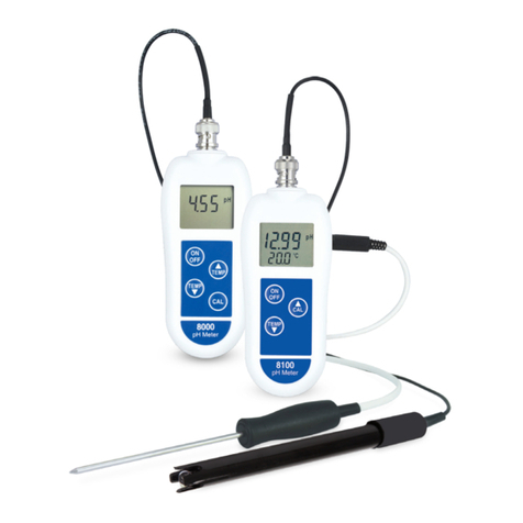
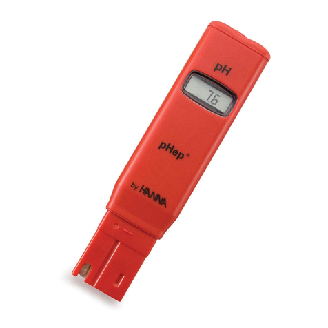
Bayrol pH FUN User manual

Instructions pH FUN V1
Page 1 of 28
Instruction manual
pH FUN

Instructions pH FUN V1
Page 2 of 28
Table of contents
1INSTALLING THE PH FUN..............................................................................................5
1.1 General notes on installation: .................................................................................... 5
1.2 Selecting the installation location.............................................................................. 5
1.3 Mounting the pH FUN on the wall .............................................................................. 5
1.4 Installing the measurementwater circuit.................................................................. 6
1.5 Electrical connection................................................................................................... 6
1.5.1 Connections on the controller housing........................................................................... 6
1.5.2 Earthing ofthe pH value measurement.......................................................................... 7
1.6 Connecting the dosing line for pH-Minus ................................................................. 7
1.7 Dosing of pH-Plus (increase ofthe pH value)........................................................... 7
1.8 Installation plans.......................................................................................................... 8
1.8.1 Connection pH FUN for pH-Minus .................................................................................8
1.8.2 Connection pH FUN for pH-Plus....................................................................................8
2PUTTING INTO OPERATION.......................................................................................... 9
3MAINTAINING THE PH FUN ......................................................................................... 10
3.1 Maintenance plan....................................................................................................... 10
3.1.1 Checking the hoses...................................................................................................... 10
3.1.2 Cleaning the filter ......................................................................................................... 10
3.1.3 Dosing pump hoses ..................................................................................................... 10
3.1.4 Replacing hoses........................................................................................................... 11
3.2 Electrode information................................................................................................ 11
3.2.1 Electrode wear ............................................................................................................. 11
3.2.2 Electrode care.............................................................................................................. 12
3.2.3 pH7 Calibration ofthe electrode................................................................................... 12
3.3 Decommissioning / Winter storage of the system ................................................. 12
4OPERATING THEPH FUN............................................................................................ 13
4.1 Display and operating field ofthe pH FUN.............................................................. 13
4.1.1 Button functionsin the normal view.............................................................................. 14
4.1.2 Performing a parameter setting.................................................................................... 14
4.2 The pH FUN menu...................................................................................................... 14
4.3 Setting options of the pH FUN.................................................................................. 16
4.3.1 Menu navigation........................................................................................................... 16
4.3.2 Switching the operating mode...................................................................................... 16
4.3.3 Setting optionsin the menu.......................................................................................... 16
4.4 Initial operation of the pH FUN ................................................................................. 18
4.5 The energy-saving mode of the pH FUN ................................................................. 18
5PERFORMING AMANUAL DOSING ............................................................................ 19
5.1 Calculating the manual dosing................................................................................. 19
5.2 Safetyfunctions for a manual dosing...................................................................... 19
6PERFORMING THE PH7 CALIBRATION ..................................................................... 20
7MEASUREMENTAND CONTROL OF THEPH VALUE............................................... 21
7.1 Dosing rate and dosing cycle................................................................................... 21
7.2 Calculating the dosing rate.......................................................................................21
8ALARMS AND SAFETY FUNCTIONS........................................................................... 22
8.1 The alarm viewof the pH FUN.................................................................................. 22
8.2 Acknowledging alarms.............................................................................................. 22
8.3 Blocking dosing......................................................................................................... 22
8.4 Possible displays in the alarm view......................................................................... 22
9POSSIBLE PROBLEMSAND THEIR REMEDY ........................................................... 24
9.1 The pH FUN reports an alarm...................................................................................24
9.2 The pH FUN does notdisplaythe correct pH value ............................................... 25
9.3 The pH value in the pool is not correct ................................................................... 25
9.4 The dosing pump is not running.............................................................................. 25
9.5 The pH7 calibration does not work.......................................................................... 26
9.6 The displayofthe pH FUN is dark............................................................................ 26
10 SERVICE........................................................................................................................ 27
10.1 Connections in the controller housing.................................................................... 27
10.2 Replacing the fuses................................................................................................... 27

Instructions pH FUN V1
Page 3 of 28
Symbols
General dangerwarning
Information about dangerdue to electrical voltage
Important information
General Information
General danger warning:
The dosing fluidsused are corrosive and or inflammable. Neverallowthe two endsofthe
pressure hoseson vacuumpumps to hang loose, as thiswill permit the corrosive and
inflammable fluidsto escape.
Important:
During installation and operation, alwaysobserve the relevant health and safetyregulationswhen
installing and using the device. It must onlybe installed and operated byqualified expert
personnel.
General danger warning:
Changing the systemsettings (default values) can be dangerousto persons under certain
circumstances. Therefore, changesmust onlybe made bytrained technicians.
The operator assumesliabilityifthe equipment isused improperlyor the settings are modified
incorrectly!
General danger warning:
The systemmust be switched offimmediatelyand protected against being switched on again if it
is probable that the systemcannot be operated safelyand without danger.
This is the case, for example, if
•the systemis visiblydamaged,
•the systemno longer appears to be functional forwhatever reason,
•the systemwas stored forlengthyperiodsunderunfavourable conditions(e.g. improper winter
storage)

Instructions pH FUN V1
Page 4 of 28
Congratulationson the purchase ofyour pH FUN measuring, controlling and dosing system. You have selected a
device that ensures a high operational safetywith its high-qualitydesign and sophisticated construction.
The pH FUN ensures the adherence to the most important water treatment parameter, the pH value. Thus, you only
need to lookafter the disinfection.
The use ofBAYROL algaecide and flocculant products is additionallyrecommended. The product programis perfectly
matched to guarantee a perfect waterqualitywith verylittle effort. Your swimming pool dealerwill gladlyadvise you.
Please observe that the proper functioning of the device can onlybe ensured with the use ofBAYROL water treatment
products.
Please read these instructionscarefullyto familiarise yourselfwith the systemand howto operate it.
Ifyou have anyquestions, please contact your dealer or the BAYROL Service Centre.

Instructions pH FUN V1
Page 5 of 28
1 Installingthe pH FUN
Perform all installation workcarefullyand complywith the applicable safetyregulations.
Important:
In addition, complywith the applicable regulationsregarding the installation of electricaldevices.
During installation, disconnect the measurement, control and dosing device and all other
electrical loadssuch as the electrical heating or the circulating pump fromthe mains.
1.1 General notes on installation:
•Ensure that the hoses are laid without kinking and that chafing cannot occur.
•Avoid laying the hoses over sharp edges.
•Carefully connect all hoses and check that the connections are firmlyattached.
•Avoid unnecessarilylong hose lengths.
•Do not guide the hosesdirectlyoverheat-conducting pipes orsystems.
•Checkthat the float in the measurement chamber can float freely.
•Adjust the water flow through the cellso that the float just barely lies against the upperend in its guide bore.
•Ensure that connections and hose connections are tight.
1.2 Selecting the installationlocation
To mount pH FUN, select a dry, frost-protected, sheltered and level location on a vertical wall. Ensure that the area is
readilyaccessible and well-ventilated. There should be no energised electrical cables, contactors, electricmotors, etc.
in its vicinity. The installation location should be asclose as possible to where the measurement water is extracted and
returned.
1.3 Mountingthe pH FUN on the wall
•The base plate with the mounted controllerand measurement cellcan be used asa drilling template byholding
it up against the mounting location and marking the drill holeson the wall.
•After the holeshave been drilled in the wall, securelyattach the pH FUN to the wall using suitable countersink
screws.

Instructions pH FUN V1
Page 6 of 28
1.4 Installing the measurement watercircuit
•Place the measurement water extractorand return asshown in the installation plans(see Chapter 2.8). To do
this, use saddle clampsinto which you then screw in the measurement waterextractor and measurement
waterreturn.
•Connect the measurement water extractor and prefilterat the measurement chamber ofthe pH FUN using a
piece of measurement waterhose.
•Connect the measurement water return and output of the measurement chamber ofthe pH FUN using a
section of measurement waterhose.Electrical connection
The systemhas been designed and constructed according to the applicable regulations. It was carefullyinspected
before leaving the factoryand left the factoryin a perfectlysafe condition.
The equipment can onlybe operated safely if all of the instructions contained in this manualare followed. The
equipment should be installed bya licensed electrician.
The supply voltage forthe device maynot exceed 240V/50 Hz. The allowable operating temperature range isfrom0 to
50OC, and the allowable humiditylevel equals 0-90%.
Ensure that all plug-in connections are protected against water, asisstandard practice for electrical connections.
Danger warning:
For safetyreasons, the pH FUN should be connected in such a wayso that it isonlysupplied with
current when the circulating pump isrunning. Together with the float switch in the measurement
cell, thisensuresthe maximumamount of operationalsafety. It is thusimpossible for the dosing
pump to dose pH-Minus(pH-Plus) into standing water.
1.5.1 Connections on the controller housing
Controller housing - bottom
1 Power plug, power supply(240V, 50Hz)for controllerand dosing pump
2 Connection forlevel switch of pH suction lance
3 Connection suction hose (fromsuction lance)
4 Connection pressure hose (to measurement cell forpH-Minus; to injection piece forpH-Plus)
Controller housing - right side
5 pH electrode connection

Instructions pH FUN V1
Page 7 of 28
1.5.2 Earthing of the pHvalue measurement
Measurement water extractor and return are each provided with an earthing. These earthings ensure that any
interfering electrical potentialsthat maypossiblybe present in the pool water are safelydiverted.
Note:
The supplied earthing of the measurement waterextractorand return MUSTbe installed. This
earthing MUSTbe run to a separate secure earthing.
Always ensure that fault current is not flowing into the water of the swimming pool. Professional
measurement is recommended.
1.6 Connecting the dosing line for pH-Minus
Connect the supplied pH pressure line on one side with the pressure side (right connector)ofthe vacuumpump.
Connect the otherside with the injection piece at the measurement cell (onlyBAYROL pH-Minus; BAYROL pH-Plus is
directlydosed in the circulating line via an injection piece, see following chapter).
Connect the suction line which is located on the suction lance with the suction input (left connection)of the dosing
pump.
Ensure that all connectionsare tight and securelyfastened.
1.7 Dosingof pH-Plus (increaseof the pH value)
Danger warning:
Should pH-Plus be utilised for increasing the pH value instead ofpH-Minus for reducing the pH
value, the pH-Plus maynot be feed into the measurement cell, it must be fed directlyinto the
circulating line.
You willrequire the following accessories(available at your BAYROL dealer):
•100 509 PEhose (length depending on the installation situation)
•171 207 Injection piece 0.5 bar (1 piece)
•112 283 PVDF Plug screw(1 piece)
•112 174 Saddle clamp 50mm½“
or
112 148 Saddle clamp 63mm1“+ 112 151 Adapter 1“-1/2“
or
112 149 Saddle clamp 75mm1“+ 112 151 Adapter 1“-1/2“
(dependent on the pipe diameter of the circulation systemin each case)
Installation:
•Ifpossible, fit the saddle clamp for the injection piece for pH-Plusdirectlyin front ofthe return of the waterto the
pool, but after all built-in parts(e.g. heat exchanger) into the circulation system.
•Screwin the injection piece 171 207 into the threadsof the saddle clamp. Ensure a secure sealing.
•Remove the upperwhite PVDF elbowon the measurement chamber of the pH FUN and instead screwin the PVDF
plug screw112 283 in the measurement chamber. Ensure a secure sealing.
•Connect the PE hose 100 509 to the pressure side ofthe pH dosing pump of the pH FUN. Run thishose in the
most direct path aspossible to the injection piece. Do not run the hose over sharp edges and do not run it directly
past heat-conducting pipes. Ensure a secure and tight connection at pH dosing pump and injection piece.
•Connect the suction line which islocated on the suction lance with the suction input (left connection) ofthe dosing
pump.
Ensure that all connections are tight and securelyfastened.

Instructions pH FUN V1
Page 8 of 28
1.8 Installation plans
1.8.1 Connection pH FUN for pH-Minus
1.8.2 Connection pH FUN for pH-Plus
1 pH FUN
2 Swimming pool
3 Measurement water return
4 Pressure line pH-Minus
5 Measurement water intake
6 Heat exchanger
7 Sand filter
8 Measurement water extractor
9 Circulating pump
10 Container forpH-Minus, liquid
11 pH-Minus suction line
1 pH FUN Chlorine
2 Swimming pool
3 Measurement waterreturn
4 Pressure line pH-Plus
5 Measurement waterintake
6 Heat exchanger
7 Sand filter
8 Measurement waterextractor
9 Circulating pump
10 Container for pH-Plus, liquid
11 Suction line pH-Plus

Instructions pH FUN V1
Page 9 of 28
2 Puttingintooperation
Before putting the systeminto operation, all previouslydescribed stepsmust be performed and the conditionsspecified
there must be met!
Then proceed as follows:
•Insert the suction lance into the full canister with pH-Minus(pH-Plus) and tighten the screw connection firmly.
Ensure that the tip ofthe suction lance with the switch islocated at the verybottomofthe canister.
•Connect the BNC connectorsof the suction lance with the socket on the lowerside controller (see also Chapter
1.5.1 Connections on the controller housing
•Connect the pH FUN to the mains(connection via the powersupplyof the circulating pump).
The menu for the initial operation isthen displayed.
Initialoperation menu of the pH FUN
The initial operation menu appearsautomaticallyafter a newpH FUN device is switched on for the veryfirst time.
Thismenu guidesyou through the most important settings:
•Language
Select the desired language using the arrow keys and confirmwith .
•Default
Select the default value set (standard settings) corresponding to your location using the arrowkeys .
There are 5 sets available. Use "Europe" forall countriesnot listed. Confirmwith .
•Pool volume
Enterthe volume of the swimming pool in m³ (cubicmeter)using the arrowkeys and confirm with .
The input of the pool volume servesas basis to the pH FUN forthe determination ofthe optimaldose amount.
•pH7-Calib.
Performthe pH7-Calib. (calibration of the pH measurement)to guarantee a correct and precise measurement
of the pH value in the pool water. Please proceed asdescribed in Chapter6 Performing the pH7 calib.
•To ensure that the pH FUN is able to quicklyand safelyperformitsmeasuring and controlling function fromthe very
beginning, it isrecommended that you bring the pH value of the pool waterto the optimal value(pH setpoint) of7.2
manually.
To do this, you can trigger a manual dosing (see Chapter 5 Performing a manual dosing). You can read the current
pH value on the displayof the pH FUN.
Alternatively, for largerdeviations of the pH value, you can also utilise pH-Minus/pH-PlusfromBAYROL in granular
form. Here you must absolutelyobserve the dosing instructionson the product packaging. A checkofthe pH value
ispossible using a commerciallyavailable pool tester. You can also perform this step before putting the pH FUN
into operation.
•Once the pH value is in the optimal range, you can proceed with yourpreferred method forwater disinfection.

Instructions pH FUN V1
Page 10 of 28
3 Maintaining the pH FUN
ATTENTION:
Disconnect all power connections before beginning maintenance work!
3.1 Maintenance plan
Monthlymaintenance:
•Visuallyinspect all dosing linesand hoses for leakage
•Checkthe filter sieve and clean it ifnecessary. Repeat thisstep more often for strong contamination.
•Checkthe pH value using a test kit (commerciallyavailable), adjust the settings if necessary
Quarterlymaintenance:
•Visuallyinspect all dosing linesand hoses for leakage's
•Checkthe filter sieve and clean it ifnecessary
•Checkthe pH value using a test kit (commerciallyavailable), adjust the settings if necessary
•Calibrate the pH electrode with supplied buffersolution (see Chapter6 Performing the pH7 calib)
Annual maintenance:
•Visuallyinspect all dosing linesand hoses for leakage's
•Checkthe filter sieve and clean it ifnecessary
•Checkthe pH value using a test kit (commerciallyavailable), adjust the settings if necessary
•Replace and calibrate the pH electrode with supplied buffersolution (see Chapter 6 Performing the pH7 calib)
•Replace the hoses ofthe dosing pumps
3.1.1 Checking the hoses
Check all hoses for damage (e.g. kinks, tears orleakage's), contamination (e.g. leaves, hair, dust orearth) and
deposits(e.g. limescale).
Ifthere isanydoubt, always replace the affected lines. This is the onlywayto ensure a proper operation.
3.1.2 Cleaning the filter
Close the valve ofthe measurement water extractor and then the valve ofthe measurement water return. No further
water is now transported through the measurement cell and filter and the float of the flow switch sinks downwards. Now
unscrew the transparent cover ofthe filter. Use a container to catch anywaterthat runsout.
Remove the filtersieve and clean it carefully. Use clear waterto rinse it.
Nowreinsert the filter securelyin its seat and screwon the cover again. Make sure the connection is tight.
3.1.3 Dosing pump hoses
The hose ofthe dosing pump must be replaced annuallyorearlier if worn.Use the original replacement hose only. You
can obtain this at your swimming pooldealer under BAYROL Art. no.: 171 219 Replacement hose set 0.9 l/h
(identifiable bythe white hose nozzles).
Like the pH electrode, the hose ofthe dosing pump isalso a wear part and is exempted fromthe guarantee/warranty.

Instructions pH FUN V1
Page 11 of 28
3.1.4 Replacing hoses
To replace the hoses, please proceed as follows:
•Rinse the pump with fresh, lukewarmwater for about 30 minutes. To do so, place the suction lances into a pail
filled with tap waterand start a manual dosing (see Chapter 5 Performing a manual dosing).
•Subsequentlyensure that the systemis fullydisconnected fromthe powergrid. Thisprevents the pump from
switching on during the maintenance procedure.
•Remove the blue cover ofthe pump, loosen the sleeve nuts on the hose (2)and remove the suction and
pressure hose.
•Pressthe band (1)together at the recessed grips and turn the catch (4)clockwise all the way.
•Move both hose ends outward and remove the band (1) with the hose (2).
•Pullthe old hose (2) out ofthe two guides and insert the newhose.
•To mount the band (1) and hose (2), proceed in reverse order. Ensure that the hose (2)isfirmlyseated in the
guides and that the catch (4)has engaged.
•Assoon as all connectionshave been closed, you can purge the air fromthe dosing hose. To do so, connect
pH FUN with the mains and start a manual dosing.
The purging is complete when you can no longer detect airbubbleson either the suction side (canister –
pump) oron the pressure side (pump – measurement cellfor pH-Minusorinjection piece forpH-Plus dosing).
Figure: Head of thevacuum pump
3.2 Electrode information
The electrodes must be replaced according to the maintenance plan annuallyorearlierifworn. Use original
replacement electrodesonly. These can be obtained fromyour swimming pool dealerunderBAYROL Art. no.:
185 301.
Like the dosing hose, the pH electrode is also a wearpart and is exempted fromthe guarantee/warranty.
3.2.1 Electrode wear
The following conditions, among others, indicate that the electrodesare worn:
•During the pH7 calibration procedure, the electrode takesunusuallylong to reach the value of the buffer
solution.
•The deviation of the electrode during the pH7 calibration procedure is too large, the pH7 calibration isnot
possible.
•The white KCL salt ringsin the electrode are used up or discoloured.
ATTENTION:
Electrodes wear veryquicklyif there is an electrical potentialon the pool water!
Band
Hose
Pump body
Catch

Instructions pH FUN V1
Page 12 of 28
3.2.2 Electrode care
•The pH-sensitive membrane glassmust be handled with care and protected against damage.
•The innerreference solution in the glass electrode must cover the innersurface of the membrane glass. Any
air bubbles are removed bygentlyshaking the electrode vertically(like shaking a medical thermometer).
Contamination deposited on the surface ofthe membrane glass must be removed bycarefullywiping it with a moist
papertowel. Alternatively, you can use the supplied electrode cleaning solution.
3.2.3 pH7 Calibration of the electrode
For instructions on the pH7 calibration ofthe electrode, please referto 6 Performing the pH7 calib.
3.3 Decommissioning / Winter storageof thesystem
Ifthe systemis put out ofoperation forlengthyperiods, e.g. for winterstorage, certain precautionarymeasures need to
be taken. In particular, it is veryimportant that the entire systemisprotected against freezing temperatures and
humidity.
Dosing system
•Rinse the pump with fresh, lukewarmwater for about 30 minutes. To do so, you can place the suction lances
into a pailfilled with tap water and start a manual dosing (see Chapter5 Performing a manual dosing).
•Subsequentlyensure that the systemis fullydisconnected fromthe powergrid.
•Loosen the dosing hose set to prevent permanent deformation.
Measuring system
•Take the electrode out of the measurement cell and place it upright in the containers a frost-free location. The
three molar KCL solution in the containers protectsthe electrodes fromdrying out. Alternatively, the electrodes
can also be stored in buffersolution or clear tap water.
•Close the electrode drill hole of the measurement cell with the suppliedcover screw.
•Let the water drain fromthe measurement chamber and measurement lines. Connect the valvesofthe
measuring waterextractor and return.

Instructions pH FUN V1
Page 13 of 28
4 Operating the pH FUN
The pH FUN featuresa clearly arranged displayand operating concept with the following features:
•2-line blue multifunctional LCD display(2 x16 characters)
•Simple 3-keyoperation ( )
•Clearlyarranged menu structure
•Special initial operation menu forstep-by-step execution ofthe most important basicsettings
•Wide selection of menu languages
4.1 Displayand operating field of thepH FUN
Normal viewofthe pH-FUN
1 Display of thecurrently measuredpH valueinthe pool water.
A pH valuein therangeof 7.0 to 7.4isrecommended.
Auto This isthe standard operating mode. The pH FUN automatically ensures an optimal
pH valueof the pool water.
Man.- Start of a time-constrainedmanual dosingof pH-Minus (dosing directionD-, i.e. pH-
reducing). See alsoChapter 5 Performing a manual dosing.
The length of timeor dose amount of the manual dosing canbeset in themenu.
Man.+ Start of a time-constrainedmanual dosingof pH-Plus (dosing directionD+, i.e. pH-
increasing). See also Chapter 5 Performing a manual dosing.
The length of timeor dose amount of the manual dosing canbeset in themenu.
xxmin Remaining time (in minutes) of arunning manual dosing.
The remainingtime is counted down during themanual dosing.
2 Display and
settingoption of
thecurrent
operating modeof
thepH FUN
Off The dosing of thepH FUN isswitchedoff, i.e. nodosing occurs.
2a Input cursor. Thecursor showswhich element iscurrently selected andby pressing the button canbeactivated
and modified. Inthe normal view shown, theoperatingmode of the pH FUN can be set.
D- Dosingdirection pH-reducing, i.e. dosing from pH-Minus.
This isthe standard dosing direction for most applicationcases.
D+ Dosingdirection pH-increasing, i.e. dosingfrompH-Plus. Thisdosingdirection is
only utilised in special caseswith special water properties.
3 Display of current
dosingdirection
and dosingrate
xx% Specification of the current dosing rate in% basedon the maximum possible
dosing rate:
•100%: The dosingpump runscontinuously
•50%: The dosingpump runs50% of the time basedon a
60sdosing cycle (30s on / 30soff)
•10%: The dosingpump runs10% of the time basedon a
60sdosing cycle (6son/ 54s off)
•0%: The dosingpump isswitchedoff continuously
4 3-button operating field

Instructions pH FUN V1
Page 14 of 28
4.1.1 Button functions in the normal view
Switching between thenormal view and thealarm view
Normal, short button press:
Settingthe operatingmode
Longbutton press (at least 2s):
Call of the menu
4.1.2 Performing aparameter setting
The following showshowyou can change a parameter setting using the pool volume example:
Pool volume
040_m³
The input cursor (underscore _ ) showsthat the displayed value can be changed. The input mode is activated by
pressing the button. This is shown bya blinking blockcursor:
Pool volume
040 m³
The value can now be changed using the buttons . Ifyou pressone ofthe buttonsfor more than 1 second, the
value will go up ordown continuously. Once the desired value has been set, exit the input mode bypressing the
button again. The modified setting is now valid.
4.2 The pH FUN menu
The menu tree on the following page provides a complete overview of all screen displays ofthe pH FUN as well asthe
navigation within the menu tree using the buttons .
The menu tree issubdivided into three areas:
Normal operation
In normal operation, the pH FUN usuallyshows the normal viewwhich providesan overviewofall important current
measurement and control parameters. You can also set the operating mode in the normal view of the pH FUN.
Normally, the pH FUN automaticallyensures the optimal pool pH in the "Auto" operating mode. But you can switch to
the "Manual" operating mode to start a time-limited manual dosing or switch the dosing off completelyin the "Off"
operating mode.
Ifno measurement water is flowing through the measurement cell or an alarm occurs, the pH FUN automatically
switches to the alarmviewwhich showsthe missing flowor the pending alarm.
Menu
In the menu, you can change all settings ofthe pH FUN or performa pH7 calibration.
The menu iscalled fromof the normal operation bya long press (at least 2s) of the button. Likewise it isexited bya
renewed long pressof the button and you switch back to the normal operation.
No dosing will take place while your are in the menu. After 10 minutes with no button operation, the pH FUN will
automaticallyjump out of the menu and backto the normal view and continue with dosing.
Initialoperation
Afterswitching on a new pH FUN device for the first time, the initial operation menu automaticallyappearswhich will
lead you through the most important settings step-by-step.
You can find additional information about the initial operation under2 Putting into operation.

Instructions pH FUN V1
Page 15 of 28
7.30 pH
Auto D- 10%
Pool volume
040m³
No flow
Level alarm
Pool volume
40m³
pH7-Calib. OK
7.05pH
pH7-Calib. OK
7.25 pH
pH setpoint
7.20pH
Acoust. alarm
on
pH alarm limits
7.200.4 pH
DoseAmount
normal
Min.dos.rate
10%
Manual dosing
1.0 l / 67min
Dos. direction
pH-
Dosing alarm
060 min
Language
German
Language
German
Default
Europe
Initialoperation
Menu
Normal oper
ation
> 2 sec
> 2 sec
If an alarm occurs
a jump occurs automatically
to the alarm display
OK confirms all current
pending alarms
OK activates and ends
the setting of the operating
mode(Auto / Man./ Off)
Normal view
Alarmview
OK activatesand ends
thesetting oftherespective
parameter usingthebuttons
OK activatesandends
the settingof therespective
parameter using thebuttons
2
2
3
1
1
1
3
1
1
1
1
1
1
1
1
1
1
1
1
1
1
1
1

Instructions pH FUN V1
Page 16 of 28
4.3 Settingoptions of the pH FUN
Thissection describesall setting options offered bythe pH FUN.
The setting of a parameteralways proceedsaccording to the same principle. Thisisdescribed as an example in
Chapter 4.1.2 Performing a parameter setting.
4.3.1 Menu navigation
To performsettings, please proceed asfollows:
1. Fromthe normal view, call up the menu byusing a long press(at least 2 seconds) of the button.
2. Initially, the menu page for the pH7 calibration appears(see 6 Performing the pH7 calib). Select the menu entry
that you would like to change bypressing the buttons .
3. Using , activate the input mode and performthe setting asdescribed in 4.1.2 Performing a parameter setting.
4. Afteryou have made all the desired changes, switch backto the normal view byusing a long press(at least 2
seconds) of the button again.
4.3.2 Switching the operating mode
You can switch between operating modes ofthe pH FUN directly fromthe normal view. Bypressing the button, the
input mode isactivated and using the buttons , the desired operating mode (Auto, Man.-, Man.+) is selected and
confirmed bypressing the button again.
The following operating modesAuto, Man.-, Man.+ and Offare described in the table in section4.1 Displayand
operating field ofthe pH FUN . The execution ofa manual dosing isadditionallydescribed in more detail in Chapter5
Performing a manual dosing.
4.3.3 Setting options in the menu
The menu tree of the pH FUN in section 4.2 The pH FUN menu alreadyprovidesa complete overviewofall setting
parameters in the menu ofthe pH FUN.
The following table providesan overviewof all setting parameters in the menu, in each case with specification ofthe
allowed setting range, the setting step size as well asthe default (standard) values for the maximumfive different
default sets:
Default (standard) values for
default sets 1…5
Parameter Settingrange Setting
step
size Europe UK 3 4 5
Manual dosing 0.1…4.0 litres
7…267minutes 0.1 l 1,0 1,0 1,0 1,0 1,0
Dose amount low /normal/high - normal normal normal normal normal
Min.dos.rate 0…25% 1% 5% 5% 5% 5% 5%
pH setpoint 6.0…8.0 pH 0.1pH 7,20 7,40 7,20 7,20 7,20
pH alarm limits Setpoint ± 0.1pH
…
Setpoint ± 1.0pH
± 0.1
pH ± 0.4 ± 0.3 ± 0.4 ± 0.4 ± 0.4
Acoust. alarm On / off - on on on on on
Language German / English /
… - D D D D D
Pool volume 1…10 m³
10…200 m³ 1 m³
5 m³ 40 40 40 40 40
Dos. direction pH- / pH+ - pH- pH- pH- pH- pH-
Dosing alarm 0…600min 15 min 60 60 60 60 60
The default set can onlybe selected during the initial operation (see4.4 Initial operation ofthe pH FUN). It cannot be
set in the menu.

Instructions pH FUN V1
Page 17 of 28
Manual dosing
The parameter specifiesin litresthe dose amount of a manual dosing. In addition, the pH FUN shows the duration
of the manual dosing (in minutes)which results fromthe respective dose amount (see also Chapter5 Performing a
manual dosing).
Dose amount
Using the dose amount parameter, the amount ofthe pH-Minus(or pH-Plus) which the pH FUN dosesinto the pool
water can be varied.
In most cases, the standard setting "normal" delivers optimal results. Should the dosing achieved with thissetting
be generallytoo high ortoo low, a corresponding correction can take place:
Setting Description
normal Standard setting
low Doseamount isgenerallyreducedby 30% comparedtothe standard setting("normal").
high Doseamount isgenerallyincreased by50% comparedtothe standard setting ("normal").
Min.dos.rate
With increasing proximityof the pool waterpH value to the pH setpoint, the pH FUN automatically reducesthedose
rate, i.e. less and less pH-Minus (or pH-Plus) is dosed. However, this can lead to the setpoint not being reached
completely.
The minimumdosing rate of the pH FUN acts against this. It will never be fallen below aslong asthe setpoint was
not yet reached.
The standard setting should onlythen be modified when the pH value of the pool watereither doesnot reach the
desired setpoint or overshootsthe desired setpoint. (see also Chapter9.3 The pH value in the pool is not correct)
pH setpoint
The parameter specifiesthe desired pH value in the poolwater. A pH value in the rage of7.0..7.4 isrecommended
for swimming pool water.
pH alarm limits
Should the pH value of the pool waterdepart fromthe setpoint value due to a problem, the pH FUN triggers a
measurement alarm. The alarm valuesare set as range around the current setpoint e.g. 7.20 ±0.4 pH. The setpoint
in this example lies at 7.2 pH, the lower alarmlimit at 6.80 pH and the upper alarmlimit at 7.60 pH.
Acoust. alarm
Activation or deactivation ofthe acousticalarmof the pH FUN.
Language
You can switch the menu language of the pH FUN here.
Pool volume
You can enter the volume of your swimming pool in m³ (cubicmetres) here. The pH FUN automaticallyadapts the
pH-Minus(or pH-Plus)dose amount to the entered pool volume (see also Chapter7.2 Calculating the dosing rate).
Important:
The pool volume must absolutelybe entered correctlyto ensure an optimal dosing and thus a
proper control ofthe pH value bythe pH FUN.
Furthermore, there isthe possibility, where necessary, to increase the dosing amount byinput ofa
largerpool volume orto reduce the dosing amount byinput ofasmaller pool volume.

Instructions pH FUN V1
Page 18 of 28
Dosing direction
You can set the desired dosing direction here:
Setting Dosing
direction Pool
care
product
Description
pH- pH-reducing pH-Minus In themost cases, thepH value of thepool fill water liesabovethe
recommended range 7.0..7.4pH, andthe pool water generallytendstoan
increaseof the pH value. Thestandarddosing of thepH FUN istherefore
pH-reducing, withdosing of pH-Minus.
pH+ pH-
increasing pH-Plus In somecases the filling water or pool water tends to lower pH values. For
this, the dosing direction of the pH FUN can be switched over to pH+ (pH-
increasing). pH-Plusmust thenbedosed.
Danger warning:
The pH regulation of the pH FUN can onlyworkcorrectlyifthe dosing direction is set correctlyand
the appropriate pool care product is used.
For the dosing direction pH-, you must use pH-Minusas pool care product; forthe dosing direction
pH+, you must use pH-Plus.
Ifthis combination is not observed, an overdosing can occur despite the comprehensive safety
mechanisms ofthe pH FUN. In extreme cases, thiscan lead to health hazard.
Dosing alarm
The pH FUN checks at regularlyspecified time intervalswhetherthe pH value ofthe pool water hassufficiently
approached the set setpoint. If this is not the case, there isprobablya problemand the pH FUN blocks the dosing.
A dosing alarmis triggered.
You can set the time interval according to which the criteria for the dosing alarmare checked. The standard setting
of 60 minutes deliversgood results in most cases.
If unnecessaryor undesired dosing alarms occur or the dosing alarmdoesnot activate as expected, the time
interval can be adapted accordingly(see Chapter 9.1 The pH FUN reports an alarm).
Danger warning:
Bysetting the time interval to 0 minutes, the dosing alarmis completelydeactivated. Doing this will
override an important safetymechanismof the pH FUN.
With deactivated dosing alarm, under certain circumstances, an overdosing can occurwhich in the
extreme case can also lead to health hazard.
We therefore expresslyadvise you against deactivating the dosing alarm. The responsibilitylies
with the operator for a deactivation ofthe alarm.
4.4 Initial operation of the pH FUN
The first time a factory-newpH FUN isswitched on, a special initial operation menu is automaticallyrun through which
will lead you step-by-step through the most important basicsettings.
The menu tree in Chapter 4.2 The pH FUN menu will provide you with an overview of the initialoperation menu.
Perform the parameter settings in the individual stepsof the initial operation menu according to the general mechanism
as described in Chapter 4.1.2 Performing a parameter setting.
Ifthe initial operation isnot run through completelyuntil it reaches the normal view, the initial operation will be started
again the next time the pH FUN isswitched on.
The execution of the initial operation is described under 2 Putting into operation
4.5 The energy-savingmode of the pH FUN
After15 minutes, the pH FUN will automaticallyswitch to an energy-saving mode. The displayillumination is switched
offin this mode. All measurement and control functionsof the pH FUN are, however, active without restriction in the
energy-saving mode. The displayillumination automaticallyswitches on and blinks for alarms.
You can exit the energy-saving mode at anytime bypressing anybutton.

Instructions pH FUN V1
Page 19 of 28
5 Performing a manual dosing
Danger warning:
The dose amount orlength of time ofa manual dosing must be selected with care and expert
knowledge. An overdosing, which in the extreme case can lead to a health hazard, could be the
result.
The setting of a suitable dose amount or length oftime is the sole responsibilityofthe operator.
To ascertain the appropriate manual dose amount, please see 5.1 Calculating the manual dosing.
In certain situations, e.g. after a newfilling of the pool, it can make sense to specificallydose a larger amount of pH-
Minus (orpH-Plus)into the poolwater. The manual dosing mechanismexistsfor this purpose. During a manualdosing,
the dosing pump runs for a limited time with fulldosing rate (100%). The dose amount ofa manual dosing and the
resulting time duration can be set in the menu (0.1…4.0 litre, see Chapter4.3.3 Setting optionsin the menu setting
options in the menu).
You can start a manual dosing fromthe normal viewbyswitching the operating mode of the pH FUN to Man.-
(or Man.+). The duration in time ofthe manual dosing isthen counted down (in minutes) in the display:
7.40pH
67min_ D-100%
Aftercompletion ofthe manual dosing, the pH FUN automaticallyjumps backto the previously valid operating mode
"Auto" or "Off".
You can abort a running manual dosing at anytime byresetting the operating mode to "Auto" or "Off".
5.1 Calculating the manual dosing
The following approximation formula can be used to calculate the appropriate pH-Minusdose amount:
pH-Minus dose amount = Desired lowering of the pH value x Pool volume in m³ x 0.1 litres
Example:
In a 40m³ pool, the pH value shall be reduced from7.6 pH to 7.2 pH.
The desired lowering ofthe pH value thusamountsto 0.4
The pH-Minusdose amount calculates to 0.4 x 40 x0.1 litres= 1.6 litres.
The dosing pump of the pH FUN has a dosing rate of approx. 0.9 litres/h. Thus, the time duration for the dosing of a
specified dosing amount iscalculated as follows:
Dosing duration in min = Dose amount in litre x60 / 0.9
Forthe dose amount of1.6 litresfromthe above example, this thus results in adosing duration ofjust under
107 minutes.
5.2 Safetyfunctions for amanual dosing
With a manual dosing aswell, there are varioussafetyfunctionsactive:
•The pH FUN willblock the manual dosing for a missing flowsignal (no flowthrough the measurement cell)
•The manual dosing is blocked bya level alarm(canister empty)
•Amanual dosing in pH-reducing direction islimited bythe lower alarmlimit
•Amanual dosing in pH-increasing direction is limited bythe upper alarmlimit
In contrast, the dosing alarm is not active with a manual dosing. Fora precise description ofthe alarmand safety
functions ofthe pH FUN, see Chapter 8 Alarms and safetyfunctions.

Instructions pH FUN V1
Page 20 of 28
6 Performing the pH7 calibration
Danger warning:
The regular performing ofa pH7 calibration is an important prerequisite fora correct measurement
of the pH value and thus for the correct control and dosing function ofthe pH FUN. A missing or
incorrect pH7 calibration can have asa result a pH value inthe poolwater that is too high or too
low, which in the extreme case, can lead to a health hazard.
It istherefore imperative that a pH7 calibration be performed with the initialoperation aswell as
subsequentlyat least every3 months. Anew pH7 calibration must also be performed again aftera
replacement of the pH electrode.
Moreover, the pH value in the pool water should be regularlytested using pH test strips or a
Phenol Red colour test (commerciallyavailable).
For the pH7 calibration, you will require the pH7 buffer solution, which isincluded in the scope ofsupplyofthe pHFUN.
Please followexactly the following sequence step-by-step for the pH7 calibration:
1. In the normal viewofthe pH FUN, press the button (at least 2 seconds) to call up the menu.
2. Ascreen page for the pH7-Calib. appearsimmediately:
pH7-Calib. OK_
7.09 pH
The currentlymeasured pH value is displayed in thispage, in the example 7.09 pH.
3. Stop the measurement waterflowthrough the measurement cell byclosing the appropriate shut-offvalve.
Open the container with the pH7 buffer solution.
4. Remove the plastic coverof the pH FUN measurement cell and carefullyunscrewthe pH electrode out ofthe
measurement cell. Loosen the BNC connectorof the electrode on the pH FUN device beforehand so that the
electrode cable doesnot get twisted when unscrewing the electrode. Handle the electrode byits plasticshaft
only.
5. Rinse the electrode in clean water and then dryit carefullyusing a soft cloth.
6. Now immerse the electrode in the containerwith the pH7 buffer solution. You should not swaythe electrode but
ratherimmerse it to the bottomofthe container and hold it as stillaspossible.
7. Observe the displayed pH value on the pH FUN. Afterimmersion inthe pH7 buffersolution, it will usually
change slowly. After approx. 1-2 minutesin the buffer solution, the displayshould stabilise again and only
fluctuate bya maximumof 0.01..0.02 pH.
8. When the displayed pH value forthe buffer solution has stabilised, press the button to performthe pH7
calibration.
9. The pH measured value on the pH FUN iscorrected to 7.00 pH bythe calibration. After the calibration, the
value 7.00 pH should therefore appearin the displayofthe pH FUN, wherebyslight fluctuationsin the range of
approx. 6.97...7.03 pH are normal and acceptable.
10. Now press the button again (at least 2 seconds) to return to the normal viewofthe pH FUN.
11. Remove the pH electrode fromthe buffer solution, rinse it in clean water and then dryit carefullyusing a soft
cloth.
12. Screw the electrode backinto the measurement cell again. Tighten the electrode firmlybyhand. Ensure a
secure sealing.
13. Now connect the BNC connector ofthe electrode to the pH FUN device again and attach the plastic covering of
the pH FUN measurement cell again.
14. Start the measurement water flowthrough the measurement cell again byopening the appropriate shut-off
valve.
Ifthe pH7 calibration doesnot function, please observe the information in Chapter9.5 The pH7 calibration does not
work.
Table of contents
