Aquaread AquaTelemetry User manual

Instruction Manual
for the
AquaTelemetry
Telemetry System
(Software Version 1.02)
and associated
LeveLine® Mini Depth Sonde
Document No. 1 4 1- 1193
Revision: H
Date: January 28, 2 2
Aquaread® Ltd
Bridge House
Northdown Industrial Park
Broadstairs
Kent
T10 3JP
ENGLAND
Phone: +44 1843 600 030
www.aquaread.com

AquaTelemetry Instruction Manual 10401-01193 Rev H
PROPRIETARY NOTICE
The information disclosed within this document or separately supplied in furtherance of this document includes
proprietary rights of Aquaread® Ltd. Neither this document nor the information disclosed herein or of a
supplementary nature shall be reproduced or transferred to other documents or used for any other purposes,
except as specifically authorised in writing by Aquaread® Ltd. opyright 2016 - 2020 Aquaread® Ltd. All rights
reserved.
SOFTWARE LICENCE AGREEMENT
By using the AquaTelemetry System, LeveLine® Probes and associated PC based
software, you agree to be bound by the terms and conditions of the following
software licence agreement. Please read this agreement carefully.
Aquaread® Ltd grants you a limited license to use the software embedded in the devices (the “Software”) in
binary executable form in the normal operation of the products. Title, ownership rights and intellectual
property rights in and to the Software remain in Aquaread® Ltd.
You acknowledge that the Software is the property of Aquaread® Ltd and is protected under British
copyright laws and international copyright treaties. You further acknowledge that the structure, organisation
and code of the Software are valuable trade secrets of Aquaread® Ltd.
You agree not to decompile, dissemble, modify, reverse assemble, reverse engineer or reduce to human
readable form the Software or any part thereof or create any derivative works based on the Software.
RECYCLING
Any product bearing this symbol must be handed over to an applicable collection point for the
recycling of electrical and electronic equipment. By ensuring this product is disposed of properly,
you will prevent possible adverse consequences for the environment which could be caused by
inappropriate waste handling.
Note: For return for recycling, please contact Aquaread® Ltd for instructions on how to return end-of-life
equipment, accessories, and all auxiliary items for proper disposal.
WARNING
Favourable indications made by this equipment do not guarantee water is safe for human or
animal consumption. This equipment can not detect the presence of harmful bacteria or toxins. If in
doubt, ALWAYS TREAT SUSPECT WATER PRIOR TO CONSUMPTION.
Limitations of Liability
Aquaread® Ltd and its affiliates specifically disclaim liability for any and all direct, indirect, special,
general, incidental, consequential, punitive or exemplary damages including, but not limited to, loss
of profits or revenue or anticipated profits or revenue or expenses incurred arising out of the use or
inability to use any Aquaread® product, miscalibration, loss of data or product failure, even if
Aquaread® Ltd and/or its affiliates has been advised of the possibility of such damages or they are
foreseeable or for claims by any third party. Notwithstanding the foregoing, in no event shall
Aquaread® Ltd and/or its affiliates aggregate liability arising under or in connection with Aquaread®
products, regardless of the number of events, occurrences, or claims giving rise to liability, be in
excess of the price paid by the purchaser for the Aquaread® product.
TRADEMARKS
Aquaread®, AquaPlus™, LeveLine® and Aquaprobe®
are all trademarks of Aquaread® Ltd.
Microsoft®, Windows® and Excel® are trademarks of Microsoft orporation
Aquaread ®
Ltd has no affiliation with Microsoft Corporation
© 2020 Aquaread® Ltd. www.aquaread.com Page 2 of 34

AquaTelemetry Instruction Manual 10401-01193 Rev H
Table of Contents
1. INTRODUCTION TO THE PRODUCT.......................................................................................................................5
1.1. WHAT DOES THE AQUATELEMETRY SYSTEM DO?.............................................................................................................5
2. SETUP PRIOR TO INSTALLATION...........................................................................................................................5
2.1. SIM CARD FITTING........................................................................................................................................................5
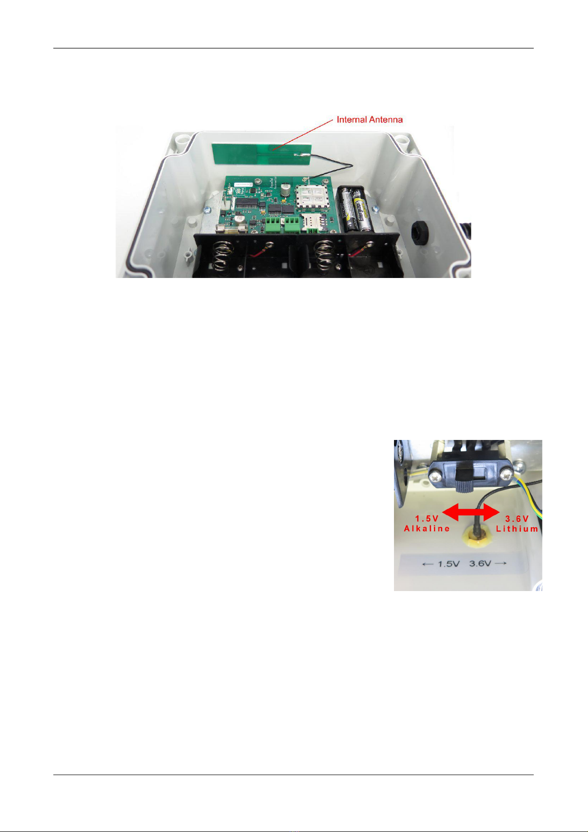
2.2. ANTENNA INSTALLATION..................................................................................................................................................6
2.3. REAL TIME CLOCK BATTERY INSTALLATION .......................................................................................................................6
2.4. D CELL VERSION BATTERY INSTALLATION .........................................................................................................................6
2.4.1. Battery Life.........................................................................................................................................................6
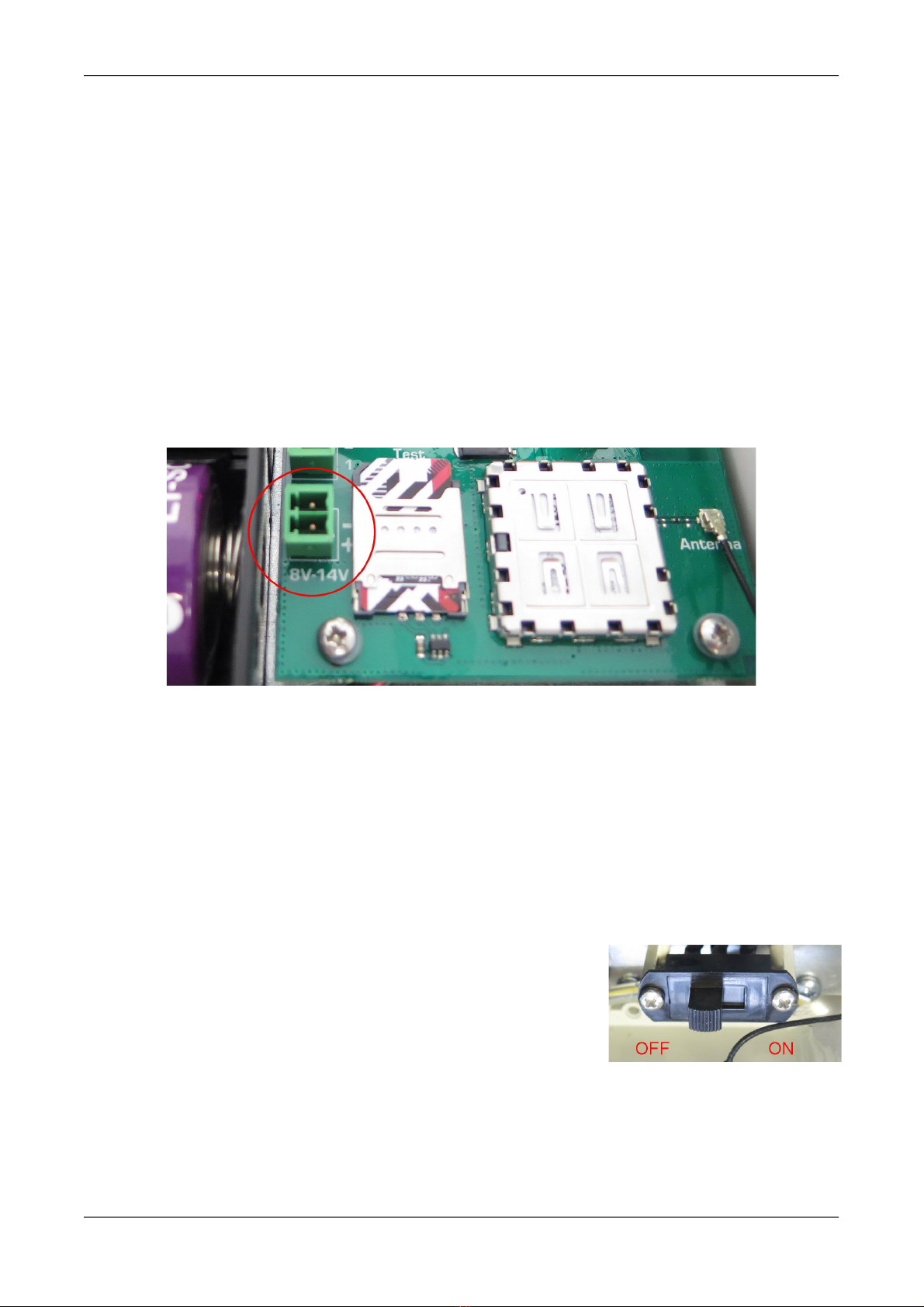
2.5. E TERNAL POWER SUPPLY WITH D CELLS AS BACKUP ........................................................................................................7
2.6. 12V SOLAR PANEL VERSION...........................................................................................................................................7
2.7. INITIAL INDICATIONS ........................................................................................................................................................8
2.7.1. Network Signal Strength Indications..................................................................................................................8
2.8. TELEMETRY SETUP..........................................................................................................................................................9
2.9. DOWNLOADING THE PC SOFTWARE AND USB DRIVER FROM THE AQUAREAD® WEBSITE .........................................................9
2.10. SOFTWARE INSTALLATION...............................................................................................................................................9
2.11. DRIVER INSTALLATION...................................................................................................................................................9
2.12. CONNECTING THE AQUATELEMETRY TO A PC.................................................................................................................10
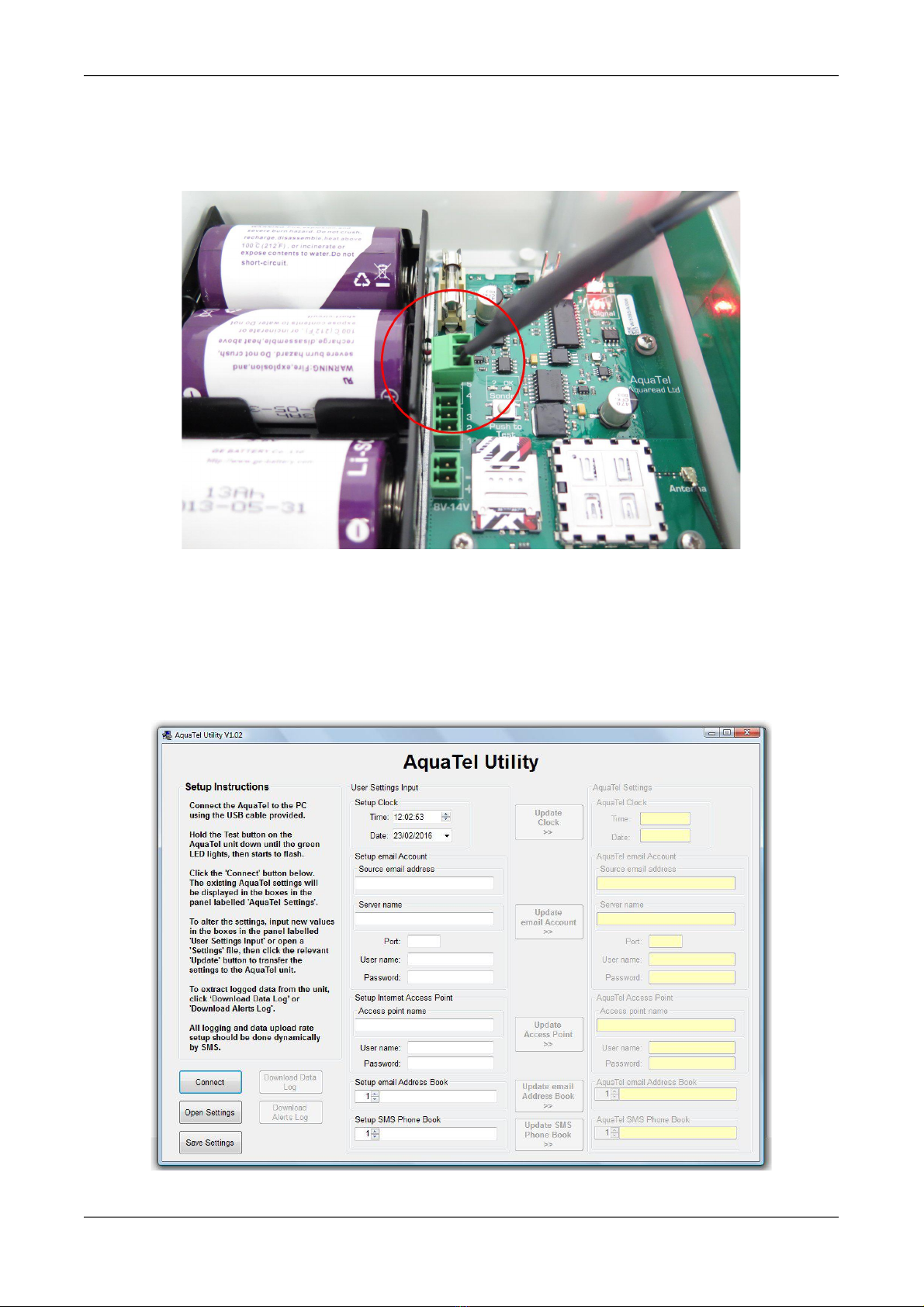
2.13. RUNNING THE PC UTILITY...........................................................................................................................................10
2.14. AQUATELEMETRY SETUP SCREEN OVERVIEW.................................................................................................................11
2.14.1. On Screen elp...............................................................................................................................................11
2.15. INITIATING PC MODE..................................................................................................................................................11
2.16. CLOCK SETUP.............................................................................................................................................................12
2.17. EMAIL ACCOUNT SETUP...............................................................................................................................................12
2.18. INTERNET ACCESS POINT SETUP....................................................................................................................................12
2.19. EMAIL ADDRESS BOOK SETUP......................................................................................................................................13
2.20. SMS PHONE BOOK SETUP...........................................................................................................................................13
2.20.1. Phone Book Format........................................................................................................................................13
2.21. SAVING AND RETRIEVING YOUR SETTINGS.....................................................................................................................14
2.22. LEAVING PC MODE....................................................................................................................................................14
2.23. TELEMETRY TESTING...................................................................................................................................................14
3. AQUATELEMETRY SYSTEM DEPLOYMENT......................................................................................................16
3.1. IDENTIFYING THE LEVELINE® SONDE TYPE .....................................................................................................................16
3.2. DEPLOYING THE SONDE..................................................................................................................................................16
3.2.1. Deployment in Open Water..............................................................................................................................16
3.2.2. Deployment Depth............................................................................................................................................16
3.3. DEPLOYING THE AQUATELEMETRY UNIT..........................................................................................................................17
3.3.1. AquaTelemetry Wiring......................................................................................................................................17
3.3.2. Antenna Installation.........................................................................................................................................18
3.3.3. Applying Power (D Cell Version).....................................................................................................................18
3.3.4. Solar Panel Installation....................................................................................................................................18
3.3.5. Activating the Solar Charge Controller...........................................................................................................18
4. FINAL SETUP AND TEST...........................................................................................................................................20
4.1. TESTING THE INSTALLATION............................................................................................................................................20
4.2. SETTING UP THE MEASUREMENT AND LOGGING PARAMETERS (ADMINISTRATORS ACCESS ONLY).............................................21
4.2.1. Settings Shorthand............................................................................................................................................21
4.2.2. Setting the Logging Interval.............................................................................................................................21
4.2.3. Setting the Log Upload Interval.......................................................................................................................22
4.2.4. Setting the Initial Upload Time........................................................................................................................22
4.2.5. Setting the Site ID.............................................................................................................................................22
4.2.6. Setting the Real Time Clock Offset...................................................................................................................22
4.2.7. Zeroing the Level Value....................................................................................................................................23
4.2.8. Clearing the AquaTelemetry Memory..............................................................................................................23
4.3. SETTING UP THE ALERT PARAMETERS..............................................................................................................................23
4.3.1. Setting Level Alerts...........................................................................................................................................24
4.3.2. Setting the Rate Alert........................................................................................................................................24
4.3.3. Setting the Alerts Logging Interval...................................................................................................................24
4.3.4. Log Upload Interval in Alert Mode..................................................................................................................25
© 2020 Aquaread® Ltd. www.aquaread.com Page 3 of 34

AquaTelemetry Instruction Manual 10401-01193 Rev H
4.4. PHONE BOOK MAINTENANCE..........................................................................................................................................25
4.4.1. Phone Book Query (Administrators only)........................................................................................................25
4.4.2. Setting a Phone Book Entry (Administrators Only).........................................................................................25
4.4.3. Deleting a Phone Book Entry (Administrators Only).......................................................................................26
5. REQUESTING DATA BY SMS...................................................................................................................................27
5.1. REQUESTING CURRENT CONFIGURATION (WILL RESPOND TO ANY REGISTERED SMS NUMBER).................................................27
5.2. REQUESTING CURRENT LEVEL AND ALERT STATUS (WILL RESPOND TO ANY NUMBER) ...........................................................27
5.3. REQUESTING AND IMMEDIATE LOG UPLOAD BY EMAIL (WILL RESPOND TO ADMINISTRATORS ONLY) ........................................28
6. DOWNLOADING LOGGED DATA TO A PC..........................................................................................................2
6.1. REGULAR DATA LOG....................................................................................................................................................29
6.2. ALERTS DATA LOG.......................................................................................................................................................29
6.3. CLEARING THE AQUATELEMETRY MEMORY......................................................................................................................30
7. DECLARATION OF CONFORMITY........................................................................................................................30
8. TROUBLESHOOTING.................................................................................................................................................31
. LIMITED WARRANTY...............................................................................................................................................32
9.1. CLEANING PRIOR TO RETURN.........................................................................................................................................32
9.2. DECONTAMINATION CERTIFICATE.....................................................................................................................................33
10. APPENDIX 01. QUICK REFERENCE GUIDE.......................................................................................................34
© 2020 Aquaread® Ltd. www.aquaread.com Page 4 of 34

AquaTelemetry Instruction Manual 10401-01193 Rev H
1. Introduction to the Product
This manual covers the setup and operation of the AquaTelemetry Telemetry system
running software version 1.02+ in association with any LeveLine® Absolute Level Sonde.
1.1. What Does The AquaTelemetry System Do?
The Aquaread® AquaTelemetry system, when used in association with a LeveLine® Mini
Level Sonde forms a data-logging and telemetry system that records water level and
temperature at pre-determined intervals then uploads the logged data periodically via email
to multiple monitoring facilities.
Instantaneous level and temperature data can be requested by SMS. The current water
level and temperature will be returned immediately by SMS. In addition, four level alerts
and one rate-of-change alert can be set to automatically send SMS messages if an alert
condition exists.
2. Setup Prior to Installation
Prior to installing the AquaTelemetry system in the field, the system must have a SIM card
fitted and it must then be set up using a P utility.
2.1. SIM Card Fitting
Prior to installation and fitting of the main batteries, an active SIM card must be fitted to the
unit. The SIM card must not be locked or PIN protected. To install the SIM card, lay the
AquaTelemetry unit flat on a workbench, remove the four corner screws, then remove the
plastic cover. The SIM card socket is located at the bottom left of the circuit board.
Open the SIM card socket cover by sliding it down towards the bottom of the unit then
swinging it up. Fit the SIM card then shut the cover and lock it in place by sliding it towards
the top of the unit. See sequence of photographs below.
Make a note of the phone number registered to the SIM card. You will need this for
setup and communication later.
© 2020 Aquaread® Ltd. www.aquaread.com Page 5 of 34

AquaTelemetry Instruction Manual 10401-01193 Rev H
2.2. Antenna Installation
Standard AquaTelemetry units have a strip antenna attached to the inside of the enclosure
(see photograph below. If your unit has this antenna fitted, please skip the next paragraph.
If your unit is set up for use with an external antenna, there will be an SMA type female
antenna socket fitted to the underside of the enclosure. onnect a suitable GSM antenna
and locate it in a position likely to receive a good network signal.
2.3. Real Time Clock Battery Installation
The AquaTelemetry unit requires two Alkaline 1.5V AAA batteries to supply power to the
real time clock. These batteries will last approximately five years and once fitted, should not
be removed unless being replaced with new. If these batteries are removed, the time
and date will be lost and the real time clock must be reset using the PC utility.
2.4. D Cell Version Battery Installation
If you have specified the D ell version of this equipment, the
main power for the system is supplied by either two pairs of
Primary Lithium-thionyl hloride 3.6V D cells or two pairs of
Alkaline 1.5V D cells (international size reference: UM1/R20/D).
A selector switch allows the battery type to be chosen. The
photograph shows the switch set to the 1.5V (Alkaline battery)
position.
ENSURE THE CORRECT BATTERY TYPE IS SELECTED
BEFORE INSERTING THE BATTERIES
2.4.1. Battery Life
Battery life varies greatly with battery type selected, logging rate, cellular signal strength,
temperature and the number of emails programmed to transmit.
With normal use (reasonable signal strength, 15 minute logging rate and email upload once
per 24 hours hours), a set of four Lithium-thionyl hloride batteries should last around 9 -
12 months.
With normal use, one set of good quality Alkalline batteries (such as Duracell Ultra) should
last 4 – 6 months. The capacity of Alkaline batteries varies by up to 50% with temperature,
so expect a shorter battery life in the winter months.
© 2020 Aquaread® Ltd. www.aquaread.com Page 6 of 34

AquaTelemetry Instruction Manual 10401-01193 Rev H
Battery voltage is output with all logged data and also in the 'Level' SMS message. Battery
voltage should be monitored periodically by the system administrator to ensure the
batteries do not go flat leaving the system inoperative.
When the reported battery voltage drops to 4.0V (Alkaline) or 6.0V (Lithium), the batteries
should be replaced.
Always replace all four batteries together. If old and new batteries are mixed, the new
batteries will discharge rapidly and data may be lost.
2.5. External Power Supply with D Cells as Backup
If you have specified the D ell version of this equipment, you may choose to supply
primary power from an external 8V – 14V supply, and fit the D cells as a secondary backup.
In this case, wire your external power supply to the terminals adjacent the SIM card,
marked 8V-14V. Polarity is also indicated.
The external power supply should be capable of supplying a peak load of 2A during
transmission of SMS messages and emails, although normal current consumption between
transmissions is less than 5mA.
In the event that the external power supply fails, the internal D cells will automatically take
over.
2.6. 12V Solar Panel Version
If you have specified the 12V Solar Panel version of this equipment, the system will come
complete with a 12V battery and Solar harge ontroller pre-installed and wired.
In order to apply power to the system, simply slide the
ON/OFF switch to the ON position. With the solar panel
correctly fitted and orientated, and with normal use, the 12V
battery should remain permanently charged.
Battery voltage is output with all logged data and also in the 'Level' SMS message. The
voltage should be monitored by the user. If the reported battery voltage drops below 10.8V
the solar panel may need cleaning or maintenance or the 12V battery may need replacing.
Average life for the 12V battery is five years.
© 2020 Aquaread® Ltd. www.aquaread.com Page 7 of 34

AquaTelemetry Instruction Manual 10401-01193 Rev H
2.7. Initial Indications
Within a few seconds of the main batteries being installed (or in the case of the solar power
version, the power switch being set to ON), the left hand (red) LED of the signal strength
LEDs will start to flash. This indicates the system is initialising.
2.7.1. Network Signal Strength Indications
After several seconds more, the mobile network signal strength will be indicated on the
LEDs in accordance with the table below.
LED Indication Network Signal Strength
Red LED flashing No network signal
Red LED only on Signal strength 1/5
Red and Yellow LEDs on Signal strength 2/5
Yellow LED only on Signal strength 3/5
Yellow and Green LEDs on Signal strength 4/5
Green LED only on Signal strength 5/5
Ideally, for reliable communications, the unit should be positioned so that a minimum signal
strength of 3/5 (yellow LED only on) is achieved.
After a short time, the unit will enter standby mode. In this condition the signal strength
LEDs will switch off, but the yellow LED will give a very brief flash every five seconds.
To repeat the signal strength test, briefly press the Test Button. The signal LEDs will light
up for several seconds to indicate the signal strength before the unit returns to standby
mode.
© 2020 Aquaread® Ltd. www.aquaread.com Page 8 of 34

AquaTelemetry Instruction Manual 10401-01193 Rev H
2.8. Telemetry Setup
Before the AquaTelemetry unit will communicate, it must be programmed with some basic
information concerning authorised SMS numbers, email addresses and email server
details.
In order to program the unit, it must be connected to a P running AquaTel Setup Utility
software.
The Aqua el Setup Utility is designed to run under Microsoft® Windows® XP® or later on a
stand-alone P with a minimum screen resolution of 1024 x 768 and an available USB 2.0
socket.
Do not connect the AquaTelemetry USB cable to your PC until after the software and
USB driver have been installed.
2.9. Downloading the PC Software and USB Driver from the Aquaread® website
The Aqua el Setup Utility Software is available for download using the following link:
http://www.aquaread.com/software-downloads
From the Aquaread® Downloads page, select 'AquaTel Setup Utility'. The software will be
downloaded as a .ZIP file.
2.1 . Software Installation
Unzip the downloaded .ZIP file into a temporary directory. Browse the temporary directory
and click on ‘setup.exe’. You will be given the usual Windows® security warnings. Allow the
software to install. Once installed, the Aqua el Setup Utility will run automatically.
To communicate with the AquaTelemetry unit, two further software ‘drivers’ need to be
installed. These are the 'AquaTel' driver and a 'USB Serial Port' driver.
2.11. Driver Installation
onnect the AquaTelemetry USB cable to your P . The ‘Found New Hardware’ wizard on
your P should activate automatically.
Different versions of Windows® react to plugging USB devices in differently. Earlier versions
will give you the option to 'locate and install driver software'. If this happens, direct
Windows® to your temporary directory containing the unzipped download.
If your version of Windows® tries to search the Internet or 'Windows Update' for the drivers,
stop the search and direct Windows® to your temporary directory.
If Windows® reports a problem installing the drivers, go to your Windows® Device
Manager, locate the 'AquaTel' device and update the driver forcing Windows® to search
your temporary directory for the driver. Repeat this process for the USB Serial Port.
© 2020 Aquaread® Ltd. www.aquaread.com Page 9 of 34

AquaTelemetry Instruction Manual 10401-01193 Rev H
2.12. Connecting the AquaTelemetry to a PC
Now connect the AquaTelemetry USB cable to the AquaTelemetry unit (sockets 4, 5 & 6)
as shown in the photograph below.
2.13. Running the PC Utility
If the P utility did not start automatically after installation, select ►Aquaread then
►Aqua el Setup Utility from your Programs menu. The Setup Utility screen will appear:
If you are using a laptop or notebook with a small screen, the window can be resized by
dragging the bottom right hand corner.
© 2020 Aquaread® Ltd. www.aquaread.com Page 10 of 34

AquaTelemetry Instruction Manual 10401-01193 Rev H
2.14. AquaTelemetry Setup Screen Overview
The AquaTelemetry Setup screen allows you to setup the following parameters:
•The AquaTelemetry unit's real time clock
•An email account for data uploads
•A mobile internet access point
•Up to fifteen email addresses
•Up to fifty SMS numbers
In addition, the software allows you to download logged data directly from the
AquaTelemetry unit and save that data to a file on your P .
2.14.1. On Screen Help
Help has been provided in this software in the form of ‘Tool Tips’. If you want to know what
a control button does or what a data box displays, simply move your mouse pointer over
the item in question. A Tool Tip will appear after a few seconds to give you more
information.
2.15. Initiating PC Mode
To initiate P mode on the AquaTelemetry unit, ensure the batteries are fitted and the
yellow LED is giving a single flash every five seconds (i.e. the unit is in standby mode).
Press and hold the 'Push to Test' button beside the USB cable
connector until the Green LED lights up and starts to flash. Now,
within 30 seconds, click the ' onnect' button located on the left of the
P screen just below the Setup Instructions.
The following warning box will appear to remind you to put the AquaTelemetry unit into P
mode.
lick on OK. The P will communicate with the AquaTelemetry unit and display the
AquaTelemetry unit's live clock data in the AquaTelemetry lock window on the right hand
side of the screen. In addition, if the AquaTelemetry unit has been previously set up, the
email and phone book settings currently held in the unit will be displayed.
To change any AquaTelemetry settings, enter the revised setting into the relevant box in
the 'User Setting Input' column, then click the relevant button to transfer the data to the
AquaTelemetry unit.
© 2020 Aquaread® Ltd. www.aquaread.com Page 11 of 34

AquaTelemetry Instruction Manual 10401-01193 Rev H
2.16. Clock Setup
The clock setup windows are shown below.
The boxes within the window to the left labelled 'Setup lock' show the current time and
date from your P . You can override/change this time and date if you want to by directly
altering the values within the boxes.
The boxes within the window to the right labelled 'AquaTelemetry lock' show the time and
date of the connected AquaTelemetry unit's master clock (without any offset applied). To
synchronise the master clock in the AquaTelemetry unit to the time shown in the 'Setup
lock' window, click the 'Update lock' button.
Once the unit is deployed, an offset to correct for daylight saving time can be applied and
removed by sending a special SMS message. This is detailed in section 3 of this manual.
2.17. Email Account Setup
In the group of boxes labelled 'Setup email Account', there are five pieces of information
you must input. These are:
•Source email Address: The email address from which you wish to send emails
•Server Name: The name of your SMTP server
•Port: The SMPT port number
•User Name: Your SMPT user name
•Password: Your SMPT password
This information should be obtained from your Internet Service Provider. If you do not want
to send logged data by email, leave all fields blank.
When you have filled in all five boxes, click the 'Update email Account' button and ensure
the data is echoed in the boxes on the right of the screen.
2.18. Internet Access Point Setup
In the group of boxes labelled 'Setup Internet Access Point', there are three pieces of
information you must input. These are:
•Access Point Name: The access point name
•User Name: The access point user name
•Password: The access point password
This information should be obtained from the Mobile Network Provider that supplied the
SIM card. If you do not want to send logged data by email, leave all fields blank.
When you have filled in all three boxes, click the 'Update Access Point' button and ensure
the data is echoed in the boxes on the right of the screen.
© 2020 Aquaread® Ltd. www.aquaread.com Page 12 of 34

AquaTelemetry Instruction Manual 10401-01193 Rev H
2.19. Email Address Book Setup
In this field, input up to fifteen email accounts to which you wish logged data to be sent.
There is an index number on the left of the entry field along with an up/down arrow control
to allow you to scroll through all ten addresses. If you do not want to send logged data by
email, leave all ten email addresses blank.
When you have entered all the required email addresses, click the 'Update email Address
Book' button and ensure the data is echoed on the right of the screen.
2.2 . SMS Phone Book Setup
SMS is the primary communication medium of the AquaTelemetry unit. It is used to
configure the system and to retrieve instantaneous level and alerts data. All SMS numbers
registered in the unit will also receive rate and level alerts as they occur in real time.
The AquaTelemetry unit allows the input of two classes of SMS phone number;
Administrator and User.
Any SMS numbers designated as Administrators can make changes to the AquaTel's setup
parameters and phone book by SMS.
Any SMS numbers designated as Users, can only access information and setup
parameters from the AquaTelemetry unit, they can not make any changes.
All SMS numbers registered will receive level and rate alerts.
Any SMS number, whether registered or not, can request level and alert data at any time.
Don't worry if you do not have all the required SMS numbers to hand at the time of initial
setup. SMS numbers can be added, altered and deleted later on by SMS by any registered
Administrator.
Be very careful when deciding which numbers to configure as administrators.
Administrators have the power to change all settings by SMS, including adding and
removing other SMS numbers from the SMS Phone Book.
It is essential to input at least one Administrator SMS number in order to allow
configuration of the unit. Without at least one Administrator, you will be unable to set
the unit up by SMS.
2.2 .1. Phone Book Format
SMS numbers MUST be entered in the international format including the country code but
excluding the leading + and any spaces.
Each SMS number must also be preceded by either an 'A' or a 'U' to indicate whether that
number belongs to an Administrator or a User.
For example, to enter the UK mobile number 7881 523 164 as an Administrator, you
must enter:
A447881523164
© 2020 Aquaread® Ltd. www.aquaread.com Page 13 of 34

AquaTelemetry Instruction Manual 10401-01193 Rev H
To enter the French (country code 33) mobile number 07954 256 142 as a User, you must
enter:
U337954256164
So, to recap, enter an A or a U, followed by the mobile number in international format
excluding the leading + and all spaces.
When you have entered all the required SMS numbers, click the 'Update SMS Phone Book'
button and ensure the data is echoed on the right of the screen.
2.21. Saving and Retrieving Your Settings
When you have completed all your user settings and phone book, you can save them by
clicking the 'Save Settings' button. You will prompted for a file name, which will
automatically be given the extension .ats (AquaTelemetry Settings).
Subsequently, the settings can be retrieved by clicking the 'Open Settings' button and
selecting the appropriate file.
2.22. Leaving PC Mode
When all the necessary data has been input and transferred to the AquaTelemetry unit,
click the 'Disconnect' button on the screen then momentarily press the test button on the
AquaTelemetry unit. The AquaTelemetry unit will revert to standby mode.
If you click the 'Disconnect' button on the screen but do not push the button on the
AquaTelemetry unit, the AquaTelemetry unit will enter standby mode automatically after 30
seconds.
2.23. Telemetry Testing
Now that the telemetry parameters have been set up, communications should be tested. To
do this, use a mobile phone that has its number stored in the AquaTelemetry unit's Phone
Book and send a message to the phone number that is registered to the AquaTelemetry
unit's SIM card.
The message should contain a single word: config.
Watch the signal LEDs on the AquaTelemetry unit. As soon as you have sent the message,
the AquaTelemetry unit should leave standby mode and display the network signal level on
the LEDs in accordance with the table shown in section 2.7.
If all is well, the AquaTelemetry unit will reply with the two 'Settings' SMS messages,
detailed below, before returning to standby mode:
Message 1 contents Brief explanation
SETTINGS UPDATE Message heading
SITE = XXXXXXXXXXXXXXXX Site identifier (default is AquaTel's serial number)
TIME OFFSET=+HH:MM Daylight saving offset applied to the master clock
UPLD LOG EVERY=HH:MM Log upload by email interval
FIRST UPLD AT=HH:MM Time first log is uploaded by email each day
SMS HK EVERY=HH:MM Interval at which SMS messages are read
LOG INTERVAL=HH:MM Normal data logging interval
© 2020 Aquaread® Ltd. www.aquaread.com Page 14 of 34

AquaTelemetry Instruction Manual 10401-01193 Rev H
Message 2 contents Brief explanation
SETTINGS UPDATE Message heading
SITE = XXXXXXXXXXXXXXXX Site identifier (default is AquaTel's serial number)
ALERT LOG INTERVAL=H:MM Shorter logging interval when an alert is active
L1 ALERT =+XXXXX Alert level 1 in mm
L2 ALERT =+XXXXX Alert level 2 in mm
L3 ALERT =+XXXXX Alert level 3 in mm
L4 ALERT =+XXXXX Alert level 4 in mm
RATE ALERT=+XXXX Rate of change alert in mm/minute
The reception of these two messages will prove that the SIM card is properly fitted and that
the communication section of the system is working correctly.
The individual settings can be set up to suite your application now, or the setup can be
done at a later date, after installation of the equipment on site.
See section 4.2 for full details.
© 2020 Aquaread® Ltd. www.aquaread.com Page 15 of 34

AquaTelemetry Instruction Manual 10401-01193 Rev H
3. AquaTelemetry System Deployment
Prior to deployment of the AquaTelemetry unit, be sure to connect it to a P running
AquaTelemetry Utility Software and to set up the telemetry parameters. If you do not set
the AquaTelemetry unit's telemetry up, you will not be able to communicate with it
when it has been deployed in the field!
3.1. Identifying the LeveLine® Sonde Type
It is extremely important to identify your LeveLine® Sonde type prior to deployment. The
AquaTelemetry unit is designed to work with LeveLine® Absolute (ABS) type sondes only.
Gauge type sondes will not give correct level readings.
Also, deploying a water level sonde deeper than its maximum rating will cause overload
damage.
To identify your LeveLine® sonde model and depth rating, remove the
end cap and look at the label fitted into the end of the sonde. The label
will show the maximum depth rating and the word ABS or GAUGE.
After identifying your sonde rating, replace the end cap and follow these
simple rules:
•Never use a GAUGE type sonde with the AquaTelemetry unit.
•Never deploy a water level sonde deeper than its maximum rating.
•Never deploy a water level sonde where the water is liable to freeze.
3.2. Deploying the Sonde
The diagram to the right shows a typical borehole installation with the sonde
submerged below the minimum water level line.
Please note, in this case the well or borehole cap must be ventilated in order
to allow the water level to rise and fall freely.
Important: Always install the LeveLine® sonde vertically with the
cable at the top as shown in the diagram. Water level measurements are
made at the row of holes positioned around the bottom of the end cap. Use
these holes as a reference point for measuring deployment offsets or when
zeroing the level (see section 4.2.7) if required.
3.2.1. Deployment in Open Water
If the sonde is to be deployed in open water (i.e. a river, lake or the sea), a
length of plastic pipe should first be mounted, then the sonde should be
suspended within the pipe, but not on the bottom where it could become
buried by silt. This will protect the sonde from currents, wave action, and
debris.
3.2.2. Deployment Depth
Sondes must not be submerged below twice their rated depths. If any sonde is submerged
past this limit, the pressure sensor will burst and will require replacing. Damage of this kind
is not covered by your warranty.
© 2020 Aquaread® Ltd. www.aquaread.com Page 16 of 34

AquaTelemetry Instruction Manual 10401-01193 Rev H
3.3. Deploying the AquaTelemetry Unit
The AquaTelemetry unit is designed to be used outdoors and is rated to IP67, that is to say
it is waterproof but it is not designed for submersion. You may notice a small hole on the
base of the unit. This is a waterproof vent for the internal barometric sensor. Do not poke
anything in this hole! Doing so will cause major damage to the vent’s waterproof
membrane and invalidate your warranty.
The AquaTelemetry unit includes a barometric pressure sensor. For this reason, any
secondary housing MUST be vented in order to allow the barometric pressure sensor
to operate correctly. If the AquaTelemetry unit is mounted inside a secondary sealed
housing, incorrect level measurements will be recorded.
If you are mounting the AquaTelemetry unit directly, without the use of the tamper-proof
bracket, remove the main box cover then screw the AquaTelemetry box directly to any
suitable surface by passing screws through the four corner mounting holes.
If you are mounting the AquaTelemetry unit in a tamper-proof bracket, screw the bracket to
a suitable surface then remove the main box cover and slide the AquaTelemetry unit into
the bracket.
If the AquaTelemetry unit has an internal antenna, the unit must be mounted in a position
where it is likely to receive a good network signal. Avoid mounting the unit too low to the
ground.
The side of the unit where the internal antenna is mounted must be kept clear of any
external obstructions which may affect radio signal reception. Do not mount the unit
with the antenna side up against any solid object such as a wall or tree.
3.3.1. AquaTelemetry Wiring
Before making connections to the AquaTelemetry unit, remove all the D size primary
batteries. DO NOT remove the two AAA clock batteries. In the case of the 12V solar
powered version, set the power switch to the OFF position.
The sonde connections to the AquaTelemetry unit are made on the circuit board using the
removable connector headers. The sonde cable should be fed through the waterproof gland
in the base of the unit and made off as shown below.
© 2020 Aquaread® Ltd. www.aquaread.com Page 17 of 34

AquaTelemetry Instruction Manual 10401-01193 Rev H
Once the sonde cable has been made off, ensure the cable gland is tightened to prevent
water ingress.
3.3.2. Antenna Installation
If the unit is configured for use with an external antenna, a suitable antenna should be
connected to the mating socket on the base of the unit and mounted in a position with good
access to the mobile phone network.
3.3.3. Applying Power (D Cell Version)
Replace the D size primary batteries. Do not fit the main box cover until after the installation
has been tested as detailed in section 4.1 below.
3.3.4. Solar Panel Installation
If you are installing a solar panel with this system, a Universal Side-of-Pole mount will have
been supplied with the panel.
The solar panel should be pole mounted using the adjustable brackets provided and
orientated due south (in the northern hemisphere) at a suitable angle to the sun. This angle
will obviously vary with the time of year and periodic adjustments may optimise the panel's
output, especially during the winter months. When mounting the solar panel, follow the
instruction sheet enclosed with the mounting kit.
When the solar panel has been installed, connect the cable to the mating socket on the
base of the Aqua Telemetry unit.
3.3.5. Activating the Solar Charge Controller
After attaching the solar panel plug to the socket, slide the power switch to the ON position.
If there is any sunlight striking the solar panel at all, the PV LED on the controller should
illuminate solidly indicating that the solar panel is delivering voltage to the system.
The LOAD LED should be off. If the LOAD LED is illuminated, briefly push the on/off button
on the controller to switch it off.
© 2020 Aquaread® Ltd. www.aquaread.com Page 18 of 34

AquaTelemetry Instruction Manual 10401-01193 Rev H
The four LEDs above the on/off button indicate the charge state of the 12V battery. The
more LEDs that are illuminated, the better the charge state.
If the first LED is flashing slowly, this indicates that the 12V battery is completely
discharged. In this case, provided the solar panel is clean and properly orientated, it is a
sunny day and the PV LED is on, the battery should receive a full charge within a few
hours.
Alternatively, the 12V battery can be charged by attaching the optional lead-acid battery
charger to the charging socket located above the battery.
WARNING: USE ONLY THE RECOMMENDED BATTERY CHARGER. USE OF OTHER
CHARGER TYPES MAY DAMAGE THE BATTERY.
Do not fit the main box cover until after the installation has been tested as detailed in
section 4.1 below.
© 2020 Aquaread® Ltd. www.aquaread.com Page 19 of 34

AquaTelemetry Instruction Manual 10401-01193 Rev H
4. Final Setup and Test
4.1. Testing the Installation
When the installation is complete and the primary power applied, the AquaTelemetry unit
will automatically register with the mobile phone network. After registration, the
AquaTelemetry unit will display the network signal strength on the signal LEDs. The unit will
then enter a low power standby mode where it will wait for the first scheduled logging time
to occur or for an SMS message to be received. When the unit enters standby mode, the
yellow LED will flash once briefly every five seconds.
When in standby mode, the unit can be woken up by momentarily pressing the test button
located near the sonde connections. Do not hold the test button down as this will cause
the unit to enter PC Mode. When the button is pressed, the AquaTelemetry unit will
display the network signal strength on the signal LEDs in accordance with the table shown
in section 2.7.1. After several seconds, the unit will return to standby mode.
heck the unit is receiving a good network signal. The signal value reported on the LEDs is
in the range 0 – 5. A minimum signal strength of 3 is recommended for reliable operation. If
the signal strength is less than 3, try repositioning the unit, or if applicable, the external
antenna or using a more sensitive model.
Once the signal level is satisfactory, test the operation of the system by sending the
AquaTelemetry unit an SMS message.
The message should contain a single word: level.
Watch the signal LEDs on the AquaTelemetry unit. As soon as you have sent the message,
the AquaTelemetry unit should leave standby mode and display the network signal level on
the LEDs in accordance with the table shown in section 2.7.1.
If all is well, the AquaTelemetry unit will reply with the 'Level' SMS messages, detailed
below, before returning to standby mode:
Level Message content Brief explanation
SITE= XXXXXXXXXXXXXXX Site identifier
LEVEL AT HH:MM DD/MMM/YY urrent time and date of reading
LEVEL=XX.XXXm urrent water level over sonde
TEMP=XX.XX urrent sonde temperature
RATE= +XXXXmm/min Rate of level change since last reading
ALERT= NONE (or LEVEL X or RATE) Alert status
BATTERY=XX.XX V Battery voltage
heck the data received in the text message is correct with reference to the following
paragraphs.
1. The site identifier will be either the AquaTel's serial number or, if it has been set up,
a valid site name.
2. The time and date should be correct for the instant the message was sent. If the time
and date are not correct, the real time clock in the AquaTelemetry unit must be reset
using the AquaTel P Utility as detailed in section 2.16.
© 2020 Aquaread® Ltd. www.aquaread.com Page 20 of 34
This manual suits for next models
1
Table of contents
Other Aquaread Measuring Instrument manuals