aquilar AquiNet User manual

AquiNet AquiNet
Fieldbus Monitoring
System
INSTALLATION
INSTRUCTIONS

Please read these
instructions carefully
and keep them in a
safe place (preferably
close to the module)
for future reference.
These instructions
must be followed
carefully to ensure
proper operation.
AquiNet
Fieldbus Network System
A. GENERAL INFORMATION
Zone Control Modules (ZCM) can be added to any leak detection device with volt free contacts.
When the relay changes over, a signal is sent via the fieldbus network to a master generator.
Each master generator can monitor up to 100 ZCM's. Multiple generators can also be linked to
create very large networks. The master generator interfaces with a touch screen panel that
runs the graphical user interface (GUI) which displays alarms and current system status. The
GUI can be tailored specifically to the client’s requirements.
LEAK DETECTION SOLUTIONS
Aqui
N
et
Weights & Measures House, 20 Barttelot Road,
Horsham, West Sussex RH12 1DQ
+44 (0) 1403 216100
www.aquilar.co.uk
1
INSTALLATION ITEMS
(NOT SUPPLIED)
• Wall fasteners for surface mounting.
TOOLS REQUIRED
• Drill or hole punch for electrical
conduit entries
• Phillips (cross-head) screwdriver
• Small at-head screwdriver
STORAGE
Keep the module in a dry place prior to
installation to avoid possible damage to
internal components.
AQUINET
230Vac. 3A unswitched fused spur
OUTPUTS
BACnet / IP / Modbus / TCP / Optional volt
free contacts
B. PRODUCT INFORMATION TFT
7” LCD 32K Colour 800x480 pixels.
NEMA 4 / IP65 front panel.
Resistive analogue touchscreen
Software stored in non-volatile ash memory
ENCLOSURE
H 330 x W 292 x D87mm
C. TOPOLOGY
The topology of a bus system is the denition
of which type of cable routing is allowed.
AquiNet features a completely free topology
Star
Ring Line
allowing the network to be established as a
line, ring, star or a combination of these.
AquiNet
Fieldbus Network System
LEAK DETECTION SOLUTIONS
Weights & Measures House, 20 Barttelot Road,
Horsham, West Sussex RH12 1DQ
+44 (0) 1403 216100
www.aquilar.co.uk
2
m
AT-G-ALERT
Refrigerant Leak
Detectors
Two Wire, Open Topolgy, Cabling
Bacnet/IP/Modbus/TCP/Webserver
Aquinet System
Comprising of
7” Touchscreen TFT
BACnet Comtroller
Fieldbus Generator
Email
Mobile Phone
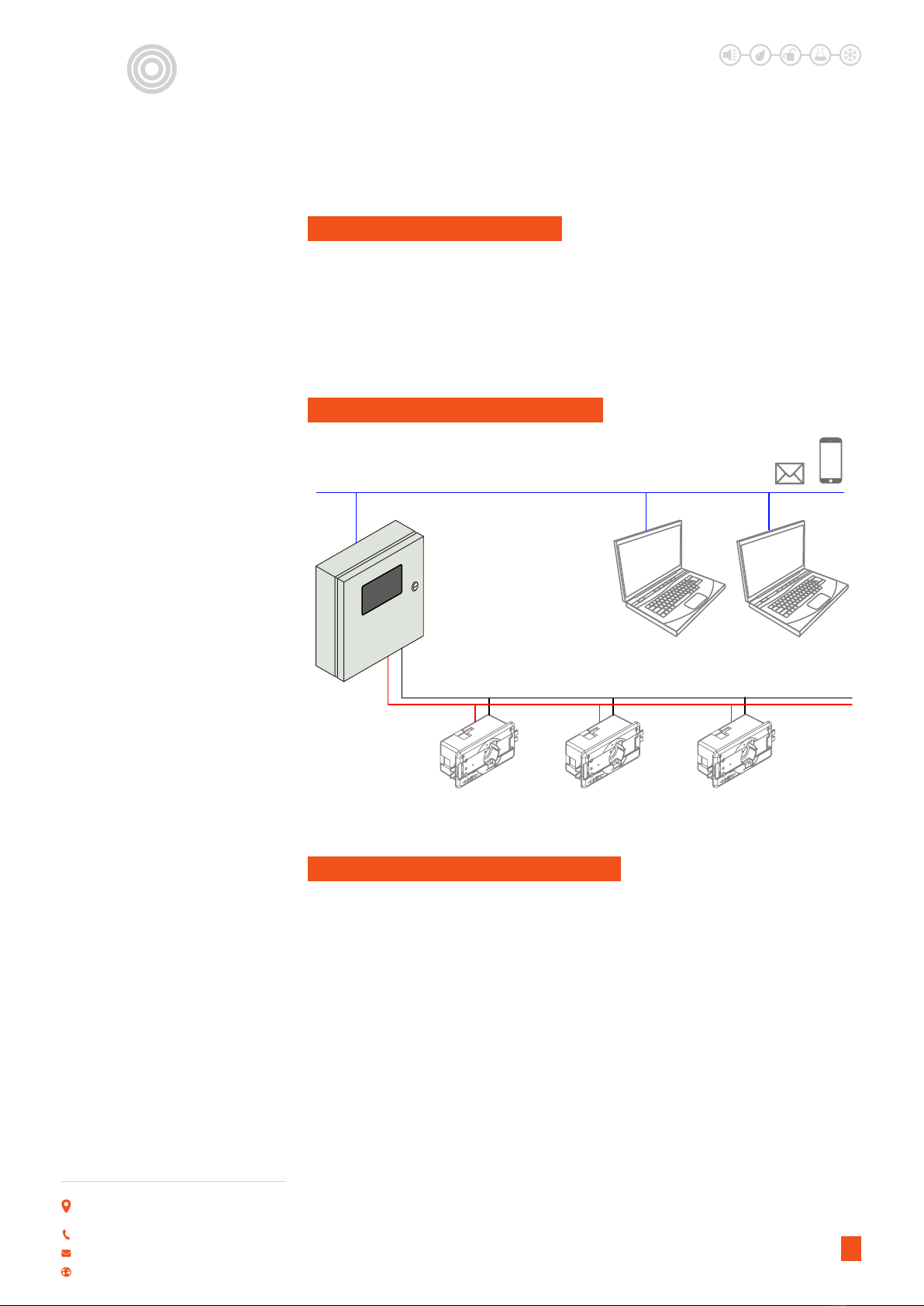
E. TYPICAL SYSTEM SCHEMATIC
F. CABLE AND INSTALLATION TIPS
When planning the installation, a generic
Bus cable can be used, however, it is better
to use a twisted cable in order to prevent
electrical noise from aecting one conductor
more than the other and thereby creating an
unbalanced system. In the case of very noisy
installations (with sources such as contactors,
inductive loads etc) we recommend the use of
a shielded cable.The table below can be used
to nd the right cable. This can easily carried
out by considering the maximum distance
between the main panel and the furthest
module in the installation and checking the
table below.
Aqui
N
et
D. TYPICAL INSTALLATIONS
Central monitoring of multiple refrigerant
gas sensors (AT-G-ALERT) can be achieved
by tting an I/O module to one of the volt
free contacts. Each sensor is then connected,
using the open topology, to the AquiNet
panel. The built in touch screen will display
alarm status and alarms according to client’s
requirements. Multiple water leak detection
systems, such as the AT-SZA / AT-MZA can
be tted with I/O modules to provide a cost
eective network solution.
The values shown in the table have
been calculated considering a balanced
distribution of the modules on the Bus.
Installations where most of the modules
are placed at the end of the network may
be critical and this is not recommended
(the table is not valid in this case). The
values shown in the table are also suitable
for installations where the majority of the
modules are placed at the beginning of the
network (close to the main panel); this type of
connection represents the best conguration
to guarantee the best performance of the
system.

AquiNet
Fieldbus Network System
LEAK DETECTION SOLUTIONS
Weights & Measures House, 20 Barttelot Road,
Horsham, West Sussex RH12 1DQ
+44 (0) 1403 216100
www.aquilar.co.uk
3
TABLE OF CABLE SECTIONS
Max Current
Consumption
Cable Sizes
0.75mm2(AWG 19),
twisted
1mm2(AWG 17),
twisted
1.5mm2 (AWG 15),
twisted
450mA 50m 70m 100m
350mA 65m 90m 130m
300mA 75m 100m 150m
250mA 90m 120m 180m
200mA 115m 150m 230m
150mA 150m 200m 300m
100mA 225m 300m 450m
50mA 450m 600m 900m
It is recommended to select cables according
to the length end consumption shown
in the table above. It is also advisable to
use polyethylene conductor insulation to
have lower cable capacitance. The total
consumption of all the modules supplied by
G. INSTALLATION ON
EXISTING CABLES
If the installation uses existing cables, it
is important to verify the cross section of
conductors according to the above cable
section table.Once the cable size is checked,
it is important to ensure that there is no
leakage between the two conductors and,
also, no leakage from the conductors to
ground or shield.The best method of leakage
testing before connecting any modules is to
use an insulation tester (min. 500 V) to verify
a resistance higher than 100.000 kΩ.
H. CABLE ROUTING
The cable is a signal cable and it should,
therefore, be routed as such. This means that
it is better to keep it separate from power
cables, high energy noise sources such as
contactors, switched inductive loads etc.
However, if there are no other alternative
possibilities, the routing of the cable may
pass close to power cables. Should the
power cables be very noisy, we suggest using
shielded cables.
Aqui
N
et
the Bus and the cable resistance aect the
voltage of the Bus.The drop in Bus voltage
might cause the modules placed far from
the main panel to not work correctly. The
modules used with the AquiNet system draw
a maximum of 2mA each.
AquiNet
Fieldbus Network System
LEAK DETECTION SOLUTIONS
Weights & Measures House, 20 Barttelot Road,
Horsham, West Sussex RH12 1DQ
+44 (0) 1403 216100
www.aquilar.co.uk
4
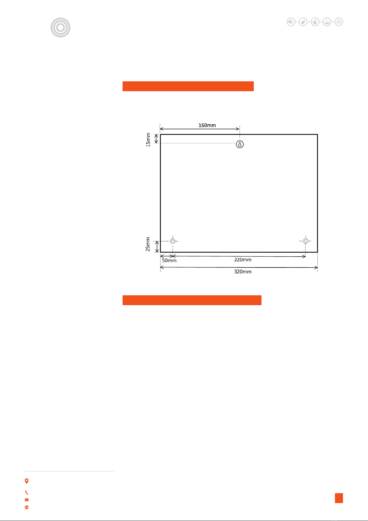
I. SELECT THE MOUNTING POSITION
Choose a location indoors where the panel will be protected from the elements and
temperature extremes.The panel is not suitable for a hazardous location.
Cable splices are often the source of
problems. It is strongly recommended to
splice only cables of the same characteristics
(wire cross section, capacitance, etc). The
splicing contact resistance must be as low
as possible. Twisted wire splicing under a
wire nut or terminal strip can deteriorate
over a certain period of time. It is, therefore,
advisable to use soldering splices. For
shielded cable the shield must be continued,
but it must not be grounded at the splicing
points. Splices need to be water-tight to
prevent the entry of water into the cable,
which could result in increased capacitance.
Note: Bad splices and/or splices left
uncovered, exposed to humid environments,
could create critical problems dicult
to locate. During the installation of each
module, the length of external cables (input/
output) must be selected according to the
J. CABLE SPLICES AND CONNECTIONS
datasheet reference. These wires must be
treated as signal wires and be kept away
from contactors, relays, motors and other
inductive noise sources. In extreme cases it
is necessary to use shielded cable. But here
the shield must also be properly grounded at
one point only. With the high exibility of the
Bus wiring, external input and output wires
should, of course, be kept as short as possible
by bringing the Bus to the points where
signals are to be transmitted or received.
Note: if multi-conductor cable is used, where
some of the conductors are spare, we highly
recommend connecting all spare wires to
ground (preferably close to the main panel).
This to reduce the “antenna eect” of open-
end wires.
Aqui
N
et
AquiNet
Fieldbus Network System
LEAK DETECTION SOLUTIONS
Weights & Measures House, 20 Barttelot Road,
Horsham, West Sussex RH12 1DQ
+44 (0) 1403 216100
www.aquilar.co.uk
5
Do not connect any of the wires to other voltage potentials.
Do not connect any of the wires to protective earth (PE).
Do not parallel any wires to increase the square of the cores.
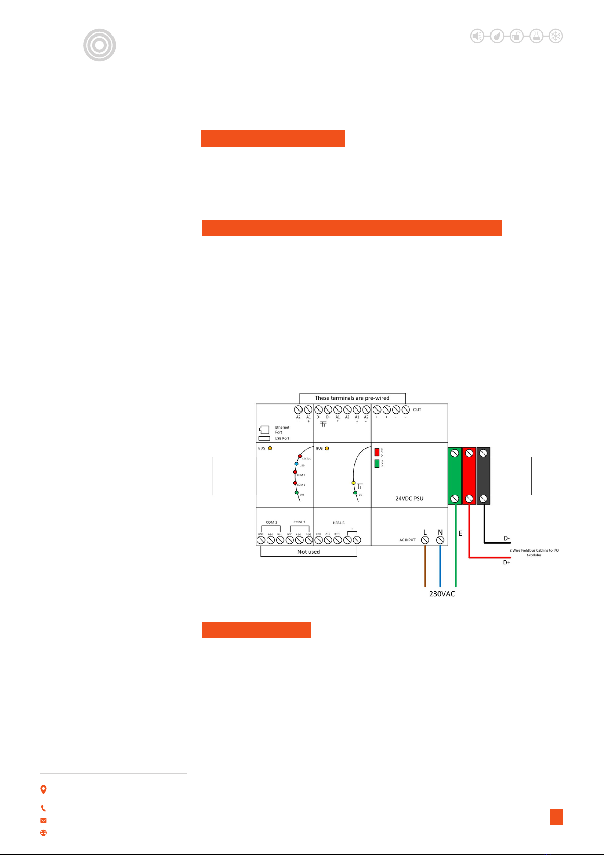
K. RECOMMENDATIONS
•Pass the power cable through the knock-out/adapter/bushing if tted.
• Connect the power supply wires to the terminals as shown in the diagram below.
• The electrical supply should be fused at no more than 3 amps via an un-switched fused spur
adjacent to the panel.
•The 2 wire eldbus network cabling is wired into the D+ and D- terminals as shown in the
diagram below.
The BACNet Gateway and Fieldbus Generator are supplied pre-wired. This cabling should not
be removed or altered in any way.
L. CONNECTING POWER AND FIELDBUS NETWORK
When power is applied, the panel will start-up the pre-installed GUI (graphical user interface)
specific to the project. Providing all ZCM I/O modules are successfully connected and the
system has been commissioned, the panel is now monitoring for leaks.
M. POWERING UP
Aqui
N
et

AquiNet
Fieldbus Network System
LEAK DETECTION SOLUTIONS
Weights & Measures House, 20 Barttelot Road,
Horsham, West Sussex RH12 1DQ
+44 (0) 1403 216100
www.aquilar.co.uk
Aqui
N
et
Once all the modules on the network have been wired and connected to the AquiNet panel, the
SB software tool can be used to discover the modules to check if all the wiring is correct.
N. SB TOOL - MODULE CONFIGURATION
SOFTWARE
• Contact Aquilar for the the latest version of
the SB Tool.
TOOLS REQUIRED
• Laptop runing Windows 7/8/10 and an
ethernet patch lead.
Once installed, launch the program.
The conguration will load and display the list of all modules associated with the Sx2WEB24.
If multiple Sx2WEB24 Controllers are used, ensure you are connected to the correct unit
associated with the conguration le loaded.
CONNECTING TO THE SXWEB24
If using a laptop to connect to the SxWEB24 you may need to conigure your network adaptor to
enable communication. If this is necessary please follow the instructions below.
Disable/turn off wireless. Right click on the LAN icon and select open ‘network and sharing centre’.
Select ‘change adaptor settings’.
6

AquiNet
Fieldbus Network System
LEAK DETECTION SOLUTIONS
Weights & Measures House, 20 Barttelot Road,
Horsham, West Sussex RH12 1DQ
+44 (0) 1403 216100
www.aquilar.co.uk
Aqui
N
et
Your computor may have more than one network connection on this page. Select the one
named ‘Local Area Connection’. Right click it and select properties from the menu.
On the popup screen highlight ‘Internet Protocol Version 4 (TCP/IPv4)’ then click properties.
7

AquiNet
Fieldbus Network System
LEAK DETECTION SOLUTIONS
Weights & Measures House, 20 Barttelot Road,
Horsham, West Sussex RH12 1DQ
+44 (0) 1403 216100
www.aquilar.co.uk
Aqui
N
et
Change the setting from obtain an IP address automatically, to use the following IP address.
Enter an IP in the same range as the Sx2WEB24 gateway, for standard settings we recommend
192.168.1.19. Click ok (the subnet mask will self populate).
Connect a ethernet patch lead from the computer into the ethernet port of the Sx2WEB24
Controller. You may have to remove the yellow ethernet lead connecting the AquiNet
touchscreen to the SxWEB24.
After a power on, the Sx2WEB24 master unit is ready to work after about 1 minute. Only when
the yellow BUS Led starts ashing the master unit is ready.
At the bottom left of the window, type in the IP address of the Sx2WEB24 you are connecting
to. The default for most congurations is 192.168.1.20. Aquilar will provide information if a
dierent conguration is used.
Click connect and if a successful connection is made, the grey circle will turn green and the
status light on the Sx2WEB24 will ash red.
8

AquiNet
Fieldbus Network System
LEAK DETECTION SOLUTIONS
Weights & Measures House, 20 Barttelot Road,
Horsham, West Sussex RH12 1DQ
+44 (0) 1403 216100
www.aquilar.co.uk
Aqui
N
et
This will load the le for your project into the software. In the lower screen you should see a
list of all the modules on your system. If correctly loaded you will see the correct name in the
‘Project name:’ box
9
IMPORTANT
If the PC is running the Windows Firewall or a Third party Firewall / Antivirus, make sure that
the ports 48007, 10000, 10001 are not blocked (input/output packets). These ports are used by
the Sx Tool to search for the master unit in the network and for communication. If a rewall
blocks these ports, the Sx Tool will not be able to nd the controllers in the network or to use
the Live Signals.
Aquilar will provide a conguration le associated with the project. This will contain details of all
the modules on the network and have all the instance numbers pre-congured. This should be
saved to an accessible folder on the machine used to carry out the system programming.
To open the cong le for your project press open. This will open a browser window. Navigate
to the location of your previously saved SB Tool cong le, select it and click open.

AquiNet
Fieldbus Network System
LEAK DETECTION SOLUTIONS
Weights & Measures House, 20 Barttelot Road,
Horsham, West Sussex RH12 1DQ
+44 (0) 1403 216100
www.aquilar.co.uk
Aqui
N
et
Click “Send to controller” from the le menu. (if this button is greyed out then the PC is not
connected to a gateway). This will open the compile manager window,start the network and
send the programme to the sytem via the gateway. Once complete you should see a window as
below with all green ticks and no errors.
If there any errors, check the eldbus dupline wiring for possible cross overs, loose connections
or short circuits.
Once any dupline network wiring issues have been corrected press send to controller again.
Please be aware that by default the software will only congure modules not found on the
previous download attempts.
Ret the yellow ethernet cable linking the touchscreen to the SxWEB24 gateway. The ‘sensor
status’ page on the touch screen should now register all the sensors as ‘OK’ next to the room
and comms for each module. Depending on the size of system this may take several minutes to
complete.
The system will now be monitoring for leaks.
10

AquiNet
Fieldbus Network System
LEAK DETECTION SOLUTIONS
Weights & Measures House, 20 Barttelot Road,
Horsham, West Sussex RH12 1DQ
+44 (0) 1403 216100
www.aquilar.co.uk
Aqui
N
et
CHANGING AN-ZCM ZONE CONTROL MODULES
If an AN-ZCM is changed on site for any reason then the SIN number must also be changed in
the conguration software.
Find the module that has been removed and enter the new modules SIN number.
The new modules SIN number can be found on the side of the module.
Save as a new or overwrite the existing conguration and then send to controller to allow the
system to nd the new module.
11

AquiNet
Fieldbus Network System
LEAK DETECTION SOLUTIONS
Weights & Measures House, 20 Barttelot Road,
Horsham, West Sussex RH12 1DQ
+44 (0) 1403 216100
www.aquilar.co.uk
12
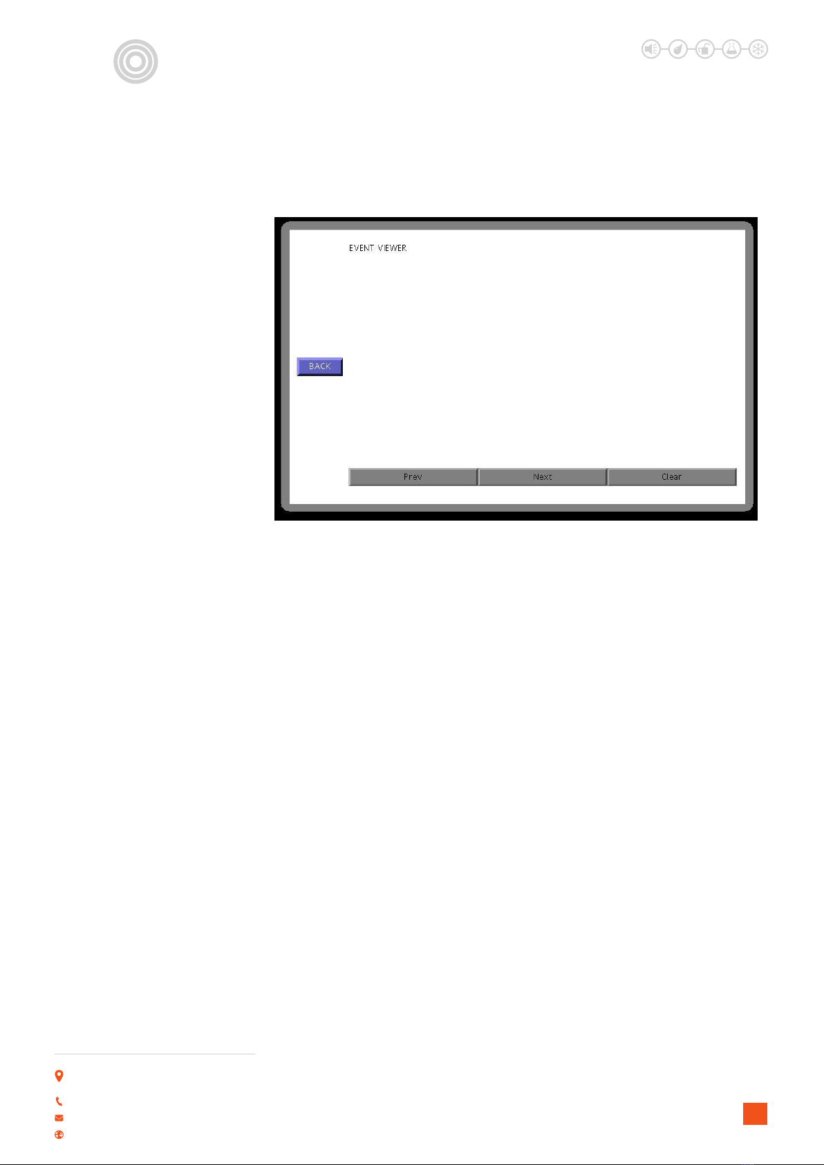
Home screen displays general status and buttons for access to other pages.
Aqui
N
et
The GUI is supplied bespoke for the project containing information relevant only to the project.
An example of the interface as follows –
P. USING THE GRAPHICAL USER INTERFACE
Page showing status of all sensors.
LEAK DETECTION SOLUTIONS
Weights & Measures House, 20 Barttelot Road,
Horsham, West Sussex RH12 1DQ
+44 (0) 1403 216100
www.aquilar.co.uk
13
Important: All information, including illustrations, is believed to be reliable. Users, however,
should independently evaluate the suitability of each product for their application. Aquilar
Limited makes no warranty as to the accuracy or completeness of the information, and
disclaims any liability regarding its use. The only obligations of Aquilar Limited are those in
the Aquilar Standard Terms and Conditions of Sale for this product, and in no case will Aquilar
Limited be liable for any incidental, indirect, or consequential damages arising from the sale,
resale, use or misuse of the product. Specications are subject to change without notice. In
addition, Aquilar Limited reserves the right to make changes – without notication to Buyer
– to processing or materials that do not aect compliance with any applicable specication.
AquiTron is a trademark of AquiTron Limited
Aquilar is a trademark of Aquilar Limited
AquiNet
Fieldbus Network System
Aqui
N
et
08/09/2017 11.46 LEAK DETECTED room 101
V210.2018
Table of contents
Other aquilar Measuring Instrument manuals


Popular Measuring Instrument manuals by other brands


Saturn South
Saturn South SS9007.2 Mini user manual

Simpson
Simpson 897 Operator's manual

PCB Piezotronics
PCB Piezotronics IMI SENSORS Swiveler ICP M607A01 Installation and operating manual

IMV
IMV SmartVibro VM-7024H instruction manual

PST
PST MITCHELL S8000 -100 user manual

Honeywell
Honeywell FS20X Series Quick reference guide