Bayrol NATURALLY SALT Salt Relax POWER Specification sheet

Salt Relax POWER
Version 2.9
EN
Operating and installation manual


Content
Content
1General safety instructions................................................... 3
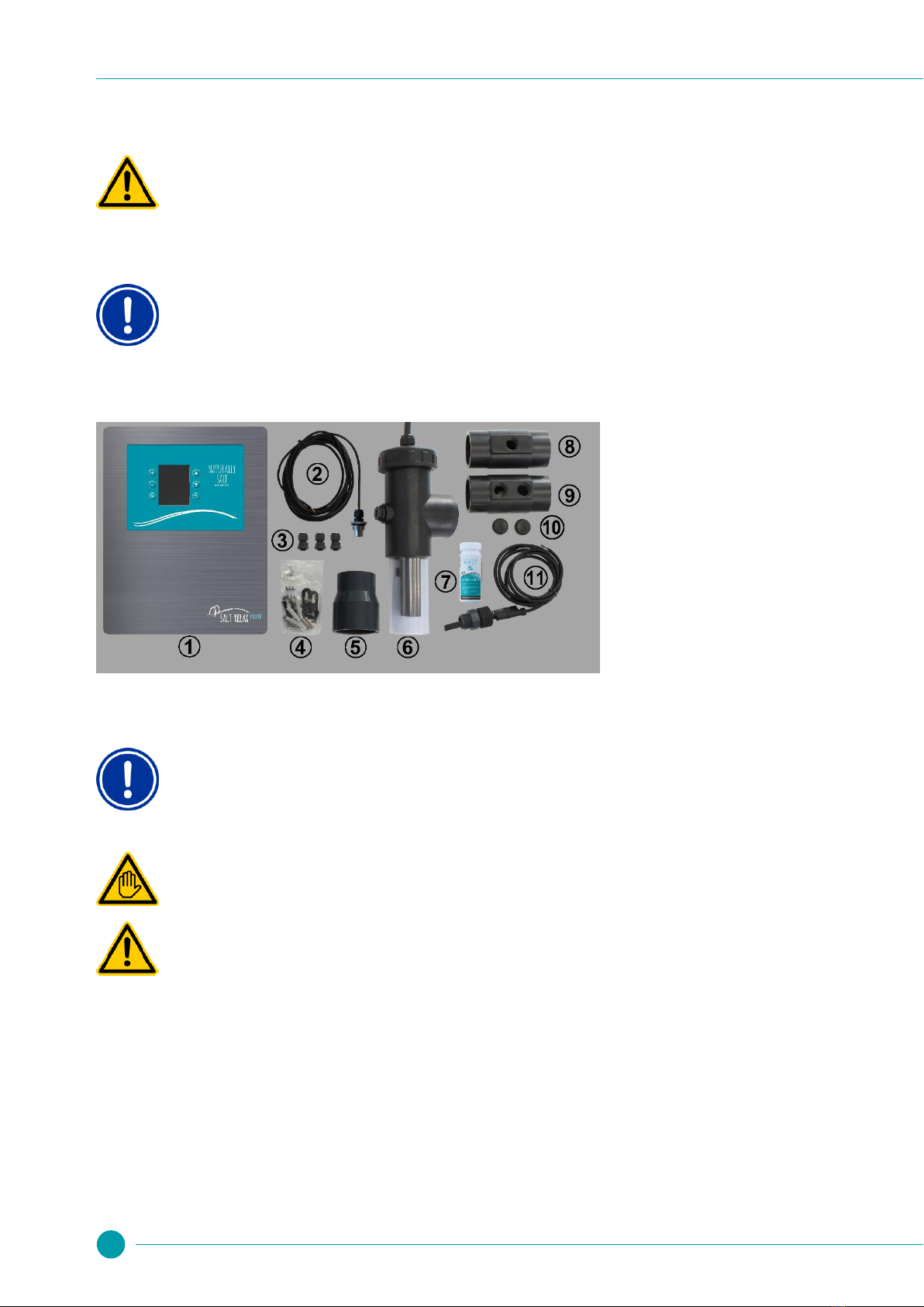
2Content of the packaging...................................................... 4
3Installation .............................................................................. 4
3.1 Wall installation..................................................................... 5
3.2 Electrical connection............................................................. 5
3.2.1 Supply via the filter control.................................................... 5
3.2.2 Salt Relax POWER as filter control ...................................... 6
3.3 Connecting the chlorine production cell................................ 6
3.4 Connecting the temperature sensor ..................................... 6
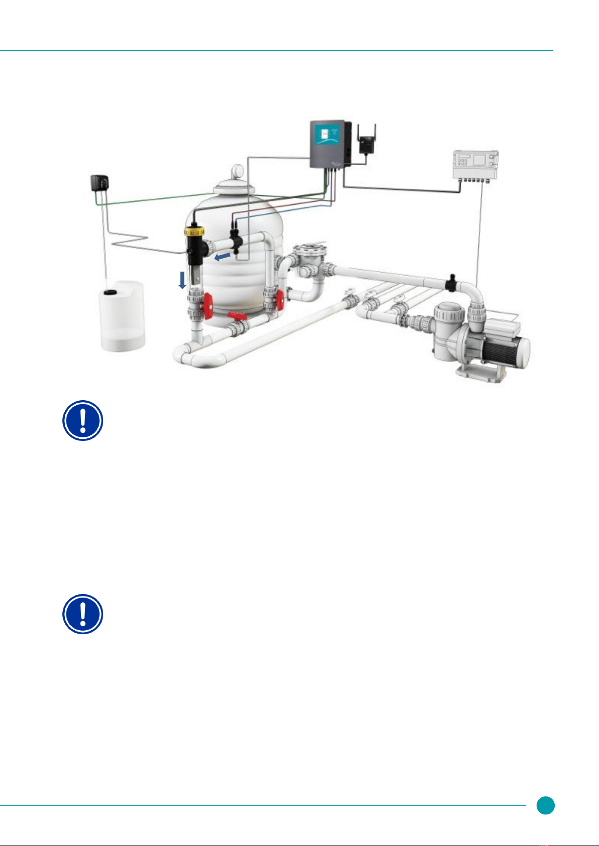
3.5 Installation diagram............................................................... 7
3.6 Installing the additional flow switch....................................... 8
3.7 Earthing................................................................................. 8
3.8 Setting the water................................................................... 8
3.8.1 Water chemistry .................................................................... 8
3.8.2 The right salt ......................................................................... 9
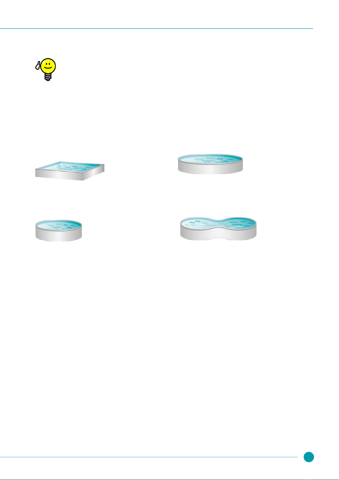
3.8.3 Calculating the pool volume.................................................. 9
3.8.4 Calculating the amount of salt to add ................................... 9
3.9 Adding the salt to the pool .................................................... 9
4Operating the Salt Relax POWER....................................... 10
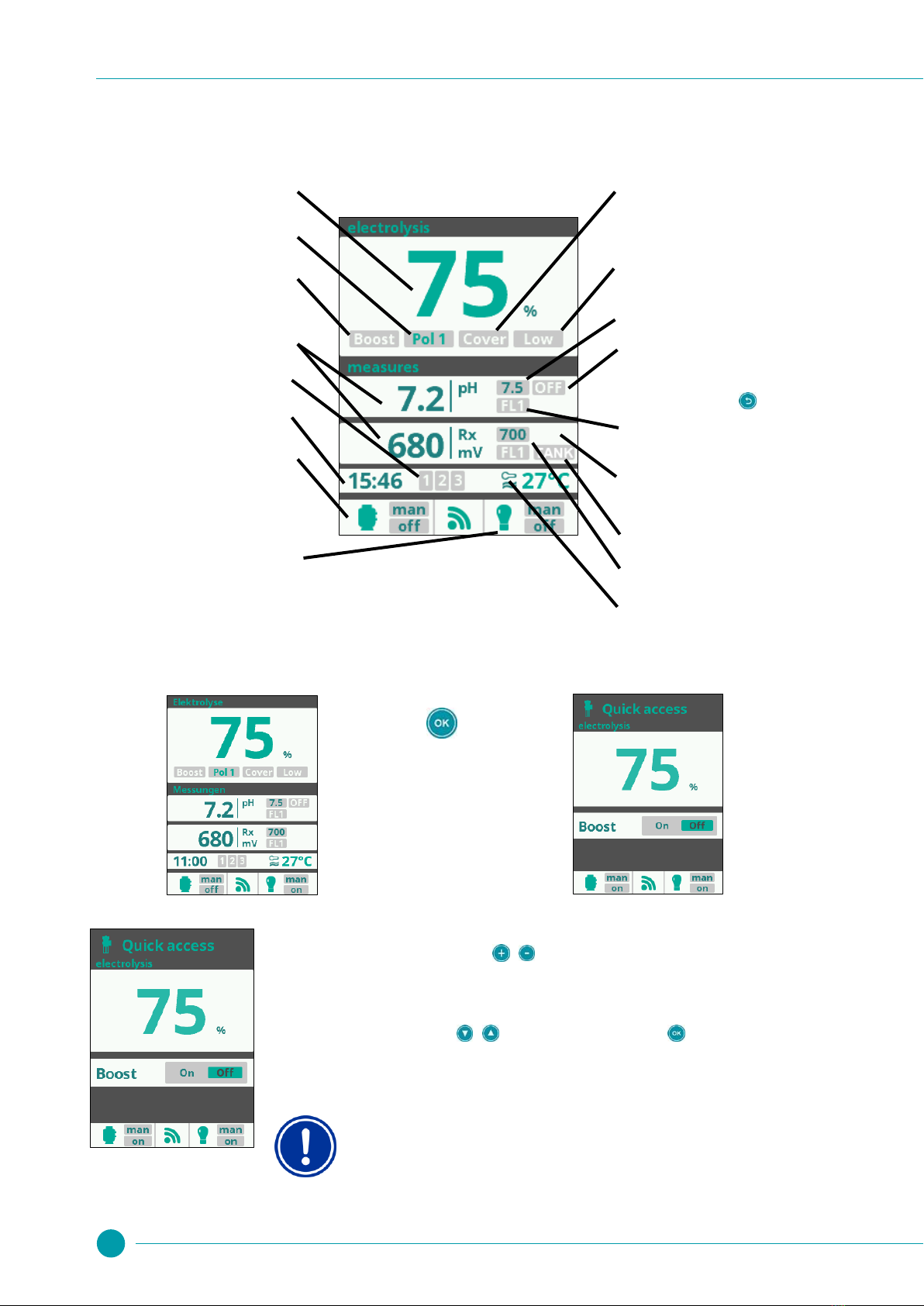
4.1 Main screen ........................................................................ 10
4.2 ............................................................................................ 10
4.2 Quick access to salt electrolysis ......................................... 10
4.3 The main menu ................................................................... 11
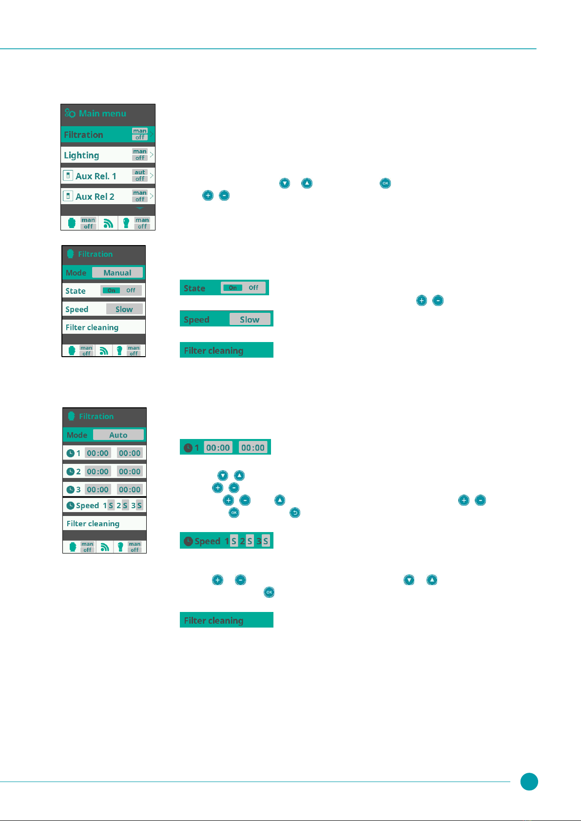
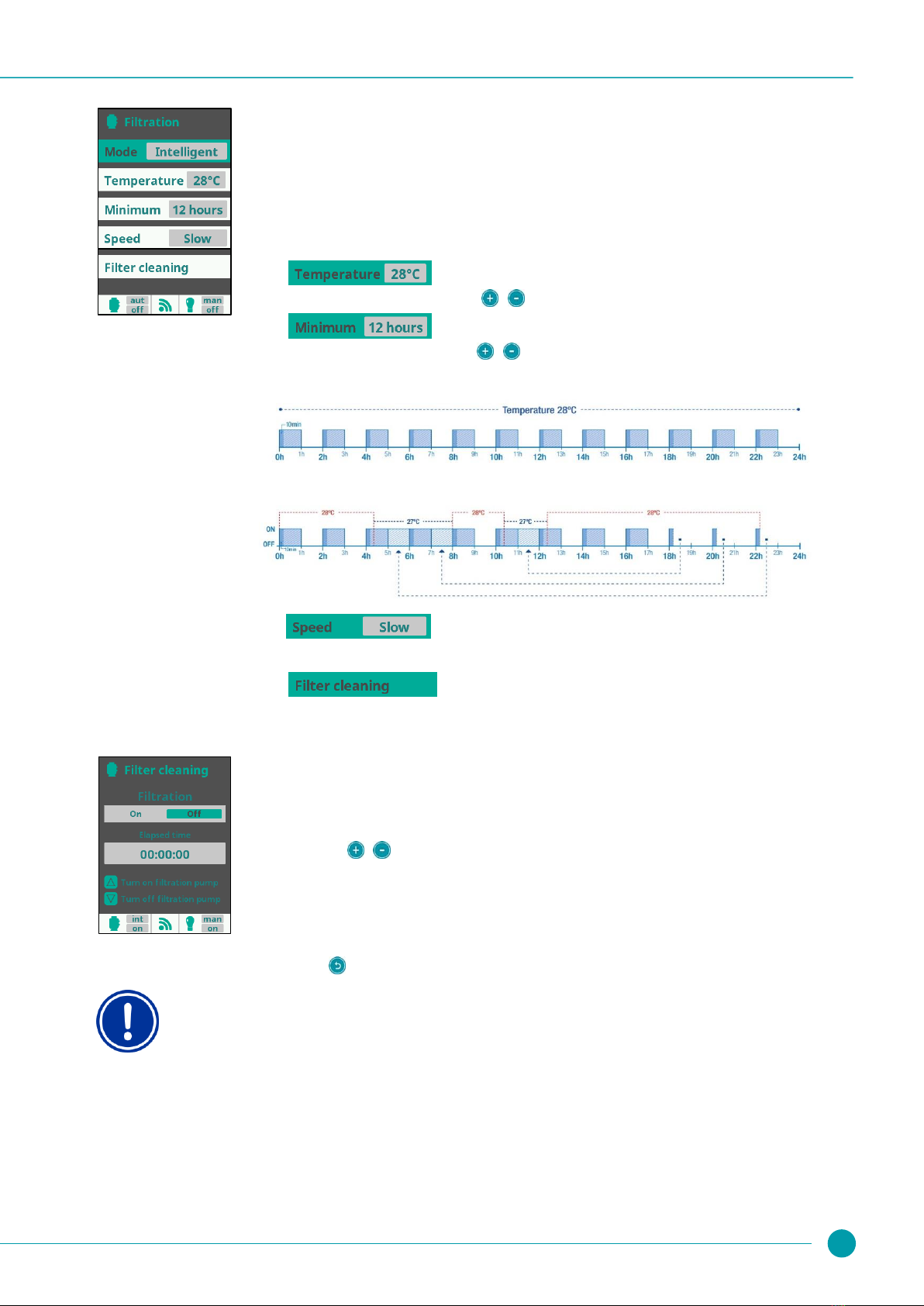
4.3.1 Filtration .............................................................................. 11
4.3.2 Lighting................................................................................ 14
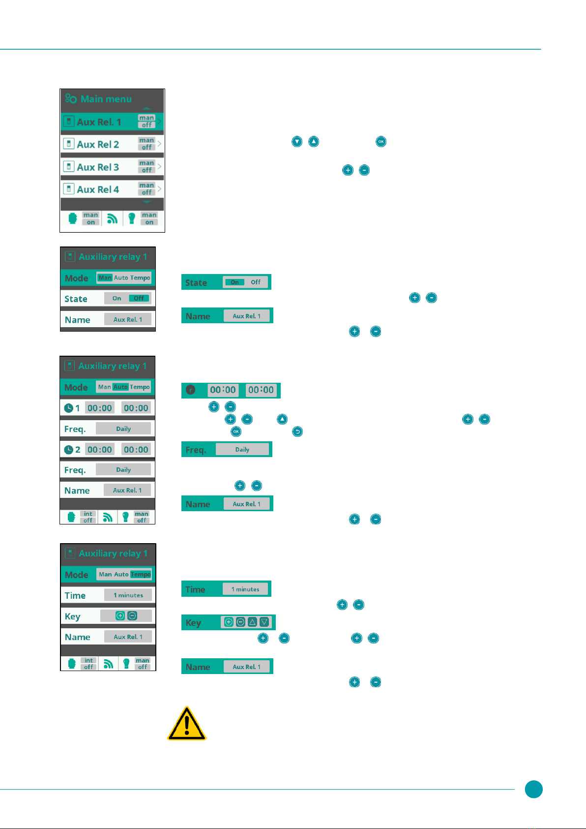
4.3.3 Auxiliary relays (Aux Rel1, Aux Rel2 Aux Rel3, Aux Rel4). 15
4.3.4 pH calibration / redox calibration / setpoint......................... 16
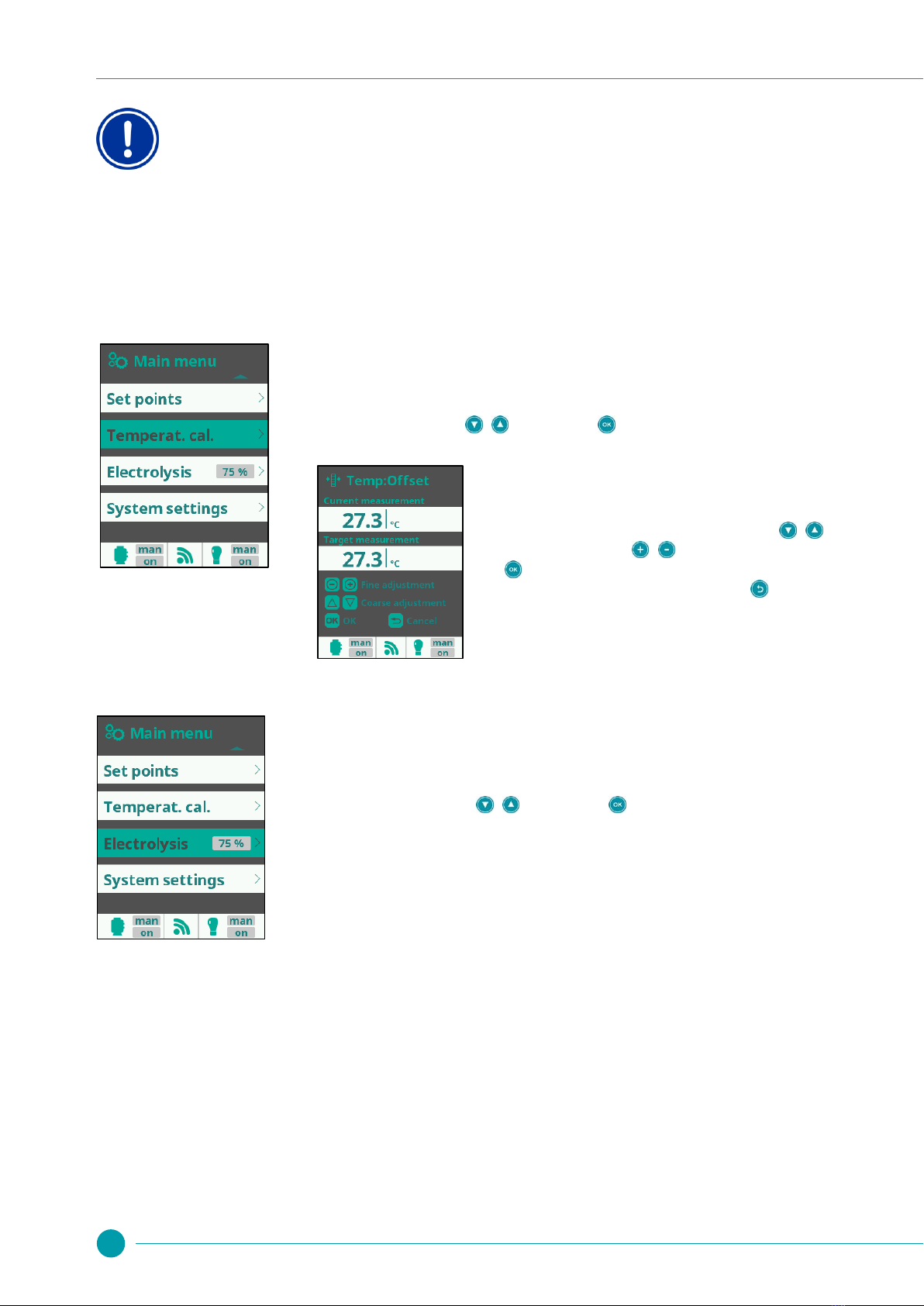
4.3.5 Temperature calibration...................................................... 16
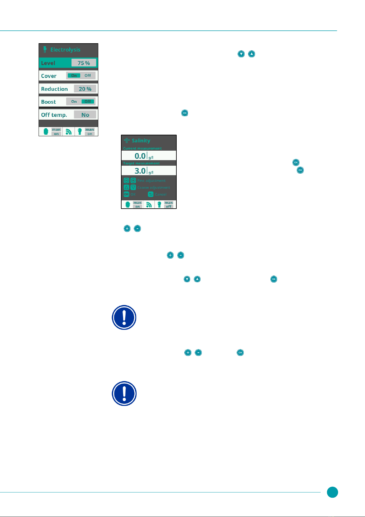
4.3.6 Electrolysis.......................................................................... 16
4.4 Settings menu ..................................................................... 18
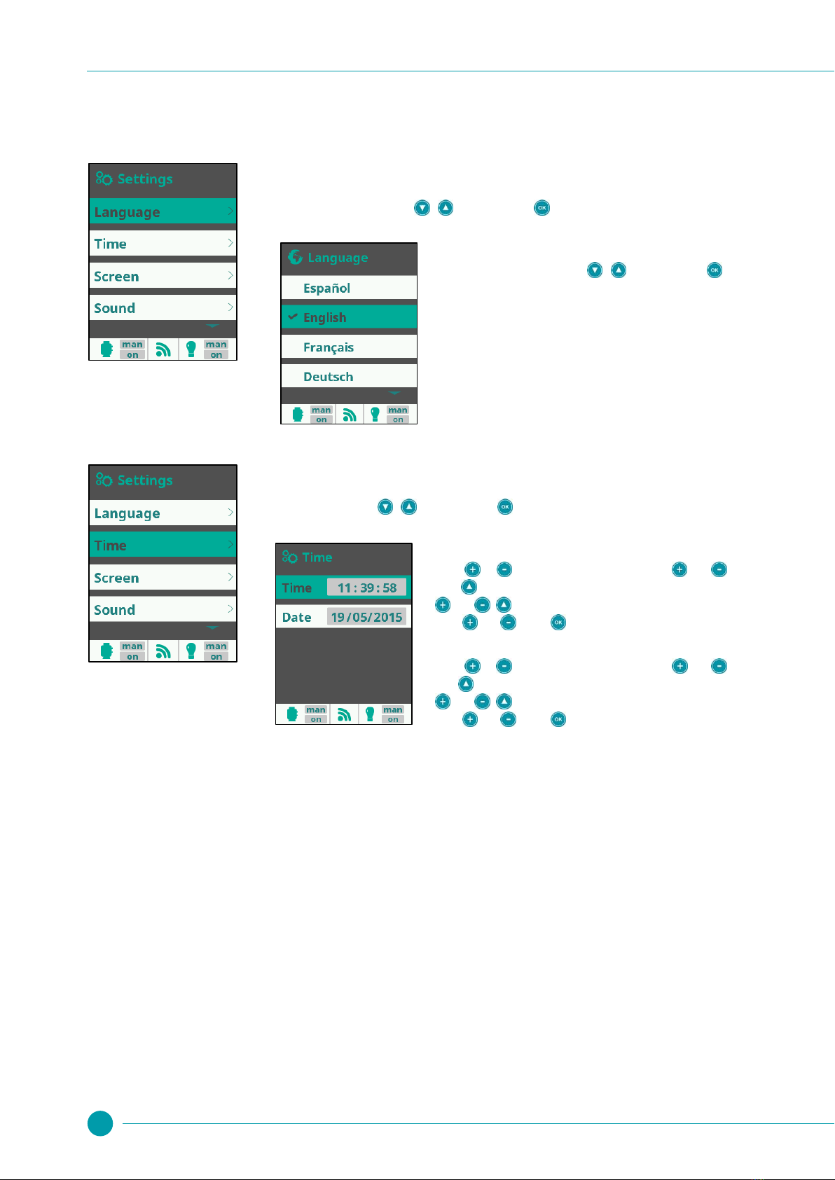
4.4.1 Language ............................................................................ 18
4.4.2 Time .................................................................................... 18
4.4.3 Network............................................................................... 19
4.4.4 Screen................................................................................. 19
4.4.5 Sound.................................................................................. 20
4.4.6 Password ............................................................................ 20
4.4.7 Cell hours............................................................................ 20
4.4.8 System info ......................................................................... 20
4.4.9 Service menu ...................................................................... 20
4.5 Service menu ...................................................................... 21
4.5.1 Relay configuration ............................................................. 21
4.5.2 Service settings................................................................... 23
4.5.3 Pump type........................................................................... 25
4.5.4 Dos. pumps......................................................................... 26
4.5.5 Extra settings ...................................................................... 27
4.5.6 Reset settings......................................................................27
4.5.7 Reset counters.....................................................................27
5pH option ...............................................................................28
5.1 Scope of delivery, pH option................................................28
5.2 Installing the pH module ......................................................28
5.3 Installing the pH electrode ...................................................28
5.4 Installing the pump and injection nozzle..............................28
5.5 Settings on the device .........................................................29
5.5.1 Set point pH.........................................................................29
5.6 Calibrating the pH electrode ................................................30
5.6.1 2-point calibration with the two buffer solutions provided (pH 7
and pH 10)...........................................................................30
5.6.2 1-point pH calibration...........................................................31
6Redox option.........................................................................32
6.1 Scope of delivery, redox option ...........................................32
6.2 Installing the Redox module ................................................32
6.3 Installing the redox electrode...............................................32
6.4 Redox setpoint.....................................................................32
6.4.1 Determining the redox setpoint............................................32
6.4.2 Setting the redox setpoint on the device .............................33
6.4.3 1-point redox calibration ......................................................33
7WIFI option ............................................................................34
7.1 Scope of delivery, WIFI option.............................................34
7.2 Installing the WIFI module ...................................................34
7.3 Positioning the WIFI module................................................34
7.4 Web portal www.naturally-salt-poolaccess.com..................35
8Description of the device .....................................................35
8.1 Connections and fuses on the Salt Relax POWER.............36
8.2 Removing the housing front cover.......................................36
8.3 Replacing the battery...........................................................36
8.4 Installing a cable grommet...................................................37
8.5 Installing the pH and redox module .....................................37
8.6 Connecting terminals...........................................................38
9Troubleshooting and fault elimination ...............................39
10 Maintenance ..........................................................................41
10.1 Cell cleaning ........................................................................41
10.2 General maintenance ..........................................................41
10.3 Cleaning...............................................................................41
10.4 Replacing the dosing pump hose ........................................42
11 Taking out of service for the winter ....................................42
12 Decommissioning.................................................................42
13 Technical Data.......................................................................43
14 EC Declaration of Conformity..............................................44
1General safety instructions
This operating manual contains important information which must be observed during installation, commissioning, operation and servicing. This
operating manual must therefore be read by the installation engineer and the operator of the device prior to installation and commissioning and must
be kept in a location where it is accessible to all users.
Sensitive settings are correspondingly marked, and such settings may only be made by a specialist with both in-depth knowledge of swimming pool
construction and in-depth knowledge of the installation of electrical and electronic devices.
Compliance with all other safety instructions in this document is also mandatory.
Read and follow all instructions.
To minimise the risk of injury, do not allow children to use this product.

2Content of the packaging
4
Failure to follow the safety instructions may result in danger to persons, the environment and the device itself. Failure to observe the safety
instructions will also lead to the forfeiture of claims for damages and loss of warranty.
The Salt Relax POWER is intended exclusively for use in private swimming pools.
DANGER!
Danger resulting from inadequate qualification of personnel/service technicians/installation technicians. Possible consequences are
serious or even fatal injury and severe damage to material assets. The following conditions therefore apply:
The operator of the plant must ensure that personnel are adequately qualified.
All tasks must be performed exclusively by correspondingly trained personnel.
The system must be protected against access by persons who are not adequately qualified, e.g. by means of access codes and
passwords.
IMPORTANT!
The operator of the plant must ensure compliance with the relevant accident prevention regulations, other legal provisions and the
generally accepted rules of safety engineering!
2Content of the packaging
1 Salt Relax POWER
2 Temperature sensor
3 Cable grommets
4 Installation material
5 Reducer 75-50 mm
6 Chlorine production cell
(cell and housing)
7 Salt Quicktest
8 Holder for temperature sensor
9 Holder for paddle switch and
pH/redox electrodes (optional)
10 Plugs
11 Paddle switch
3Installation
NOTE!
Ensure that all components of the pool system which may come into contact with the pool water are resistant to salt water.
In particular, make sure that the filtration pump is resistant to salt water.
Note that even water with a low salt content can be corrosive, and take this into account when selecting components for use
(e.g. steel ladders etc.).
Necessary qualification:
The Salt Relax POWER must be installed by a specialist with both in-depth knowledge of swimming pool construction and in-depth
knowledge of the installation of electrical and electronic devices!
Danger caused by electrical current
The Salt Relax POWER is live as soon as voltage is applied to the power input. The chlorine production cell or additional functions
may be switched on or switched over. Contact with live components can lead to an electric shock.
This may result in serious or even fatal injury and damage to material assets, and the following therefore apply:
All such tasks must be carried out exclusively by adequately trained and experienced personnel!
The device must always be de-energised before performing installation and maintenance work on it!
Secure the device against being switched on while work is being performed on it!
Additional modules must be installed/removed in de-energised state!
Cables must also be connected in de-energised state!
A safety feature which is independent of the device should always be present!
Where necessary, password protection for the main menu must be activated!
The relevant country-specific safety regulations must be complied with!
All safety features and protective devices must be refitted or rendered functional again immediately after completing work!
Failure to follow the safety instructions can cause the device to malfunction, may lead to the risk of fatal injury and renders the
warranty invalid!

3Installation
5
3.1 Wall installation
Notes on installation:
The device must be mounted on a flat, vertical surface protected against moisture.
There must be adequate free space around the device to allow correct operation and maintenance of the device.
It must be possible to remove the front cover of the device.
A space of at least 20 cm below and to the side of the device is required for routing cables.
A wet room Schuko socket (two pin earthed plug) with continuous current is required at a distance of not more than 1.5 m.
All cables must be routed without kinks and chafing points.
Avoid exposure to direct sunlight, heat radiation, frost and moisture. Ensure adequate ventilation.
No live cables, contactors, electric motors etc. in the immediate vicinity.
The installation location should be as close as possible to that of the chlorine production cell (note cable length).
The Salt Relax POWER with the mounted holders can be used as a template for drilling by holding it up against the mounting location and
marking the position of the drill holes on the wall.
3.2 Electrical connection
The Salt Relax POWER has been designed and constructed according to the applicable regulations. It was carefully inspected before leaving the
factory and left the factory in a safe and technically flawless condition.
The equipment can only be operated safely if all of the instructions contained in this manual are followed.
The supply voltage for the device must not exceed 110 - 240V/60 Hz. The permissible operating temperature range is from 0 to 50 OC, the permissible
humidity level 0-90 %.
As is standard practice for electrical connections, ensure that all plug-in connections and cable grommets are protected against water.
3.2.1 Supply via the filter control
If the Salt Relax POWER is activated via an external timer (e.g. filter control), it must be ensured that the circulating pump and the Salt Relax POWER
are precisely synchronised. The Salt Relax POWER must be switched off if there is no flow of water.
Make sure that the external timer (e.g. filter control) meets the performance requirements of the Salt Relax POWER!

3Installation
6
In order to supply the Salt Relax POWER with power via a filter control as shown in the diagram above, the mains power plug supplied can be
dismantled as shown below.
Attention:
Connection of the Salt Relax POWER in this way must be performed by a specialist technician with in-depth knowledge of the
installation of electrical and electronic devices!
When connecting the power supply cable of the Salt Relax POWER to the filter control, it is imperative to follow the instructions
(connection diagram) provided with the filter control.
3.2.2 Salt Relax POWER as filter control
As standard, the Salt Relax POWER can be used as a controller for the filtration pump; please refer to the section Filtration. In this case, the mains
power plug of the device is connected to a water-protected mains socket with a 30 mA residual current circuit breaker.
See also the information in the chapters Filtration, Configuration and Connecting terminals.
3.3 Connecting the chlorine production cell
When connecting the cell supply cable to the control unit, make sure that the cable is inserted firmly at the points provided, with no loose contact. The
cap nut of the plug-in connection must be securely tightened. If this is not the case, there is a risk of overheating at this connection.
Also insert the second, thinner cable (gas flow sensor) of the chlorine production cell carefully into the connection point provided (see Connections
and fuses on the Salt Relax POWER).
3.4 Connecting the temperature sensor
The temperature sensor cable is routed into the Salt Relax POWER through the cable grommet mounted at the factory on the underside of the
housing front cover (see "Installing a cable grommet") and connected as described.

3Installation
7
3.5 Installation diagram
The illustration shows connection of the Salt Relax POWER via the filter control.
The holder for electrodes and temperature sensor can also be attached directly inside the chlorine production cell with adhesive.
NOTE
We recommend that the cell is always installed in the bypass. Installation in this way is mandatory if the flow rate exceeds 15 m3/hour,
in order to avoid load losses. Installation in the bypass makes it much easier to carry out maintenance on the chlorine production cell
and the optionally installed sensors.
If you install the cell in the bypass, you should fit a non-return valve in the bypass line after the cell in place of a manual valve, in order
to rule out the danger of accidental actuation.
It is imperative to note that the chlorine production cell must always be the last element installed on the return line to the pool (see sketch above).
To enable use of the integrated gas flow sensor, the cell must be positioned vertically. The sensor will only function correctly if this is the case. If
installation in vertical position is not possible, the paddle flow switch supplied with the device must be used!
Please note that the water flows through the chlorine production cell as shown in the diagram and not in the reverse direction.
The chlorine production cell itself is attached inside the bypass piping with adhesive. Depending on the diameter of the pipe, it may be necessary to
use the reducer supplied.
NOTE
When inserting the cell into the cell holder, make sure that the cell blades are positioned in the direction of flow of the water. This
ensures that the blades offer the lowest possible resistance to the water flowing through the cell.

3Installation
8
3.6 Installing the additional flow switch
It must be ensured that the chlorine production cell is only in operation when pool water is flowing through it.
The Salt Relax POWER is equipped with a gas flow sensor integrated in the chlorine production cell. This sensor only functions if the cell is installed in
vertical position. If, for technical reasons, it is not possible to install the cell vertically, or if a double dosing lock is to be used, the paddle flow switch
provided can be installed; see installation diagram above.
This paddle sensor must be installed directly in front of the chlorine production cell. The electrode holder supplied has a drilled hole for the paddle
switch on its underside and is used as the holder for the paddle switch. Ensure that the holder is mounted in the bypass line in front of the cell.
NOTE
When installing the paddle flow switch, it is essential to ensure that the arrow printed on the switch matches the direction of flow of the
water!
Connecting the paddle flow switch in the Salt Relax POWER
An additional cable grommet must be created in order to connect the paddle flow switch inside the device. To do this, follow the instructions in
"Installing a cable grommet."
3.7 Earthing
Note that even water with a low salt content can be corrosive. To minimise the corrosive effect, BAYROL recommends the installation of a "sacrificial
electrode" in the pumping system of the pool. Ask your specialist swimming pool dealer for details.
NOTE
When selecting components (e.g. steel ladders etc.), always take into account that corrosion may occur. It is essential to select
components which are suitable for use with salt water. BAYROL expressly refuses to accept liability for damage caused by corrosion!
3.8 Setting the water
3.8.1 Water chemistry
The table below lists the recommended main water values:
Salt content (g/l)
pH value (pH)
Free chlorine content
(mg/l or ppm)
Alkalinity/TAC
(ppm)
Total hardness/TH
(ppm)
Stabiliser/
isocyanuric acid
(ppm)
Permissible
values
1.5 - 100 g/l
7.0 - 7.5
0.5 - 2
80 - 120
100 - 500
(5.6 - 28 odH)
25 - 60
Recommended
values
1.5 –3.0
7.2
0.6 - 1.2
90 - 110
100 - 300
approx. 30
To increase
Add salt
Add
pH-Plus
Increase output of the cell;
trigger Boost function;
add chlorine manually
Add Alca-Plus
Add calcium chloride
Add cyanuric acid
To reduce
Partly drain pool and
refill
Add
pH-Minus
Decrease output of the
cell
Add pH-Minus
Use a water softening
plant
Partly drain pool and
refill
Test during
the bathing
season
after backwashing
(after refilling the
pool)
weekly
weekly
monthly
monthly
monthly
When filling your pool from scratch, it should be noted that initial adjustment of the water can take some time. You may need to add water care
products (e.g. pH-Minus) several times within the first 1 - 2 weeks.
Please consult your specialist swimming pool dealer if you are uncertain about the adjustment of the water quality in your pool.

3Installation
9
Please ensure that the values given in the table are complied with beyond the end of the bathing season by regularly testing and if necessary
correcting the water quality. The required test sets and the respective water care products are available from your specialist BAYROL swimming pool
dealer.
TIP
Check the cyanuric acid content when you check the salt content. These two values usually drop at the same time.
3.8.2 The right salt
Use only salt intended for use in swimming pools with salt electrolysis systems. Such salt has a high level of purity and is usually sold by specialist
swimming pool dealers in 25 kg sacks.
Never use rock salts, de-icing salts, salts with sodium ferrocyanide, salts with separating agents or iodised salts!
The Salt Relax POWER is suitable for operation with sea water.
3.8.3 Calculating the pool volume
Rectangular pools Oval pools
Length (m) x width (m) x depth* (m) = pool volume (m3) Longest length (m) x greatest width (m) x depth* (m) x 0.89 = pool volume (m3)
Round pools Figure-8 pools
Diameter (m) x diameter (m) x depth* (m) x 0.79 = pool volume (m3)Longest length (m) x greatest width (m) x depth* (m) x 0.85 = pool volume (m3)
*Depth = average depth of the water
3.8.4 Calculating the amount of salt to add
The amount of salt to be added to a freshly filled pool (salt-free water) is calculated with the following formula:
Desired salt content (g/l) x pool volume (m3) = amount of salt to be added (kg)
The amount to be added to water which already contains salt is calculated with the following formula:
[Desired salt content (g/l) –existing salt content (g/l)] x pool volume (m3) = amount of salt to be added (kg)
3.9 Adding the salt to the pool
Before adding the salt:
Check that the pH value of the water is within the optimum range (pH 7 to pH 7.4).
Also check that the water in the pool is free from metals and of perfect quality. If necessary, carry out shock chlorination of the water. It is best to do
this when the water is at a temperature of at least 20OC.
Adding the salt:
Switch the circulating pump on and open all inlets and outlets to ensure the greatest possible flow of water through the pool. If fitted, also activate the
bottom drain. Pour the salt directly into the pool. Do this at a point where there is high flow, e.g. at the inlet jets. Ideally, swirl the salt around with a
long-handled broom to accelerate the dissolving process. After adding the salt, run a filtration process continuously for at least 24 hours to ensure that
the salt is fully dissolved and evenly distributed.

4Operating the Salt Relax POWER
10
4Operating the Salt Relax POWER
4.1 Main screen
4.2
4.2 Quick access to salt electrolysis
The Quick Access function allows rapid activation of the Boost function and easy adjustment of the output of the chlorine production cell.
Electrolysis output
Set the output (large flashing % value) with / keys of your Salt Relax POWER. Adjust the system
output to suit the requirements of your pool.
This setting corresponds to the setting in the Electrolysis menu.
Boost
Activate the Boost function by using / to select On and confirming with .
The Boost function increases chlorine production to the maximum value (100%) for the following 24 hours of
filtration time, after which it automatically returns to the programmed filtration cycle. In most cases, this is
sufficient to bridge times of increased chlorine requirement. If Salt Relax Pro is controlled via the external
timer, please ensure that the timer runs continuously for 24 hours.
Note
If your pool needs a chlorine shock, we recommend that you administer it by adding chlorine
manually.
Electrolysis
Production intensity in %
Pol 1 Polarity 1
Pol 2 Polarity 2
Boost function
Measured value
pH / redox (optional)
Status of auxiliary relay
Current time
Status of filtration relay
man Manual
aut Automatic
hea Heating
smt Smart
int Intelligent
Status of lighting
man Manual/ aut Automatic
Cover Production automatically reduced
to %age
Low Missing salt / cell encrusted / cell
spent (see Troubleshooting)
Flow Filtration/production stopped due to
lack of water flow
7.2 pH setpoint
ON/OFF Function settings for the
pH-Minus/pH-Plus pump
AL3 Maximum dosing time exceeded (to
reset the alarm, press for 5 sec.)
FL1 Flow signal
ON/OFF Function of the additional
chlorine pump (optional)
Tank signal
700 Redox setpoint (minimum value)
Heating ON/OFF
Hold key pressed for
at least 3seconds.

4Operating the Salt Relax POWER
11
4.3 The main menu
4.3.1 Filtration
The Filtration menu allows you to set the activation of the filter pump. In addition, depending on the menu item,
control of the heating can also be included.
The line Filtration shows the selected operating mode (man, aut, hea, smt, int) and the current operating state of
the filtration pump (on/off).
To set, select Filtration using / and confirm with . The mode is selected in the line Mode
using the / keys
Manual mode
Allows you to switch the filtration process on and off manually, without timer or additional functions.
Displays whether the filtration pump is switched on. Switch using the keys /
Sets the speed of the circulating pump (only when using a circulating pump with variable speed control).
see below
Automatic mode (time-controlled)
In this mode, filtration can be activated via timers allowing you to enter starting and stopping times. The
timers run on a daily schedule.
Setting the daily switch-on and switch-off times (up to 3 filtration cycles possible).
To set, use / to select the line for the timer you wish to set (1-3).
Press the / keys to access the hour for starting the selected timer. Set the hour at which the timer is
to start using / . Press to enter the minutes of the starting time and set using / . Confirm
your entry with or reject it with .
Set the switch-off time for the selected timer in the same way.
Sets the speed of the circulating pump in the respective filter periods (only when using a circulating pump
with variable speed control).
Press the or keys to access and also change the setting. Use or to switch between 1, 2 and
3. Confirm your entry with .
The speed of the pump is set to slow with S, medium with M and fast with F.
see below
BILD
Filtration
Heating mode

4Operating the Salt Relax POWER
12
Heating mode (via timer with optional climate control)
This mode functions like Automatic mode but in addition offers the option of regulating the temperature.
Set desired temperature with / . There is a hysteresis of 1°C (e.g. desired temperature is 23°C - the
system switches on the heating when the temperature falls below 22°C and switches it off as soon as a
temperature of 23°C is reached).
ON: The filtration pump remains switched on even after the end of a filtration cycle if the measured water
temperature is below the desired temperature. When the desired temperature is reached, filtration and
heating stop until the next programmed filtration cycle.
OFF: The heating runs during the set filtration cycles only.
To set the daily switch-on and switch-off times (up to 3 filtration cycles possible), see Automatic mode.
Sets the speed of the circulating pump in the respective filter periods (only when using a circulating pump
with variable speed control).
Press the or keys to access and also change the setting. Use or to switch between 1, 2 and
3. Confirm your entry with .
The speed of the pump is set to slow with S, medium with M and fast with F.
see below
Smart mode
This mode is based on Automatic mode. In addition, the filtration times are adjusted in accordance with the
temperature. 2 temperatures are entered to do this:
If the temperature falls below this temperature setting, the filtration time is reduced to 5 min/hour.
Above the set temperature, filtration runs at the set times.
Between these two temperatures, the filtration times increase in a linear progression.
Set the temperatures using / .
If Antifreeze mode is activated, the filtration pump is switched to continuous operation as soon as the water
temperature falls below 2°C.
Activate/deactivate frost protection with /
To set the daily switch-on and switch-off times (up to 3 filtration cycles possible), see Automatic mode.
Sets the speed of the circulating pump in the respective filter periods (only when using a circulating pump
with variable speed control).
see below

4Operating the Salt Relax POWER
13
Intelligent mode
This mode uses the two operating parameters desired water temperature and min. filtration time per day
(min. 2 hours to max. 24 hours). Filtration is activated for at least 10 minutes every two hours in order to
check the water temperature.
The selected minimum filtration time is split up so that spread over the day, filtration is switched on and off
for equal amounts of time. If the desired temperature is not reached within one switch-on time, this switch-on
time is automatically extended. The extra time is subtracted from the following filtration cycles, whereby the
first 10 minutes of each filtration cycle are run in every case.
Desired water temperature. Set using /
Minimum filtration runtime. Set using / .
Using the settings (see left) as an example, the diagram below illustrates how this function works:
Sets the speed of the circulating pump (only when using a circulating pump with variable speed control).
see below
Filter cleaning (available in all operating modes)
This menu is used to facilitate backwashing of the sand filter.
As soon as the menu is activated in one of the filtration modes (Manual, Automatic, Heating, Smart,
Intelligent), the chlorine production cell is switched off.
Now proceed as follows:
- Using the / keys, set the filtration pump to Off
- Set the valve of your filtration pump to Backwashing.
- Switch the filtration pump back on again (On). You can follow the expired backwashing time on the counter.
It is imperative to ensure that your filter is adequately backwashed!
- After an appropriate backwashing cycle, switch the filtration pump off and reset the valve to Filtration. If
desired, you can now run a rinse cycle. The process is the same as for backwashing, but the valve is set to
Rinse.
- When is pressed to exit Filter Cleaning, the system switches back to the programmed mode.
NOTE!
BAYROL recommends that you select the maximum filtration times. Long filtration runtimes ensure high filtering performance of the
sand filter and allow adequate production of the disinfection agent.
If filtration runtimes are too short, this will inevitably cause problems with the disinfection of the water (e.g. algae growth etc.)

4Operating the Salt Relax POWER
14
4.3.2 Lighting
With the Salt Relax POWER, you can switch lighting (e.g. underwater lighting or hall lighting) on and off directly or
via a timer.
The line Lighting shows the selected operating mode (manual or auto) and the current operating state of the
filtration pump (on/off).
To set, select Lighting with / and confirm with
The mode is selected in the line Mode using the / keys.
Manual
Allows you to switch the lighting on and off manually.
Shows whether the lighting is switched on. Switch using the keys /
Allows switching to the next light mode in sequence when using a suitable LED light control.
Next colour
Confirm by pressing to manually activate the next colour on the connected
LED control.
Switching interval
Select the interval here in seconds at which the colours programmed on the
connected LED control automatically follow in sequence.
Automatic (time-controlled)
Switch-on and switch-off times for the lighting are defined.
Use the / keys to access the hour for starting the selected timer. Set the hour at which the timer is to
start / . Press to enter the minutes of the starting time and set using / . Confirm your entry
with or reject it with .
The timer can also be set to switch at certain intervals (daily; every 2 days; every 3 days; every 4 days; every
5 days; weekly; every 2 weeks; every 3 weeks; every 4 weeks). Select the desired switching frequency using
/ .

4Operating the Salt Relax POWER
15
4.3.3 Auxiliary relays (Aux Rel1, Aux Rel2 Aux Rel3, Aux Rel4)
With the Salt Relax POWER, you can control up to 4 additional functions (e.g. for water attractions, counter-
current systems, garden lighting etc.). These functions are connected to the up to 4 auxiliary relays.
The following description of auxiliary relay 1 applies analogously to all further relays.
To set, select Aux Rel 1…4 with / and confirm with
The mode is selected in the line Mode using the / keys.
Manual
Allows you to switch auxiliary relay Aux1 on and off manually.
Shows whether relay Aux1 is switched on or off. Switch using the keys /
Allows any name to be selected for relay Aux1. Use or to open the input field.
Automatic (time-controlled)
Up to 2 switch-on and switch-off times are defined for relay Aux1.
Use the / keys to access the hour for starting the selected timer. Set the hour at which the timer is
to start using / . Press to enter the minutes of the starting time and set using / . Confirm
your entry with or reject it with .
The timer can also be set to switch at certain intervals (daily; every 2 days; every 3 days; every 4 days;
every 5 days; weekly; every 2 weeks; every 3 weeks; every 4 weeks). Select the desired switching
frequency using / .
Allows any name to be selected for relay Aux1. Use or to open the input field.
Temporary
When a programmable key is pressed, relay Aux1 is switched on for a defined duration (a typical use, for
example, is to activate the air jets in spas).
Runtime in minutes and a key are defined using / .
The key to be pressed ( or .) is selected using / . Every time this key is pressed during
normal operation, the external device connected to the relay is switched on for the defined time.
Allows any name to be selected for relay Aux1. Use or to open the input field.
ATTENTION
The connected device will also be switched on if the programmed key is pressed by accident.
Only use this function to connect devices which do not give rise to a safety risk!
The switching of the relay is not monitored by any safety feature (e.g. flow switch)!

4Operating the Salt Relax POWER
16
NOTE!
Please note that the respective auxiliary relays can only be used if this is enabled in the Service menu!
Unless enabled, the respective relay is classified as used for other purposes (through predefined functions) and the associated menu
items are not displayed in the main menu.
Aux Rel 3 is generally not used for other purposes and is therefore always visible and utilisable.
4.3.4 pH calibration / redox calibration / setpoint
These menu items are only visible and active if the option pH option and/or the redox option is installed.
Please refer to the chapter pH option and/or Redox option for further information.
4.3.5 Temperature calibration
In this menu, the temperature sensor can be calibrated with the displayed temperature value.
If you control your pool heating with the Salt Relax POWER, this calibrated temperature value is used to switch
the heating on and off.
To set, select Temperat. cal. with / and confirm with
Manual temperature calibration
Specify the temperature at the temperature sensor (e.g. pool water
temperature).
Set this temperature in the line Target measurement using /
(Coarse adjustment) or using / (Fine adjustment), and confirm
with .
If you do not wish to calibrate the temperature, press to exit this menu
item.
4.3.6 Electrolysis
The menu Electrolysis is used to make all settings relating to chlorine production.
The Electrolysis bar displays the set production capacity in %.
To set, select Electrolysis 50% with / and confirm with

4Operating the Salt Relax POWER
17
Output (Level)
Set the output of the chlorine production cell to 0 –100% using / . Adjust the production capacity
of the system to suit the requirements of your pool.
This setting corresponds to the setting in the menu Quick access.
Salinity
The current salinity is displayed here. This display should be regarded as a good indication rather than an
exact measured value. In case of doubt, the salinity should always be established by testing a water
sample and the display then calibrated.
If the Salinity line is confirmed with , a message is displayed indicating the internal measurement of
the cell status. Once this internal measurement is concluded, the display can be calibrated if required.
Calibrating the salinity display:
The current measured value and the required (actual value
established by testing a water sample) value are displayed. To
perform the calibration, enter the value established by testing a
water sample as the required value and confirm with .
If calibration is not required, simply exit the page using without
making any entry.
Cover
Using / , select whether you wish to reduce the production capacity with the pool cover closed.
The precondition for use of this function is a closing signal when the cover is closed. It is connected as
described in the chapter Connecting terminals.
When this function is activated, you can set the option of reducing production if the cover is closed. The
%age value adjustable with / is based on the set production capacity.
Boost function
Activate the Boost function by using / to select "On" and confirming with .
The Boost function increases chlorine production to the maximum value (100%) for 24 hours, after which
it automatically returns to the programmed filtration cycle. In most cases, this is sufficient to bridge times
of increased chlorine requirement.
Note
If your pool needs a chlorine shock, we recommend that you administer it by adding
chlorine manually.
Switch-off temperature
Here, select the water temperature (5 –15°C) below which chlorine production is no longer switched on.
Set the switch-off temperature using / and confirm with
If you wish to activate chlorine production when the water is cold, you can deactivate the temperature limit
with "No."
Note:
Cold water requires little or no disinfection agent. It may therefore be practical to define a
temperature limit here.
Settings
Please refer to the next chapter

4Operating the Salt Relax POWER
18
4.4 Settings menu
4.4.1 Language
Set the desired menu language.
To set, select the language with / and confirm with
Language
Select the desired language with / and confirm with
4.4.2 Time
Setting for the system time.
To set, select Time with / and confirm with
Time
Press or to activate entry of the time. Use and to set the
hour. opens the input window for the minutes, which you can set using
and . opens the input window for seconds, which you can set
using and . Press to confirm the entered time.
Date
Press or to activate entry of the date. Use and to set the
day. opens the input window for the month, which you can set using
and . opens the input window for the year, which you can set
using and . Press to confirm the entered date.

4Operating the Salt Relax POWER
19
4.4.3 Network
Setting the network connection when using the optional WIFI module.
Make these settings once you have installed the WIFI module and connected it to your Salt Relax POWER.
To set, use / to select the network and confirm using .
WIFI
Selecting this option using starts the scan process for the connected WIFI module. The detected WIFI
networks are then displayed.
Networks
Select the required network using / and confirm using .
The keyboard is then displayed and you can enter the code word for the
selected network.
System settings
The configuration settings are entered automatically by the system. Please consult an IT expert if you are
shown an error message.
Status
The status of the WIFI connection is displayed here.
Test connection
The WIFI connection can be tested here.
The WIFI module is connected to the Internet as soon as both LEDs on the module are lighting.
4.4.4 Screen
Setting the screen brightness and switch-off time.
To set, select Screen with / and confirm with
Intensity
To change the brightness of the display, select the desired value with
and .
Sleep (screensaver)
Using and , select the time after which the display switches off if no
key is pressed.

4Operating the Salt Relax POWER
20
4.4.5 Sound
Defines the events which trigger an acoustic signal.
To set, select Sound with / and confirm with
Keyboard
To activate a confirmation tone when a key is pressed, select On using
and .
Pop-ups
To activate the acoustic signal when pop-up messages are displayed,
select On using and .
Alerts
To activate the acoustic signal when an alert (AL3) is issued, select On
using and .
Filtration
To activate the acoustic signal at the start of a filtration cycle, select On
using and .
4.4.6 Password
This setting defines whether access to the menus from the basic screen is password-protected.
To set, select Password with / and confirm with
Password
To activate password protection, select On using and .
You will be prompted to enter a 5-key password. Enter a key combination
of your choice. You will be asked to enter this password each time you
want to access the menu level from the main screen.
Remember your password.
To deactivate password protection, select Off using and , and
confirm with . If you should forget your password, the Service
password can be used to override your forgotten password. In this way,
you can return to the menu item Password and deactivate it by selecting
Off. Then press On, and you will be asked to set a new password.
4.4.7 Cell hours
Time info displays the switch-on time of the chlorine production cell in hours/minutes/seconds.
4.4.8 System info
System info provides detailed information on the screen used in the system and the power unit.
This information is only relevant for servicing of the devices.
4.4.9 Service menu
The Service menu and all settings which can be made therein are reserved exclusively for the use of specialist service technicians.
This manual suits for next models
1
Table of contents
Popular Swimming Pool Filter manuals by other brands

Axiall
Axiall Accu-Tab 3000 Series instruction manual

Prs
Prs UNKAI1000 instructions

Bubble Magus
Bubble Magus C3.5 user manual

Steinbach
Steinbach Speedclean Comfort 75 owner's manual

BIO-LAB CANADA
BIO-LAB CANADA Mineral Springs Pool Pilot Soft Touch 60 Installation and operation manual

Kripsol
Kripsol BR Handbook for starting