BaySaver BayFilter Guide
1
BayFilter
Design Manual
The MosT ADVANCED NaMe iN WaTer MaNageMeNT soluTioNsTM
INTRODUCTION
Clean water is essential to quality of life. BaySaver Technologies is 100% committed to minimizing pollution in
stormwater which helps protect our water resources. By collaborating with the regulatory and engineering community
to develop products and processes, BaySaver continually develops state of the art stormwater filters that are proven
to effectively remove pollutants such as sediments, phosphorous, metals, nitrogen, trash, and hydrocarbons.
2
The MosT ADVANCED NaMe iN WaTer MaNageMeNT soluTioNsTM
TABLE OF CONTENTS
INTRODUCTION ...............................2
BAYFILTER ...................................3
BASIC PRINCIPLES OF FILTRATION...............4
BAYFILTER PRODUCTS .........................6
BAYFILTER OPERATION ........................8
SYSTEM DESIGN & SIZING .....................10
INSTALLATION ...............................15
INSPECTION & MAINTENANCE ..................17
AVAILABILITY & COST .........................18
BAYFILTER SPECIFICATIONS . . . . . . . . . . . . . . . . . . . 18

3
BAYFILTER
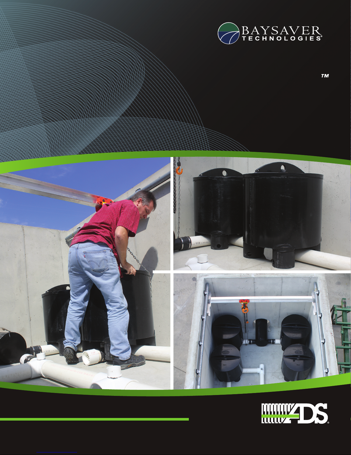
The BayFilter cartridge system is an ongoing commitment to state of the art stormwater treatment. The compound
spiral media configuration allows for a large filter surface area in a compact footprint. This configuration results
in the most efficient and effective stormwater filter available in the marketplace. The BayFilter is available in
multiple sizes with multiple media configurations to meet any flow rate and design consideration while being able
to target specific pollutants. A BayFilter System is typically a concrete structure (precast vault, manhole, or cast
in place structure) with a single or multiple BayFilter cartridges. Inside the structure the BayFilters are connected to
an outlet manifold through which the treated water exits the system.
BayFilter Cutaway
Plan View Profile View

The MosT ADVANCED NaMe iN WaTer MaNageMeNT soluTioNsTM
4
Stormwater treatment has unique requirements, which
often require the treatment of large volumes of water at
relatively high flow rates to high levels of pollutant removal
with long periods of time between maintenance intervals.
At BaySaver we believe it is our responsibility to engineer
a balance within these variables to provide effective
stormwater treatment at an exceptional value to our clients.
What makes for an effective and efficient stormwater filter?
A filter must be able to remove the pollutants of concern
and function for a reasonable period of time as defined by
industry and regulatory standards. A filter system should also
be designed to limit re-suspension or release of pollutants
that have been collected between maintenance periods.
The traditional pollutants of concern in stormwater is
sediment. Phosphorous, metals, turbidity, nitrogen, fecal
coliform, and bacteria are also pollutants of concern although
they are not commonly regulated nationwide. BaySaver
Technologies has completed both field and laboratory testing
of the BayFilter. Testing demonstrates BayFilter’s effectiveness
and efficiency at capturing the pollutants listed above.
Settling and filtration are the two primary methods to
remove pollutants from stormwater. Some settling of
particles and pollutants occurs as the influent enters the
filter vault. Settling typically removes the larger particles
and debris, it does not remove the small particles or any
dissolved materials. It is the filter which performs the
work of removing the very small particles, and dissolved
nutrients and metals. The media within a filter must be small
enough to intercept the tiny sediment particles which won’t
settle (fig. 1), and be capable of attracting and attaching
charged and elemental particles through ion exchange.
The area of media provided by a stormwater filter is an
important factor to consider when selecting and specifying a
filter system. The more surface area provided by the media,
the greater the potential flow through and across the media
and the greater the pollutant removal potential of the filter.
The vertically oriented and patented compound spiral media
BASIC PRINCIPLES OF STORMWATER FILTRATION
Figure 1: Coarse Industry Media
Figure 2: BayFilter Media

5
configuration of the BayFilter maximizes a media filter’s area
potential. The particle size of the media is also important with
respect to pollutant interception and adsorption. A tightly
packed, fine media (fig 2) captures a greater percentage of
fine and dissolved pollutants when compared to a loosely
packed, coarse media or a membrane media. A fine and
tightly packed media not only minimizes the interstitial
spaces between the media particles to optimize interception
of pollutants, it also maximizes the amount of surface area
in a given volume provided by the media for ion exchange.
The quantity of sediment a filter is capable of capturing is
a significant component to filter longevity. A filter must be
able to treat large quantities of sediment while maintaining
claimed flow rates and removal efficiencies. The sediment
loading capacity of the BayFilter is 350 pounds (158.7 kg) for
the 45 gpm (170.3 lpm) and 30 gpm (113.6 lpm) cartridges.
Surface area and loading rate contribute significantly to filter
longevity. Greater filter surface area (sf) allows for a reduced
loading rate (gpm/sf of filter media), which in turn increases the
service life of the filter. For example, a 10 square foot (0.9 m2)
filter with a loading rate of 1 GPM (3.8 l/min) per square foot
of filter area will pass 10 GPM (37.9 l/min). A 20 ft2filter with a
loading rate of 0.5 GPM (1.9 l/min) per square foot of filter area
will also pass 10 GPM (37.9 l/min). If one gallon of treated water
will occlude one square foot of filter area every 10 days, a 10 ft2
(0.9 m2) filter flowing at one GPM (3.8 l/min) will be expired in
100 days. A 20 ft2(1.9 m2) filter flowing at 0.5 GPM (1.9 l/min)
will be expired in 400 days. Increasing media area and
reducing flow rate has a beneficial impact on pollutant removal
and filter longevity and these are some of the core engineering
principles on which the BayFilter design is based.
BaySaver Technologies is committed to the purpose of
protecting public waterways. Permanently capturing
pollutants, effectively backwashing media, allowing media to
drain between storm events, and providing an economically
reasonable maintenance interval are key design parameters
for properly functioning stormwater filtration systems. The
BayFilter cartridge system helps meet and exceed these
key requirements needed to protect our water resources.
Bottom of Cartridge
Top of Cartridge
The MosT ADVANCED NaMe iN WaTer MaNageMeNT soluTioNsTM
6
BAYFILTER PRODUCT DETAILS
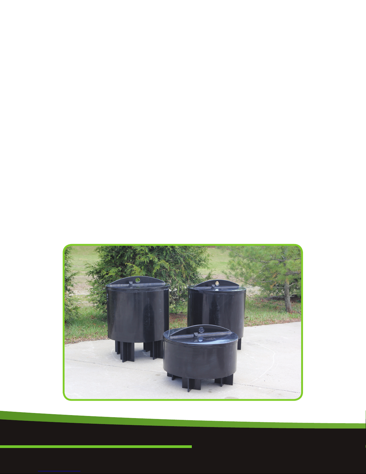
BayFilter 545
Size = 28” (711 mm) diameter
Weight = 250 lbs. (113 kg)
Media Area = 90 ft2(8.4 m2)
Flow Rate = 45 gpm (170 l/min)
Flow Rate per Square Foot = 0.50 gpm/ft2(20 l/min/m2)
Minimum Operational Head = 32” (813 mm)
Recommended Design Head = 34” (864 mm)
Sediment Capture Capacity = 350 lbs (159 kg)
Manifold Diameter = 6” (152 mm)
BayFilter 530*
Size = 28” (711 mm) diameter
Weight = 250 lbs. (113 kg)
Media Area = 90 ft2(8.4 m2)
Flow Rate = 30 gpm (114 l/min)
Flow Rate per Square Foot = 0.33 gpm/ft2(13 l/min/m2)
Minimum Operational Head = 30” (762 mm)
Recommended Design Head = 32” (813 mm)
Sediment Capture Capacity = 350 lbs (159 kg)
Manifold Diameter = 4” (102 mm)
BayFilter 522**
Size = 28” (711 mm) diameter
Weight = 125 lbs. (57 kg)
Media Area = 45 ft2(4.2 m2)
Flow Rate = 22.5 gpm (85 l/min)
Flow Rate per Square Foot = 0.50 gpm/ft2(20 l/min/m2)
Minimum Operational Head = 18” (457 mm)
Recommended Design Head = 20” (508 mm)
Sediment Capture Capacity = 175 lbs (79 kg)
Manifold Diameter = 3” (76 mm) NOTES: The 500 series is for
Total Suspended Solids (TSS) and
Phosphorous and utilizes EMC media.
*BayFilter 530 replaces BFC cartridge.
** BayFilter 522 replaces 545L cartridge.
BayFilter 545
BayFilter 530
BayFilter 522

7
BayFilter 645
Size = 28” (711 mm) diameter
Weight = 250 lbs. (113 kg)
Media Area = 90 ft2(8.4 m2)
Flow Rate = 45 gpm (170 l/min)
Flow Rate per Square Foot = 0.50 gpm/ft2(20 l/min/m2)
Minimum Operational Head = 32” (813 mm)
Recommended Design Head = 34” (864 mm)
Sediment Capture Capacity = 350 lbs (159 kg)
Manifold Diameter = 6” (152 mm)
BayFilter 630
Size = 28” (711 mm) diameter
Weight = 250 lbs. (113 kg)
Media Area = 90 ft2(8.4 m2)
Flow Rate = 30 gpm (114 l/min)
Flow Rate per Square Foot = 0.33 gpm/ft2(13 l/min/m2)
Minimum Operational Head = 30” (762 mm)
Recommended Design Head = 32” (813 mm)
Sediment Capture Capacity = 350 lbs (159 kg)
Manifold Diameter = 4” (102 mm)
BayFilter 622
Size = 28” (711 mm) diameter
Weight = 125 lbs. (57 kg)
Media Area = 45 ft2(4.2 m2)
Flow Rate = 22.5 gpm (85 l/min)
Flow Rate per Square Foot = 0.50 gpm/ft2(20 l/min/m2)
Minimum Operational Head = 18” (457 mm)
Recommended Design Head = 20” (508 mm)
Sediment Capture Capacity = 175 lbs (79 kg)
Manifold Diameter = 3” (76 mm)
NOTES: The 600 series is for enhanced
metals treatment.
BayFilter 645
BayFilter 630
BayFilter 622
The MosT ADVANCED NaMe iN WaTer MaNageMeNT soluTioNsTM
8
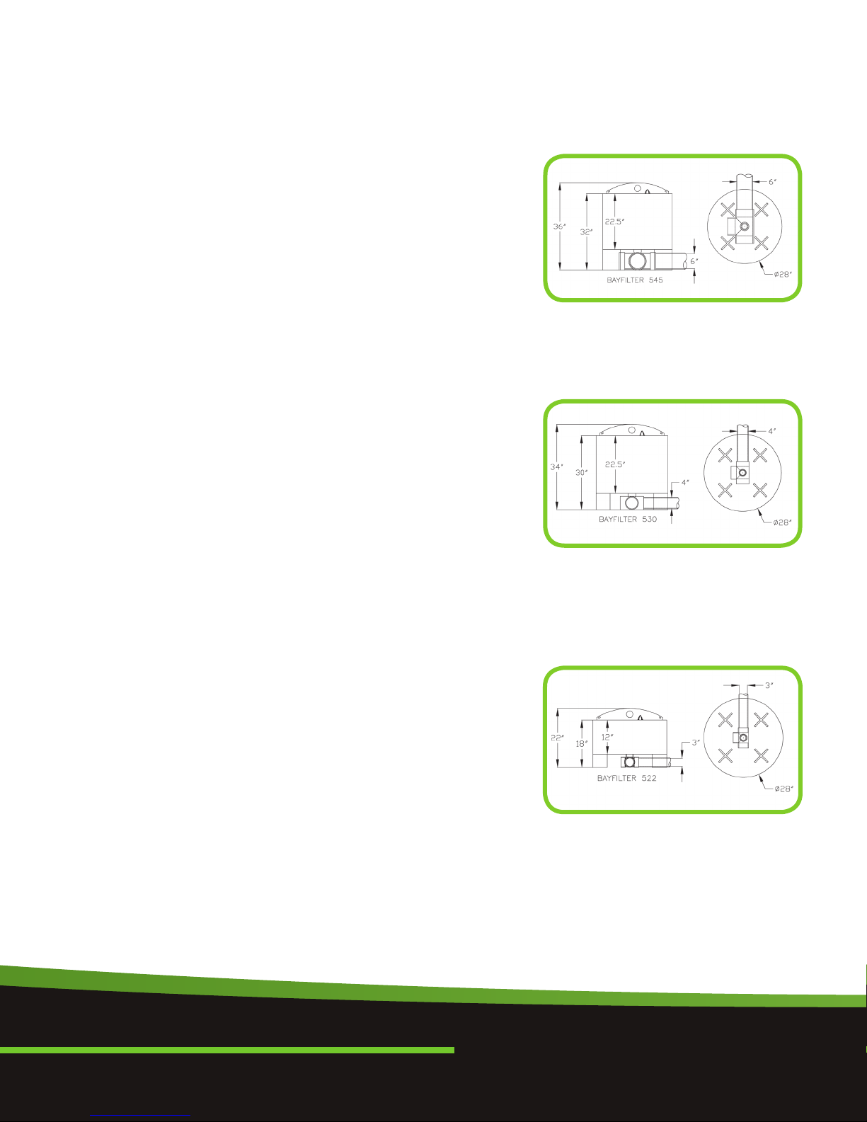
Stormwater runoff enters the manhole or concrete structure
via an inlet pipe and begins to fill the structure. When the
water surface elevation in the vault/manhole reaches the
minimum operating level, water flows through the BayFilter
driven by a hydrostatic head. Within the BayFilter, the water
flows through a proprietary filter media and drains via a
vertical pipe. The vertical pipe is connected to the under
drain system, which conveys filtered water to the outfall.
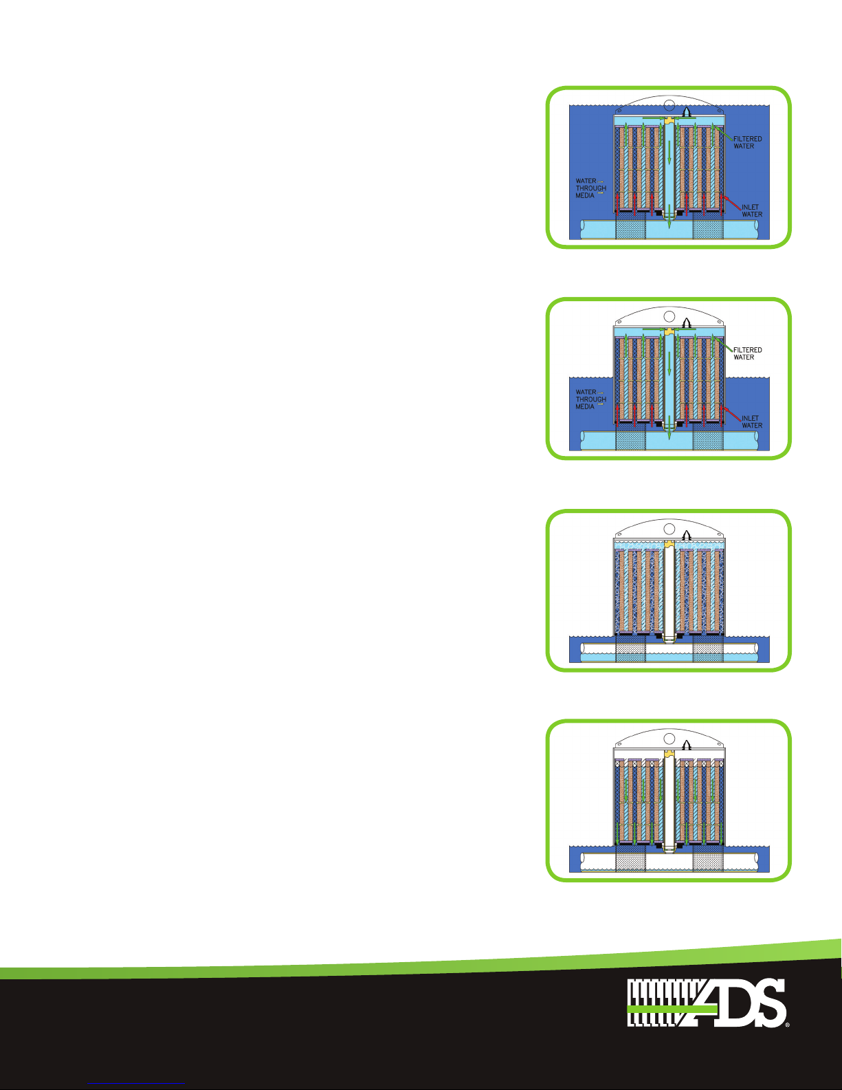
During a typical storm event, the BayFilter
system has four cycles:
A. BayFilter cartridge fills and releases air
B. Positive head filtration
C. Siphon (negative head) filtration
D. Siphon break and hydrodynamic backwash
The cycle operation of a BayFilter is as follows:
A. BayFilter cartridge fill and air release: The BayFilter vault
and BayFilter cartridges fill when stormwater flow enters
the system. As the vault fills, water enters the BayFilter
cartridge through the inlet plate on the bottom. Air is
purged from the media spiral and filter housing during
this process.
The air release is critical for the proper functioning of the
siphon. The siphon draws flow through the BayFilter
during periods of low water in the vault.
BAYFILTER OPERATION
BayFilter Cutaway
BayFilter Vault
Cartridge Filling
9
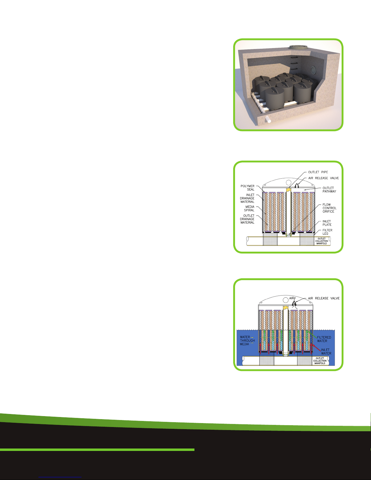
B. Positive Head Filtration: Water enters the Filter from the
bottom of the filter housing and travels upward through
the inlet-flow conduit-spiral. From the inlet spiral,
untreated water flows horizontally through the
engineered media. Treated water exits the engineered
media and flows into the outlet-flow conduit-spiral.
Treated water flows vertically to the top of the cartridge
where it can exit through the outlet pipe—please see
product details (pg.6) for operating head levels. Finally,
filtered water leaves the system via the outlet.
C. Siphon (Negative Head) Filtration: After the water level in
the vault falls below the top of the filter cartridge-
minimum operating head level, a siphon is established
and water will continue to flow through the filter media
until the siphon is broken. During siphon, the water level
in the vault will decrease until it reaches the inlet plate
of the BayFilter.
D. Siphon Break and Hydrodynamic Backwash: When
the water level drops below the inlet plate, air enters
the filter and the siphon breaks. Once the siphon breaks,
a gravity-driven backwash occurs with all of the water
flowing from the outlet pathway backwards through the
filter media. This backwash has the effect of dislodging
particles captured in the filtration layers and
re-establishing porosity. Dislodged particles are
transported back in to the filter vault and accumulate
on the filter vault floor.
Each BayFilter has a maximum flow rating. At this flow,
each cartridge can treat the specified total sediment
load before requiring maintenance. BayFilter flow may
also be custom regulated to meet specified design
parameters by modifying the flow control orifice. Please
contact BaySaver for custom design requirements.
Backwash
Siphon Filtration
Siphon Break
Positive Filtration

The MosT ADVANCED NaMe iN WaTer MaNageMeNT soluTioNsTM
10
The BayFilter cartridge system design is easily
completed in four phases:
A. BayFilter System Configuration
B. BayFilter Site Plan Placement
C. BayFilter System Sizing
D. Final Check
The design process can be iterative until the determined
design parameters are satisfied. Some of the items to
consider when designing a stormwater filtration system:
•Site specific constraints and proposed
BayFilter system location
•BayFilter system configuration—on-line or off-line
•Pretreatment requirements
•Operating head
•Treatment efficiency requirements and local regulations
•Pollutant loading (sediment load)
•Treatment flow rates and hydraulics
•Maintenance intervals
BAYFILTER SYSTEM CONFIGURATION
BayFilter systems can accommodate any treatment
flow requirement. The peak design flow through the
storm drain system will be significantly greater than
the treatment design flow through BayFilter. It is a best
practice to only convey the required treatment flow
through a stormwater filter and this will extend the filter’s
life cycle. Conveying the peak design flow around a
stormwater filter is considered off-line treatment.
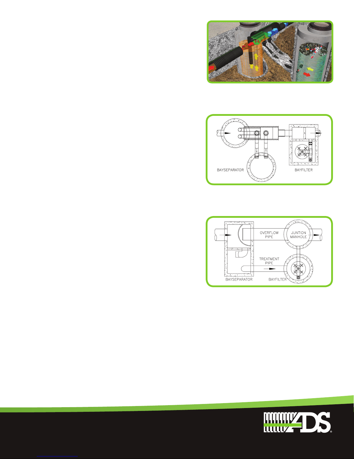
Off-Line Design
Schematics of off-line BayFilter systems are shown below.
In Figure 1, the bypass structure diverts treatment flows to
the BayFilter system and allows high flows to pass to a
separate outfall. The bypass structure will feature flow
controls designed by an engineer to ensure that the required
treatment flows are sent to the BayFilter. In Figure 2, this
same concept is accomplished within a 3-chamber vault.
In stormwater filter system installations, sediment
will accumulate in the filter cartridge and on the vault
floor. In off-line installations, high intensity flows are
routed away from the vault minimizing the risk of re-
suspending the sediment accumulated on the vault
floor. In online applications it is possible for high
flows to mobilize and release this sediment.
BAYFILTER SYSTEM DESIGN & SIZING
Figure 1: Offline Configuration
External Bypass
Figure 2: Inline Configuration
Internal Bypass
11
Operating Head
Head is required to activate BayFilter flow and establish
siphon flow. The height of individual BayFilter cartridges
will determine the operating head. Please consult
product details for individual operating head levels. The
drainage system and network does not need to provide
the operating head. Filter systems can easily be designed
on sites where the elevation drop of the hydraulic grade
line is less than the required operating head of the filter.
Consult BaySaver Technologies Engineering Department
for verification based on your particular site conditions.
Pretreatment
Regional regulations may require pretreatment of
stormwater flows prior to flow entering filters. Pretreatment
will remove a portion of the influent pollutant load. This
will lessen the pollutant load received by a filter and
potentially increase the maintenance interval duration.
The BaySeparator™ system (Figures 3 & 4) is an ideal
hydrodynamic separator that removes sediments and
floatables from stormwater runoff. Please contact your
ADS representative for additional pre-treatment options.
BAYFILTER SITE PLAN PLACEMENT
Locating a BayFilter system on your site will be determined
by giving consideration to several factors including:
maintenance access, the unit’s footprint, available head,
available depth, and the surface elevation of the receiving
waters. A BayFilter system must be installed in an area that
is accessible to maintenance equipment. The maintenance
of a BayFilter system requires a vacuum truck as well as
the removal and replacement of the filter cartridges. The
manhole covers, and or access hatches of the BayFilter
must be placed in locations that can be easily reached
by such a vehicle. Consult the BaySaver Technologies
Engineering Department for expert assistance.
Traditional BaySeparator
Figure 4: BaySeparator FS Unit
Pre-Treatment Configuration
Figure 3: Traditional BaySeparator
Pre-Treatment Configuration

The MosT ADVANCED NaMe iN WaTer MaNageMeNT soluTioNsTM
12
BayFilter System Sizing
Each BayFilter system relies on a collection of individual
BayFilter cartridges to achieve the desired removal
efficiency. Accurately determining the required
number of filters is important to efficient operation.
Undersizing a system may lead to shorten service life.
A valuable stormwater treatment system will
be provided when the three design parameters
listed below are given consideration.
•Jurisdiction – specific sizing requirements
•Flow capacity of the system
•Treated sediment load of the system
Each parameter results in a required number of BayFilter
cartridges. After computing the number of filters for each
parameter, determine which requires the most filters, and
this is is the limiting design parameter and the number
of required BayFilter cartridges for your drainage area.
Jurisdiction
Local regulatory requirements play a significant role
in any BayFilter design. Depending on the jurisdiction
in which the project site is located, the engineer may
have to meet minimum treatment flow rates, treatment
volumes or some other criteria such as filter bed area.
Some jurisdictions specify a methodology for calculating
a minimum treatment flow rate for a given site.
Flow Capacity
Regulatory requirements will determine water quality
treatment values. The BayFilter system is simply applied by
the design professional to their computed values. Typically,
the primary treatment value is treatment flow rate (QTRT).
This value tells us the rate at which flow must pass through
a filter system. Other common treatment values are water
quality volume and phosphorous load reduction. Please
contact BaySaver Technologies Engineering Department
when designing to volume or phosphorous requirements.
The minimum number of BayFilter cartridges can be
determined by dividing the treatment flow rate by flow
rate of the BayFilter you have chosen. This calculation
provides the minimum number of BayFilters that will be
necessary to fully treat the water quality flow from the
site. The step-by-step procedure is shown below.
BayFilter
Cartridge
Treatment
Flow Rate
gpm (l/min)
Treatment
Volume
f3(m3)
522 22.5 (85.1) 1250 (35.4)
530 30.0 (113.6) 2500 (70.8)
545 45.0 (170.3) 2500 (70.8)
BayFilter
Cartridge
Treatment
Flow Rate
gpm (l/min)
Treatment
Volume
f3(m3)
622 22.5 (85.1) 1250 (35.4)
630 30.0 (113.6) 2500 (70.8)
645 45.0 (170.3) 2500 (70.8)
BayFilter Series 500
System Sizing Table
BayFilter Series 600
System Sizing Table
13
1. Determine the required treatment flow rate (QTRT)
based on locally approved methodologies for
the project site. This may involve the use of the
Rational Method, TR-55 or another locally specified
hydrologic model. If a locally approved methodology
is not specified, BaySaver Technologies recommends
using one of these commonly accepted models.
2. Using the BayFilter cartridge treatment flow rate
(QBayFilter), calculate the minimum numbers of BayFilter
cartridges required to treat that flow using Equation 1.
Refer to the product details for BayFilter flow rates.
The minimum number of BayFilter cartridges is
equal to the maximum treatment flow rate divided by
QBayFilter, rounded up to the next whole number.
Sediment Load Capacity
BayFilter sediment load capacity allows the professional
designer to establish the maintenance interval for the
stormwater system. Establishing a sediment load is a
straight forward computation which may be completed
once the number of BayFilter cartridges required to
treat the flow is known. With the known filter quantity, a
designer will establish the sediment load capacity for the
BayFilter system, and compare this value to the annual
sediment load for the site. The following equations may
be used to compute these values and help determine
BayFilter suitability for a specific site design.
Sediment Load Capacity Calculations
1. Calculate the annual treated runoff volume according
to Equation 2. VTRT is the annual treated runoff
volume, Pis the average annual precipitation (in
inches), Ais the area of the site (in acres), c is the
runoff coefficient of the site (c is dimensionless), and
% Capture is the fraction of the total annual runoff
that is treated by the stormwater quality system. If %
Capture is not otherwise specified, a default value of
0.90 can be used. Please check local regulations.
2. Using the annual treated runoff volume, calculate the
anticipated total system sediment load to BayFilter
according to Equation 3. In Equation 3, Lis the mass
of sediment that BayFilter is exposed to annually
(in pounds), VTRT is the annual treated runoff volume
as calculated in step 1 (in ft3), and TSSIN is the
influent concentration of TSS in the runoff (in mg/L).
The influent TSS concentration (TSSIN) depends
greatly on the site and the surrounding land use.
In the absence of readily available data, BaySaver
Technologies recommends using a minimum event
mean concentration (EMC) TSS value of 60 mg/l.
The impact on the filter cartridge will also be less if
Equation 1
Equation 2
Equation 3

The MosT ADVANCED NaMe iN WaTer MaNageMeNT soluTioNsTM
14
the filtration system is preceded by pretreatment. In
these cases, the influent TSS to the BayFilter system
need to be reduced to reflect pretreatment sediment
removal. The BaySaver Technologies’ Engineering
Department can assist with these calculations.
3. Once the total annual system sediment load (L) is
calculated, the engineer must ensure that the number
of cartridges specified will be able to remove that
sediment load at the specified design flow rate. Divide
the total system sediment load L by the capacity
of each BayFilter and note the associated BayFilter
flow rate. Round up to the next whole number to get
the minimum number of BayFilters required. This
quantity of BayFilters will need to treat this sediment
load at the required flow rate per BayFilter. The
BaySaver Technologies Engineering Department is
available to assist with the required calculations.
FINAL CHECK
It may be beneficial to perform a Final Check on the
BayFilter design for your site. The BaySaver Engineering
Department is available to assist you with this function.
Standard Details and Notes
Standard details are available on the Website at
www.BaySaver.com or by calling 1.800.229.7283.
BayFilter Configurations
BayFilter Systems include the four typical concrete
structures: manhole, precast vault, box culvert, and cast
in place. BaySaver Technologies can also design BayFilter
systems with Nyloplast structures, and HP Pipe manholes.
BayFilter systems in manholes have a small footprint
and easily fit into site plans. Manhole BayFilter systems
are ideal for applications downstream from water quality
detention structures. Please consult with the BaySaver
Technologies Engineering Department for more details.
When designing access for a BayFilter utilizing manhole
frame and covers a minimum of 30” (762) diameter
should be used, however, it is recommended that a
36” (914) diameter opening is used to provide ample
access for filter replacement and maintenance. In each
BayFilter system, the BayFilters are arranged so that
a maintenance worker can stand on the floor of the
manhole while installing or removing the cartridges.
Example of a manhole
BayFilter system
Example of a precast
vault BayFilter system

15
INSTALLATION
Note: BayFilters are not recommended to be used as
erosion control during site construction operations.
BayFilters should remain offline or uninstalled until site
stabilization has occurred. Please contact your local
ADS or BaySaver representative if you should have any
questions.
1. Contact utility locator to mark any nearby underground
utilities and make sure it is safe to excavate.
2. Reference the site plan and stake out the location of the
BayFilter manhole/vault.
3. Excavate the hole, providing any sheeting and shoring
necessary to comply with all federal, state and local
safety regulations.
4. Level the subgrade to the proper elevation. Verify the
elevation against the manhole/vault dimensions, the
invert elevations, and the site plans. Adjust the base
aggregate, if necessary.
5. Have the soil bearing capacity verified by a licensed
engineer for the required load bearing capacity. On solid
subgrade, set the first section of the BayFilter manhole/
vault.
6. Check the level and elevation of the first section to
ensure it is correct before adding any riser sections.
7. If additional section(s) are required, add a watertight
seal to the first section of the BayFilter manhole/vault.
Set additional section(s) of the manhole/vault, adding a
watertight seal to each joint.
8. Install the outlet pipe in BayFilter manhole/vault.
9. Install the inlet pipe to the BayFilter manhole/vault.
10. Install the trolley system (if applicable).
a. Attach the mounting brackets to the track.
b. Each track is split in sections. The length and
number of sections vary depending on the vault.
It is generally better to start installing longer track
sections first. Hold a section in place and align the
top of the brackets with the ceiling of the vault. Mark
the center of the hole in each bracket and remove the
track.
c. Using a hammer drill and ¼” (6 mm) bit, drill a hole
approximately 3” (76 mm) deep at each mark.
d. Hold the track back in place and realign the brackets
with the holes. Place a plastic spacer block behind
each bracket and using the supplied ¼” (6 mm) x 3¼”
(83 mm) anchor bolts mount the track in place. Only
install one section of track at this stage.
Modular Vault Assembly
Vault End Section
Trolley System

The MosT ADVANCED NaMe iN WaTer MaNageMeNT soluTioNsTM
16
e. Repeat this procedure on the opposite wall of the
vault directly across from the first section.
f. Bolt the 4 trolleys to the aluminum I-beam as shown
in the attached diagram. Make sure that the wheels
for each trolley are mounted an equal distance from
the top of the I-beam.
g. Lift the I-beam in to place and insert the trolleys in to
the track.
h. Using the supplied couplers, install the second
sections of track via the same procedure. Continue
until the track runs the length of the vault or as
designed.
11. Install the PVC manifold. Glue all PVC joints with the
exception of the BayFilter cartridge coupling. See Parts
List drawing.
12. After the site has stabilized, remove any accumulated
sediment or debris from the vault.
13. Install the Bayfilter Vertical Drain Down Modules (VDDM)
to the manifold system (if applicable).
14. Install a row of flow disks and the BayFilter cartridges.
Place each cartridge so the handle points across the
vault. Make sure the air valve is on the side closer to the
outlet.
15. Place one full set of one Hold Down Bar and two Retainer
Brackets into place. Mark and drill two 5/8” holes for
each bracket. After fully anchoring Retainer Brackets,
place the left end of the Hold Down Bar in position. Slide
right end into bracket and secure with U-Bolt.
16. Repeat steps 14 and 15 for each set of BayFilter
Cartridges and Hold Down Bar until the whole system
is installed. See Parts List drawing for Hold Down Bar
placement.
Tool List
• PVC glue and primer
• Crane/lifting mechanism to lower the cartridges in the
vault (each cartridge weighs 230-350 lbs (104-159))
• Screwdriver or nut driver for Fernco®couplers
• Hammer and soft blow hammer
• Saw (in case PVC Sch 40 piping
length needs to be adjusted)
• Hammer drill
• ¼” (6 mm) and 5/8” (16 mm) concrete drill bit
• ¾” (19 mm) wrench
Filter Tee
Flow Disc
Chain Hoist System
BayFilter Vault Overview
Drain Down Module
Filter Placement
Hold Down Bar
and Bracket
Vault Internal Assembly
17
Pre-Assembled Manifold
In some areas the vaults can be provided with pre-in-
stalled manifold systems. Please contact your local ADS
or BaySaver representatives for additional details.
Inspection and Maintenance
The BayFilter system requires periodic maintenance
to continue operating at the design efficiency. The
maintenance process is comprised of the removal
and replacement of each BayFilter cartridge,
vertical drain down module; and the cleaning of
the vault or manhole with a vacuum truck.
The maintenance cycle of the BayFilter system will be
driven mostly by the actual solids load on the filter. The
system should be periodically monitored to be certain
it is operating correctly. Since stormwater solids loads
can be variable, it is possible that the maintenance cycle
could be more or less than the projected duration.
BayFilter systems in volume-based applications
are designed to treat the WQv in 24 to 48 hours
initially. Late in the operational cycle of the BayFilter,
the flow rate will diminish as a result of occlusion.
When the drain down exceeds the regulated
standard, maintenance should be performed.
When a BayFilter system is first installed, it is recommended
that it be inspected every six (6) months. When the filter
system exhibits flows below design levels the system should
be maintained. Filter cartridge replacement should also
be considered when sediment levels are at or above the
level of the manifold system. Please contact the BaySaver
Technologies Engineering Department for maintenance
cycle estimations or assistance at 1.800.229.7283.
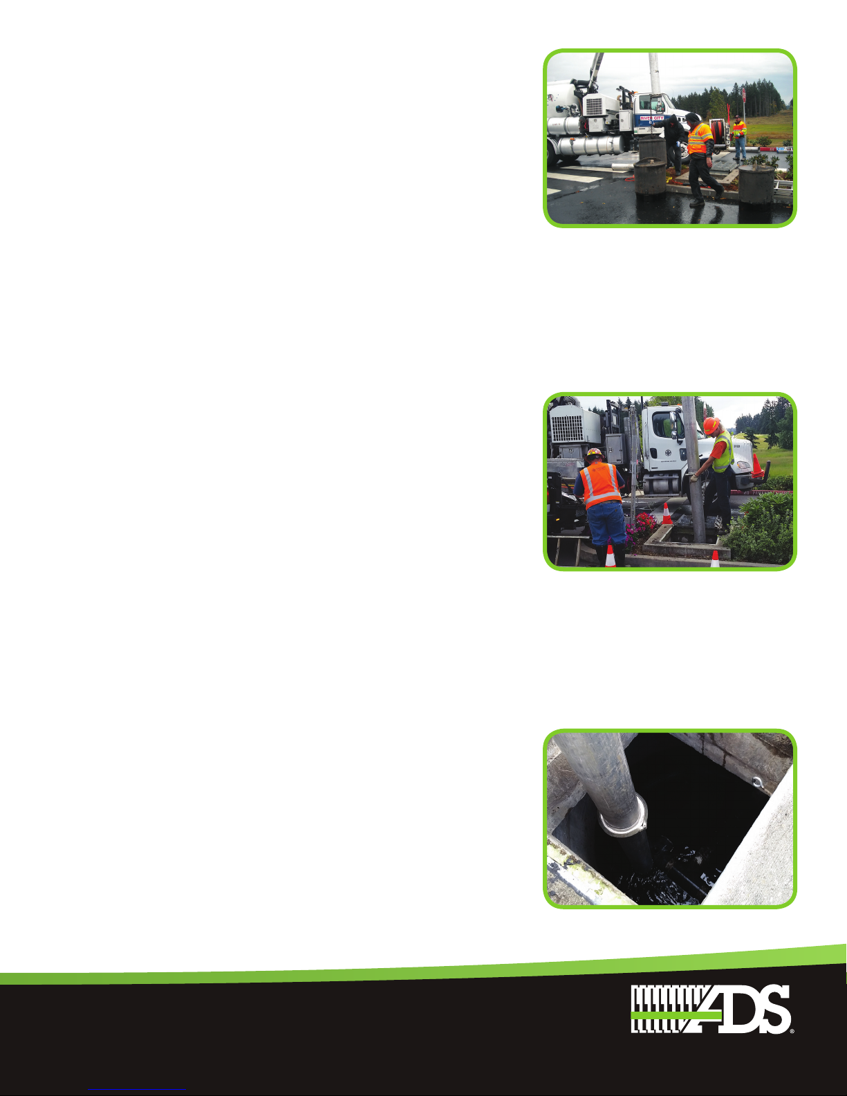
Maintenance Procedures
1. Contact BaySaver Technologies for replacement filter
cartridge pricing and availability at 1-800-229-7283.
2. Remove the manhole covers and open all
access hatches.
3. Before entering the system make sure the air
is safe per OSHA Standards or use a breathing
apparatus. Use low O2, high CO, or other applicable
warning devices per regulatory requirements.
4. Using a vacuum truck remove any liquid and
sediments that can be removed prior to entry.
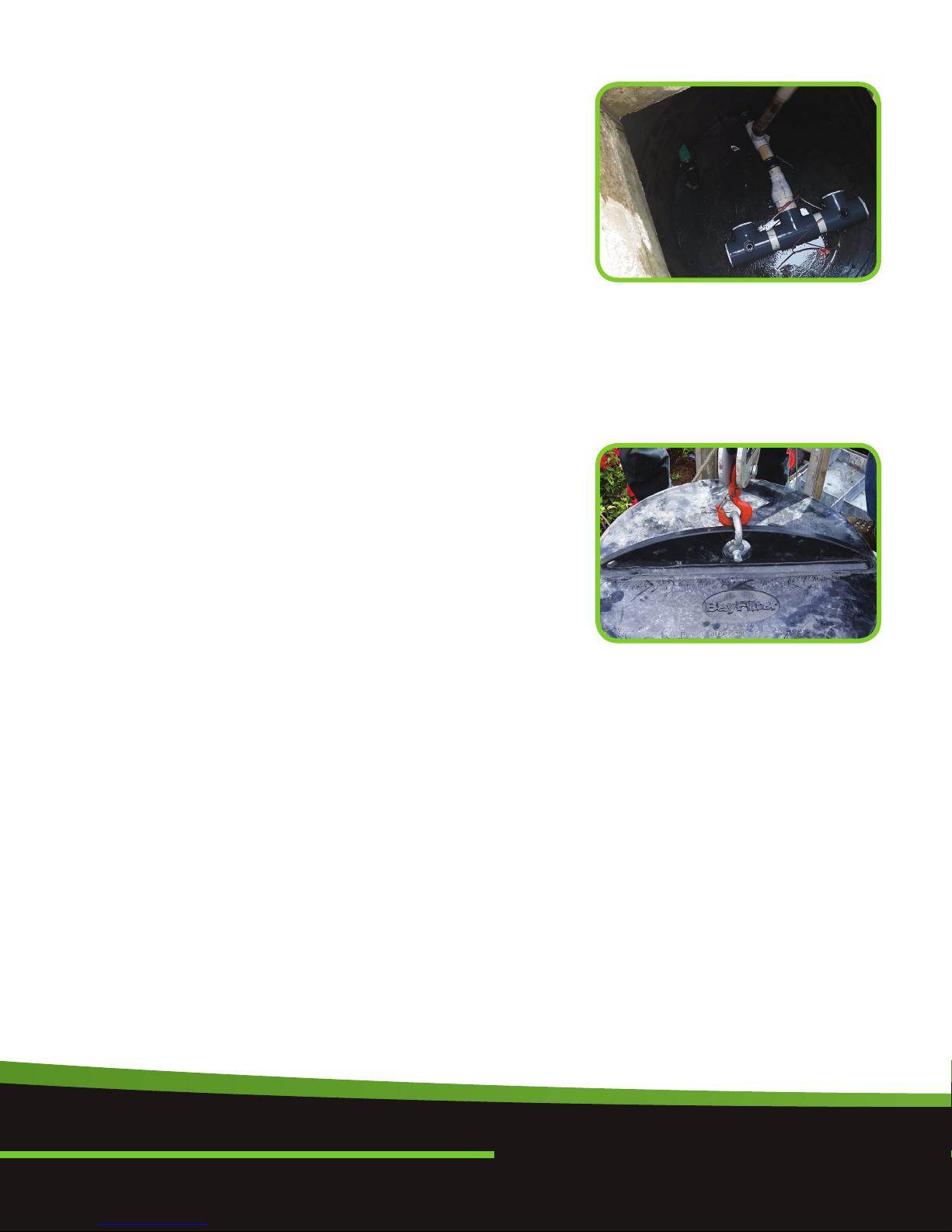
5. Using a small lift or the boom of the vacuum truck,
remove the used cartridges by lifting them out.
6. Any cartridges that cannot be readily lifted
can be easily slid along the floor to a location
BayFilter System Cleanout
Vactor Truck Maintenance
Jet Vactoring Through Access Hatch
The MosT ADVANCED NaMe iN WaTer MaNageMeNT soluTioNsTM
18
they can be lifted via a boom lift.
7. When all the cartridges have been removed, it is
not practical to remove the balance of the solids
and water. Loosen the stainless clamps on the
Fernco couplings for the manifold and remove
the drain pipes as well. Carefully cap the manifold
and the Ferncos and rinse the floor, washing away
the balance of any remaining collected solids.
8. Clean the manifold pipes, inspect, and reinstall.
9. Install the exchange cartridgess and close all covers.
10. The used cartridges may be sent back to
BaySaver Technologies for recycling.
BayFilter Availability and Cost
BayFilter systems are available throughout the
United States from BaySaver Technologies. Material,
installation, and maintenance costs vary with location.
For BayFilter pricing in your area, please contact
BaySaver Technologies at 1-800-229-7283.
BayFilter cartridges and outlet components can be
shipped anywhere in the world. Manholes and precast
vaults are also supplied by BaySaver Technologies as
part of a complete stormwater filtration system.
BayFilter Specifications
Products
A. Internal components: all components including
concrete structure(s), PVC manifold piping
and filter cartridges, shall be provided by
BaySaver Technologies 1-800-229-7283).
B. PVC manifold piping: all internal PVC pipe and
fittings shall meet ASTM D1785. Manifold piping
shall be provided to the contractor pre-cut and/or pre-
assembled. Minor field modifications may be necessary.
C. Filter cartridges: external shell of the filter cartridges
shall be substantially constructed of polyethylene
or equivalent material acceptable to the manufacturer.
Filtration media shall be arranged in a spiral layered
fashion to maximize available filtration area. An orifice
flow control (i.e. flow disk) shall be supplied with each
cartridge to restrict the flow rate to a maximum of
45 gpm (170 l/min).
D. Filter media: filter media shall be a proprietary mix
produced by BaySaver Technologies and may consist
of the following materials: zeolite, perlite, and activated
alumina and/or other materials required to meet the
project pollutant removal requirements.
Manifold Tee View of a Cleaned System
Cartridge Hoist Point

19
E. Precast concrete vault: concrete structures shall be
provided according to ASTM C478, C858, and C913.
The materials and structural design of the devices shall
be per ASTM C478 and ACI 318. Precast concrete shall
be provided by BaySaver Technologies.
Performance
A. The stormwater filter system shall be capable of
treating 100% of the required treatment flow at full
sediment load conditions.
B. The stormwater filter system’s cartridges shall have
no moving parts.
C. The stormwater treatment unit shall be designed to
remove a minimum of 80% of suspended solids,
60% of total phosphorus, 50% of turbidity, 40% of total
copper, and 40% of total zinc. All filter designs shall
comply with local regulations.
D. The stormwater filtration system shall not have any
components that leach nitrates, phosphates or metals.
E. The stormwater filtration cartridge shall be equipped
with a hydrodynamic backwash mechanism to extend
the filter’s life and optimize its performance.
F. The stormwater filtration system’s cartridges shall have
a treated sediment capacity for 80% TSS removal
between 150-350 lbs (68-159 kg).
When BayFilter is initially installed, we recommend
that an inspection be performed on the system in the
first six (6) months. After that, the inspection cycle
typically falls into an annual pattern given normal
storm occurrence and actual solids loads.
When BayFilter exhibits flows below design levels,
the system should be inspected and maintained as
soon as practical. If flow monitoring is not available,
BayFilter cartridges should be replaced when sediment
levels are at or above the top of the manifold.

The MosT ADVANCED NaMe iN WaTer MaNageMeNT soluTioNsTM
20
1-800-821-6710 www.ads-pipe.com
1-800-229-7283 www.baysaver.com
ADS “Terms and Conditions of Sale” are available on the ADS website, www.ads-pipe.com
The ADS logo and the Green Stripe are registered trademarks of Advanced Drainage Systems, Inc.
BayFilterTM is a registered trademark of BaySaver Technologies, Inc.
© 2018 Advanced Drainage Systems, Inc. #10951 01/18 MH
The MosT ADVANCED NaMe iN WaTer MaNageMeNT soluTioNsTM
Table of contents


