Dean Portable Filters MF90 Series User manual

Dean, a member of the Commercial Food Equipment Service Association, recommends using
CFESA Certified Technicians.
Price: $6.00
24-Hour Service Hotline 1-800-551-8633 819-5711
05-99
MF90 Series Portable Filters (CE)
Operation, Service & Parts Manual
MF90-110
"U" & "AU" CONFIGURATIONS
CE ONLY

Please read all sections of this manual and retain for future reference.
Installation, maintenance, and repairs should be performed by your Dean Factory
Authorized Service Agency.
WARNING!
SAFE AND SATISFACTORY OPERATION OF YOUR EQUIPMENT DEPENDS ON
ITS PROPER INSTALLATION. INSTALLATION MUST CONFORM TO LOCAL
CODES, OR IN THE ABSENCE OF LOCAL CODES, WITH THE U.S. NATIONAL
ELECTRIC CODE, NFPA 70-1984 (OR LATEST EDITIONS) OR APPROPRIATE
EUROPEAN COMMUNITY/NATIONAL CODES/STANDARDS.
WARNING!
ELECTRICAL GROUNDING INSTRUCTIONS
THIS FILTER IS EQUIPPED WITH A THREE-PRONG, GROUNDED PLUG FOR
YOUR PROTECTION AGAINST SHOCK HAZARD AND SHOULD BE PLUGGED
DIRECTLY INTO A PROPERLY GROUNDED, THREE-HOLE RECEPTACLE. DO
NOT CUT OFF, REMOVE OR OTHERWISE BYPASS THE GROUNDING PRONG
ON THIS PLUG.
IF IT IS NECESSARY TO USE AN EXTENSION CORD, IT MUST BE A THREE-
CONDUCTOR, GROUNDED CORD OF 16 GAUGE OR GREATER.
CAUTION
DO NOT FILTER MORE THAN ONE FRY TANK AT A TIME.
HOT FLUID – DO NOT FILL BEYOND MAXIMUM FILL LINE
LOCATED ON THE OIL CONTAINER.
CAUTION
THIS FILTER UNIT IS NOT SUITABLE FOR OUTDOOR USE.
WHEN OPERATING THIS UNIT, IT MUST BE PLACED ON A
HORIZONTAL SURFACE.
CAUTION
THIS FILTER UNIT IS NOT SUITABLE FOR INSTALLATION IN AN
AREA WHERE A WATER JET COULD BE USED, AND THAT THIS
APPLIANCE MUST NOT BE CLEANED BY A WATER JET.
IF THIS FILTER UNIT IS CLEANED WITH WATER, DISCONNECT
THE UNIT FROM POWER SOURCE BEFORE CLEANING AND
THOROUGHLY DRY THE FILTER UNIT BEFORE
RECONNECTING TO ELECTRICAL POWER SOURCE.

2
Micro Flo - 90 Series (CE) Portable Filtration Systems
Models MF90-U/110 & MF90-AU/110
OPERATION, SERVICE AND PARTS MANUAL
TABLE OF CONTENTS PAGE
1. Parts Ordering And Service Information……………….…........... 2
2. Important Information……………………………………….......... 3
3. Installation………………………………………………….........….4
4. Daily Operation……………………...…………………….........….. 5
5. Cleaning and maintenance………………………………..........….. 8
6. Troubleshooting …………………....………………….........….….. 9
7. Parts Guide……...……………………………………….........…….13
8. Wiring Diagrams for MF90-U/110 and MF90-AU/110 Filters...... 16
1. PARTS ORDERING AND SERVICE INFORMATION
1.1 ORDERING PARTS:
Customers may order parts directly from their
local Authorized Parts Distributor. For this
address and phone number, contact your
Maintenance & Repair Center or call the
factory. The factory address and phone number
are on the cover of this manual.
To speed up your order, the following
information is required:
Model Number
Type
Serial Number
With/Without Heater
Optional Equipment
Item Part Number
Quantity Needed
1.2 SERVICE INFORMATION:
Call the Dean Service Hotline number on the
cover of this manual or 1-318-865-1711 for the
location of your nearest Maintenance & Repair
Center. Always give the model and serial
numbers of your filter and fryer.
To assist you more efficiently, the following
information will be needed:
Model Number
Type
Serial Number
With/Without Heater
Optional Equipment
Nature of Problem
Any other information which may be helpful in
solving your service problem

3
2. IMPORTANT INFORMATION
2.1 GENERAL:The MF-90 portable oil
filters may be used with a variety of Dean
fryers, as well as other manufacturers’
equipment.
The used oil may be drained by gravity
(MF90-U/110) from the fryer into the
filter pan, or, on some models, MF90-
AU/110, removed from the fryer by use of
a suction/return hose. It is then pumped
back into the fryer vessel by means of the
suction/return hose and nozzle assembly.
Filtering is accomplished through two
sheets of replaceable filter paper assisted
by a micro pre-coat filter powder.
2.2 OPERATING CONTROLS:
Two types of portable filters are available.
The most common is “return only”.
Primary filter control on the MF90-U/110
model is a two-position switch (on/off), or
on units with the optional heater, a three-
position switch (on/off/heater) is used.
The other type is “suction/return”.
Control on the MF90-AU/110 is by a
three-position switch (in/off/out). A pair
of swing-type check valves controls the
direction of oil flow. If any of these units
has an optional pan heater, the heater
switch is also mounted on the panel.
In many cases, a 60-minute timer may also
be activated to start the unit.
2.3 SAFETY FEATURES: On the
larger capacity filters, a 5-amp (230V) or a
7-amp (115V) circuit breaker switches the
power OFF if an overload occurs.
NOTE:If circuit breaker is triggered, depress
the reset button to activate the circuit
after the failure has been detected and
fixed.
2.4 RATING PLATE:Information on
this plate includes the model and serial
numbers as well as electrical requirements.
This data is essential when contacting the
factory about a unit or ordering special
parts.
2.5 PRE-INSTALLATION:
a. STANDARDS: Usage of this filter
unit must be in accordance with all
applicable state and local codes.
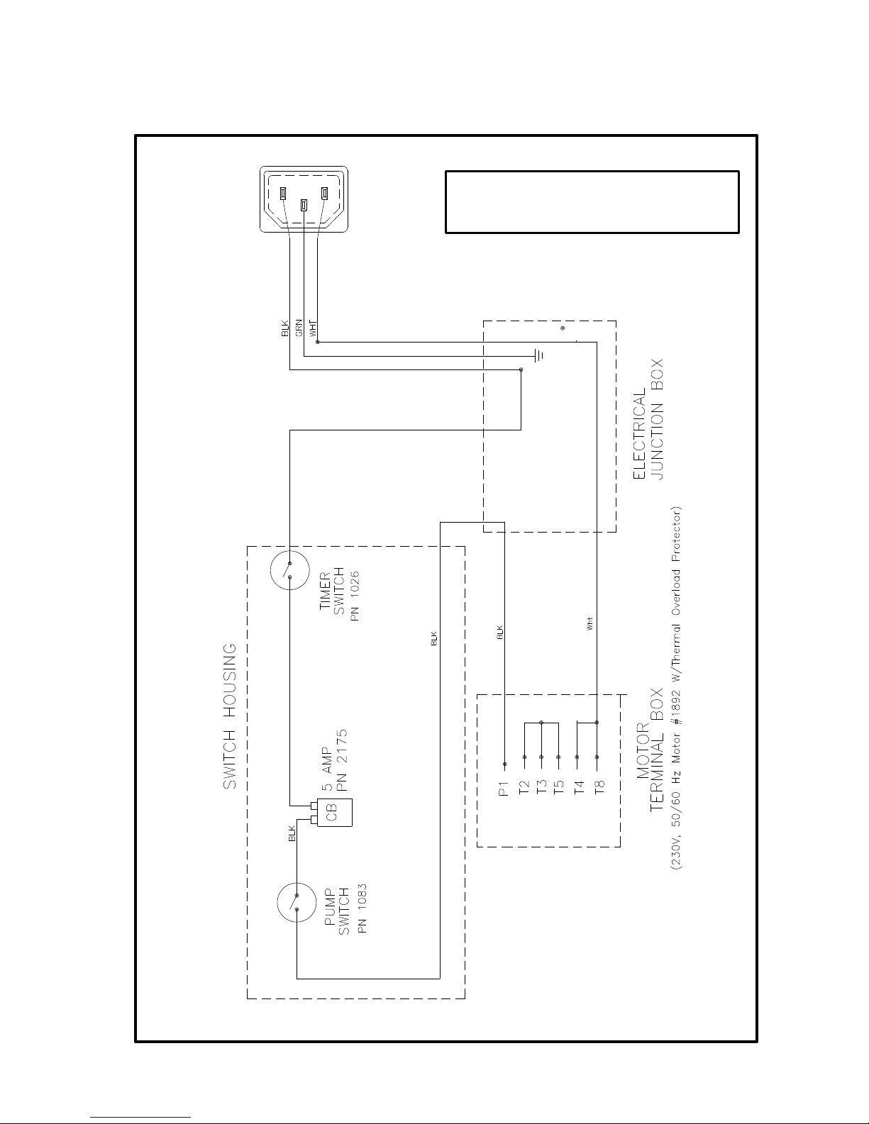
b. ELECTRICAL CONNECTIONS:
This unit requires connection to a
230V, 15 amp electrical supply. The
unit is equipped with a 3-wire, 16
AWG power cord. If an extension
cord must be used, it must be a three
conductor, grounded power cord of at
least 16 AWG.
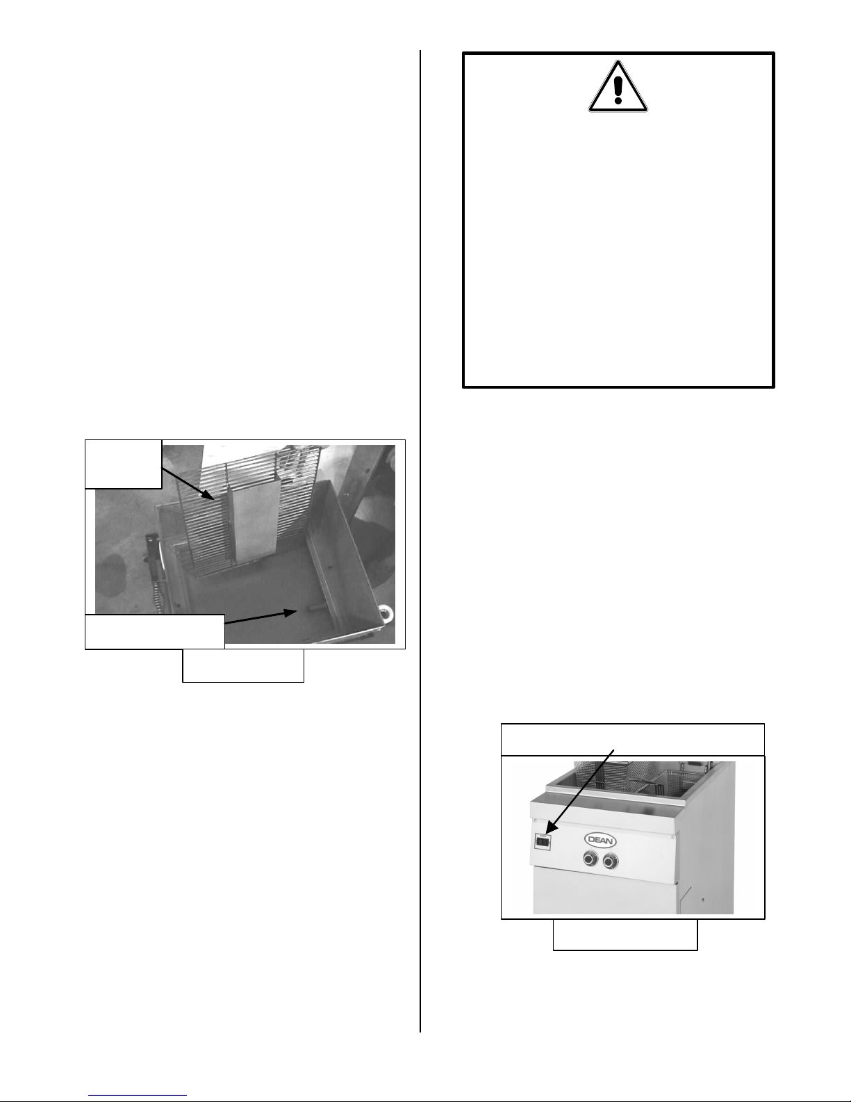
2.6 UNPACKING THE FILTER:
Before unpacking, make certain the
container is upright. Unpack the filter
carefully and remove all accessories from
the carton, being careful not to discard or
misplace any parts, as they will be needed.
Loose parts include a starter kit and
accessories that may have been ordered.
These are packaged inside the filter tank.
The tank top is strapped to the shipping
frame.
After unpacking, immediately check the
equipment for visible signs of shipping
damage. If such damage has occurred,
contact the carrier and file the appropriate
freight claims. Do not contact the factory,
the responsibility of shipping damage is
between the carrier and the dealer or end-
user.
CAUTION
The on-site supervisor is responsible for
ensuring that operators are made aware of the
inherent dangers of operating a hot oil filter
system, particularly aspects of oil filtration,
draining, and cleaning of the filter.

4
3. INSTALLATION:
3.1 GENERAL:On initial installation and
before each use, remove all loose parts from
the filter, wash the filter pan and all
accessories in hot, soapy water and dry
thoroughly.
3.2 ASSEMBLING THE FILTER:
The MF90 Filter uses a filter support grid,
filter paper and a hold-down ring to secure
the filter paper in place.
Filter Paper Configuration:
a. Figure 3-1 shows the proper assembly of
these parts:
1. Filter Pan Cover
2. Hold-Down Ring
3. Filter Paper (2 sheets)
4. Screen/Support Grid
5. Filter Pan Assembly
b. First, place the support grid in the bottom
of filter pan.
c. Put two filter paper sheets on top of the
support grid. Be sure the paper covers the
whole filter pan bottom.
d. Position the hold-down ring on top of the
filter papers and latch the hold-down ring
and filter papers securely against the filter
pan bottom, forming a tight seal.
e. Sprinkle 16 ounces of filter powder on the
top filter sheet. Ensure that the powder
covers the filter paper evenly.
f. Place the crumb catcher screen (if used)
in the filter pan. Allow the crumb catcher
to rest on the top edges of the hold-down
ring.
g. Place filter pan cover onto the filter pan
assembly.
h. Position filter underneath the fryer drain
pipe for gravity drain operations, or
nearby for suction operations.
WARNING!
DO NOT RUN WATER THROUGH
THE FILTERING SYSTEM. THE
FILTER PUMP IS NOT DESIGNED
TO HANDLE WATER. THIS WILL
VOID THE WARRANTY FOR
THAT SYSTEM, DAMAGE THE
PUMP AND CAUSE ACCIDENTS
IF WATER MIXES WITH HOT
OIL.
Figure 3-1
1
3
2
4
5

5
4. DAILY OPERATIONS:
4.1 GENERAL:
The Dean Portable Filters are designed to
operate primarily as an independent filter
unit. Operations always start by ensuring
the unit is properly plugged in, then rolling
the filter to the fryer to be filtered. The
filter will work directly under the fryers’
drain valves. Figure 4-1 shows the general
layout of a generic MF90 Series Portable
Filter System with major components
identified.
4.2 FILTERING TOOLS:
These tools are not required, but are
recommended to make the filtering task
easier.
a. Measuring Cup: Used to measure
sixteen (16) ounces by volume of filter
powder.
b. Apron To protect user from possible
splashing hot oil.
c. Gloves: Used to expedite filtering and
prevent burns from splashing oil.
4.3 FILTER PREPARATION:
a. Pull the filter unit close to the fryer.
Remove the filter pan cover.
b. Make certain filter power switches are
in “OFF” position.
c. Plug filter into electrical outlet (if unit
has a heater) and turn on heater switch
to allow pan to preheat.
d. Visually inspect the filter paper.
Scrape debris off the filter paper. If
the filter paper appears scuffed or
darkened, replace the filter paper per
instructions found in Section 4.4 of
this manual.
e. Sprinkle 16 ounces of filter powder on
the top filter sheet. Ensure the top
filter paper sheet is covered evenly.
f. Place filter-pan cover on top of the
filter pan and slide the portable filter
unit under the fryer drain.
Oil
Return
Hose
Fryer Vessel
Filter Pump
Drain Valve
with
Extension
Quick
Disconnect
Arrows show
direction of oil
flow.
Figure 4.1

6
4.4 CHANGING FILTER PAPER:
The filter paper should be discarded when
it becomes dark or scuffed in appearance.
Follow this procedure:
a. Remove filter cover.
b. Open the locking clips of the hold-
down ring and lift the ring out of the
filter tank.
c. Roll both ends of the used (top) sheet
of paper into the center, making sure
no sediment falls out, and discard.
d. Temporarily remove the second sheet
of filter paper and set aside for reuse.
e. Remove and check the support screen
for cleanliness and scrub if necessary.
Ensure there is no build-up of
shortening around the nipple assembly.
f. Check the filter pan for cleanliness and
scrub if necessary; check the drain
ports at the bottom rear of the filter
pan also.
g. Replace the filter support screen and
place a new sheet of filter paper on top
of the screen.
h. Re-install the old bottom sheet of filter
paper on top of the new sheet.
i. Replace the hold-down ring and
secure.
j. Replace cover.
k. Go to Section 4-5, Operation, and
continue.
4.5 OPERATION:
Figure 4-1 shows a portable filter installed
and ready for operation. When filtering,
follow these steps:
a. Follow the appropriate Sections 4.3
and 4.4 to prepare your filter for
operation.
b. Then position filter under fryer drain
valve extension for gravity drain, or
near the fryer if you use the suction
method.
c. Next turn the fryer main power switch
to the “OFF” position. (Figure 4.7
shows a typical power switch).
d. If filter is equipped with an optional
heater, turn the filter switch to the
heater position for 20 minutes before
WARNINGS!
DO NOT LEAVE A FILTER
MACHINE UNATTENDED DURING
OPERATION. THE ACTION OF THE
OIL MOVING THROUGH THE
LINES COULD CAUSE A FLEXIBLE
RETURN HOSE TO POP LOOSE
AND LEAK HOT OIL.
AVOID SERIOUS SPILLING OF HOT
OIL ONTO THE FLOOR. DRAIN
ONLY THE AMOUNT OF OIL
INDICATED ON THE FILTER PAN.
Support
Screen
Nipple Assembly
Figure 4-5
Dean Decathlon Fryer Power Switch
Figure 4-7

7
filtering in order to melt any solid
shortening in the pump lines.
e. Open the fryer door and be sure that
the filter is in the proper position
under the fryer drain valve extension.
f. Open the drain valve and allow all the
oil in the fryer to drain into the filter
pan.
g. With oil return nozzle in the vessel,
turn filter switch “ON” to begin
pumping clean oil into the fryer.
Allow the oil to recycle through the
fryer for a few seconds to wash out
sediment on the bottom of the cooking
vessel before closing the drain valve.
h. Close the drain valve handle. It takes
approximately 5 to 7 minutes for the
filter to pump all the oil back into the
fryer.
i. Allow the pump to run for 10 – 15
seconds after air bubbles appear in the
fryer vessel before shutting off the
filter. This will help clear residual
shortening/oil from the return lines.
NOTE: After filtering it may be necessary to
scrape off all of the debris
accumulated on top of the filter
paper and discard.
NOTE: If filtration operations problems are
encountered during use, please
refer to Chapter 6 in this manual.
CAUTION
Operating the fryer without oil in the fryer
vessel will cause damage to the fryer and
void the warranty.
WARNING!
THE OIL TEMPERATURE OF THE
FRYER TO BE FILTERED SHOULD
BE AROUND 175ºC (350ºF). ENSURE
DRAIN HANDLES ARE IN PROPER
POSITIONS PRIOR TO OPERATING
ANY SWITCHES OR VALVES.
FAILURE TO DO THIS CAN
RESULT IN SEVERE BURNS.
CAUTION
If using solid shortening, the return hose must
be completely drained after filtering, or the
shortening will solidify and plug the hose or
oil return lines as it cools.

8
5. CLEANING & MAINTENACE
5.1 GENERAL:
Cleaning operations fall into three general
categories:
a. The continuing habit of clean-up every
time the filter unit is used;
b. The daily clean-up at the close of each
business day;
c. A more thorough weekly cleaning.
5.2 EACH FILTER USE:
Every time your Portable Filter System is
used:
a. Wash down the insides of the filter pan
with hot oil.
b. Scrape and possibly change the top
sheet of filter paper. Always scrape
sediment and debris from the paper
when the system is warm; this
prolongs the life of the paper.
c. Wipe up any oil which may have
splashed or spilled.
d. Wipe all exterior surfaces of the filter
unit.
5.3 DAILY - CLOSE OF BUSINESS:
One of the last orders of business at the
close of a working day should be to filter
the oil in all fryers. When the last fryer is
finished, follow these steps:
a. Make sure the flexible hose and pump
lines are clear by running the filter
pump for an additional 10–15 seconds
after air bubbles start coming from the
oil return line. Then drain the flexible
hose.
b. Discard the top filter paper sheet after
use.
c. Remove the filter pan cover and hold-
down ring assembly; then take out the
paper and protection screen.
d. Wash all of removed items with soapy
water, then rinse them.
e. Dry all filter parts and filter pan
thoroughly before reassembling.
f. Check all fittings at the rear of the
filter unit as any loose fittings will
impair oil return.
5.4 WEEKLY:
Follow the same procedure as for
“DAILY”, with these additional steps:
a. Wash the filter pan with hot, soapy
water and a brush. Dry and
reassemble with new filter paper.
b. Clean thoroughly under, around, and
behind the fryers and filtering area.
c. Avoid getting water inside the
motor/pump housing when washing
the filter pan.
WARNING!
DO NOT RUN WATER THROUGH
THE FILTERING SYSTEM AS
PART OF THE CLEANING
PROCESS. THE FILTER PUMP IS
NOT DESIGNED TO HANDLE
WATER. THIS WILL VOID THE
WARRANTY FOR THAT SYSTEM,
HASTEN PUMP FAILURE AND
CAUSE ACCIDENTS IF WATER
MIXES WITH HOT OIL.
CAUTION
Do not use a jet washer to clean this
filter unit.

9
6. TROUBLESHOOTING GUIDE
6.1 OPERATING PROBLEMS:
Plugged lines and plugged filter paper
account for over 90% of malfunctions. The
troubleshooting flowcharts found later in this
chapter can provide a step-by-step guide to
correct these and other common
malfunctions.
a. PLUGGED LINES:
1. If you are using solid shortening and
the filter is operated improperly, the
motor may shut off before the hot oil
is completely pumped back into the
fryer and solidification of the oil in
the lines could occur as the oil cools.
2. Oil drains from the fryer vessel into
the filter pan, then it is drawn through
the filter paper, exits the pan through
the ports on the filter pan bottom, then
flows through a rigid tube to the filter
pump. From the pump, oil returns to
the fryer through the flexible oil
return hose.
3. A solid-shortening plug can exist
anywhere in this path; locate the plug
using the procedures found in Chapter
6, Troubleshooting Guide.
4. To guard against plugged lines when
using solid shortening, follow these
guidelines:
a. At the end of the filtering cycle,
let the filter bubble into the fryer
through the flexible hose for about
10-15 seconds. If it is blowing
bubbles, air is moving through the
lines and the filter is less likely to
be plugged.
b. If your filter is equipped with a
pan heater, use it every time
before you filter.
c. When pumping hot oil back into
the fryer, tilt the filter machine to
the rear for about ten seconds at
the end of the filtering cycle. This
will remove about three cups of
unseen oil from the concealed
bottom port area.
d. When filtering is completed,
always disconnect the flexible line
and hang it up to drain.
b. PLUGGED PAPER: Improper use of the
filter pre-coat powder will cause a slow oil
flow return rate. The top filter paper sheet
should be discarded after filtering. First
indication of paper plugging is a surging,
jerking movement of the hose. To correct,
check the instructions for the right use of
powders and scrape the filter paper more
frequently. Also review procedures found
in Chapter 6, Troubleshooting Guide.
6.2 TROUBLESHOOTING GUIDES:
These troubleshooting procedures help locate
the most encountered problems and will give
possible solutions/corrective action to be
taken.
To use these flowcharts, start at the top of
the diagram. Follow each step in sequence.
The answer may be “yes” or “no”. In either
case, follow the arrows directing you through
the sequence of steps.
WARNING!
INSPECTION, TESTING, AND REPAIR
OF GAS OR ELECTRICAL EQUIPMENT
SHOULD BE PERFORMED BY
QUALIFIED PERSONNEL.
DANGER!
USE EXTREME CARE DURING
ELECTRICAL CIRCUIT TESTS. LIVE
CIRCUIT WILL BE EXPOSED.

10
6.3 FILTER PUMP FAILS TO PUMP OIL?
If filter unit has a
heater, turn heater
ON and allow to
heat for 20
minutes.
Insert flexible oil
return hose into
filter pan and turn
pump motor ON.
Does oil flow through oil
return hose?
Proceed with normal
operations.
Disconnect flexible oil return
hose. Make sure it is cool before
handling. Try blowing air through
the hose.
Can you blow
air through it?
Blockage is between bottom of the filter
pan and the flexible hose quick
disconnect. Go to Section 6.5.
Submerge hose in very hot water,
keeping the water out of the hose.
Water in the hose will cause severe
splattering when ho oil is run
through the hose.
Once shortening has had time
to soften, reconnect hose to
filter pump.
Insert hose nozzle
into pan holster,
and turn pump
ON.
Filter
pump
fails to
pump
oil.
Yes
No
No
Yes

11
6.4 RATE OF OIL RETURN TO FRYER SLOWS?
Yes
No
Yes
No
Yes
No
Rate of oil return to fryer is slowing.
Is this
the first fryer being
filtered during this filtering
session?
Check the condition
of the filter paper in
filter pan.
Check for excess
sediment build-up
on filter paper.
Is paper
properly secured in
filter pan?
Change paper. Throw away top
sheet, and use old bottom sheet as
new top sheet. Reinstall hold
down ring.
If paper is incorrectly
installed under hold down
ring, air may be getting into
the system.
Add correct amount of
filter powder, and
reassemble filter.
Turn motor
"ON". Has oil flow rate
improved?
Proceed
with filtration.
Blockage may be between
bottom of filter pan and
flexible hose quick
connect.
Disasemble unit and wipe
excess sediment out of the
bottom of filter pan "sump",
and remove any sediment from
drain ports in pick-up tube.
Install new filter paper.
Go to Section 6.5.

12
6.5 BLOCKAGE BETWEEN FILTER PAN AND FLEX HOSE VALVE?
Disconnect oil line from
filter pan to pump at the
pump end.
Pump is clear; plug is
in the bottom of the
filter pan or in the line
from the pan to pump.
Disconnect line at filter pan.
Can you blow air through line
from pump to pan?
Turn pump ON and allow it to
operate for a few seconds to ensure
it does not run backwards.
Put your finger over the
pump inlet. Is suction
present?
Remedy problem and continue
filtration process.
Blockage is in pump or in
the discharge line.
Blockage is
suspected between
filter pan bottom and
flex hose disconnect.
Yes
No
Yes
Line is blocked. Remove
line, soften and clear
solidified shortening.
No
Reconnect line and
operate pump. If still
no oil flow, blockage
is in bottom of pan.

13
7. Parts Guide for the MF90-U/110 and MF90-AU/110 Portable Filter
Systems
Use the above exploded diagram of a portable filter to identify parts on your portable filter. While
the model shown is a MF90-AU/110, this drawing can be used to identify parts found on the MF90-
U/110 which shares many common parts with the MF90-AU/110. Item numbers listed in the parts
lists on the following pages correspond to items numbered in the above drawing. Not every part is
listed or shown on the drawing. Some portable filter configurations may not use all of the parts
shown in the drawing, or may use a similar part, which looks slightly different. When in doubt,
contact your local Dean Factory Authorized Servicer, or contact the Technical Service Center at the
address or telephone number on the cover of this book. Always give the model and serial numbers
of your filter and fryer.
22
15
8
27
4
5
6
2
25
10
16
12
97
14
11
3
17
13
21
18 26
19 28
1
23 20
24
Model Shown: MF90-AU/110

14
7.1 PARTS LIST FOR MF90-AU/110 PORTABLE FILTER
The MF90-AU/110 Portable Filter has a three position switch that is used to turn the pump motor
on/off and change pump flow direction (suction or return to fry vessel). A check valve is used to
prevent "back flow" of oil into the filter pan. The filter pump motor is a multi-voltage motor, which
is internally wired for the correct voltage when the unit is ordered from the factory.
Item No. Part Number Description
155084 Filter Pan Cover
21039 Handle, Cover
355083 Hold-Down Ring
455-0011 Locking Lever, Hold Down Ring
555-0004 Latch Bolt
61038 Filter Paper, 41,5cm.x 46,5cm. (16 3/8”x 18 3/8”)
755120 Grid & Channel Assembly
*1053 Filter Powder, 22,7kg (50 lb.) bag
855189 Filter Pan
91003 Caster, Filter Pan 5cm (2”)
10 2175 Circuit Breaker (5 Amp)
11 1026 Timer Switch
12 1026-1 Knob, Timer Switch
13 1385 Switch
14 55-0029 Switch Housing
15 55246 Suction Tube, Pan to Check Valve
16 1057-SC Check Valve
17 55-0064 Motor Mount Tray
18 55016 Female Coupler Assembly, with ring
19 1016 Male Coupler
20 1726-1 Pump, 18 liters/min (5gpm)
21 1892-2 Motor, 220/230/240 VAC, 50/60Hz
22 1021 Power Cord, 305 cm. (10’)
22A 2563 Receptacle, 230 Volt, 3-Prong
23 55-0070 Power Cord Bracket
24 55-0065 Motor Housing Top Cover
25 55-0068 Motor Housing
26 55210 Hose Only, with Fittings
27 55228-SC Handle Assembly
28 55115 Nozzle with Handle
*55220 Hose and Nozzle Assembly, Complete
*55245 Wire Harness
* (Parts not shown)

15
7.2 PARTS LIST FOR MF90-U/110 PORTABLE FILTER
The MF90-U/110 Portable Filter has a two-position switch that is used to turn the pump motor on/off.
The filter pump motor is a multi-voltage motor which is internally wired for the correct voltage when
the unit is ordered from the factory.
Item No. Part Number Description
155084 Filter Pan Cover
21039 Handle, Cover
355083 Hold-Down Ring
455-0011 Locking Lever, Hold Down Ring
555-0004 Latch Bolt
61038 Filter Paper, 41,5cm.x 46,5cm. (16 3/8”x 18 3/8”)
755120 Grid & Channel Assembly
*1053 Filter Powder, 22,7kg (50 lb.) bag
855189 Filter Pan
91003 Caster, Filter Pan 5cm (2”)
10 2175 Circuit Breaker (5 Amp)
11 1026 Timer Switch
12 1026-1 Knob, Timer Switch
13 1083 Switch, ON/OFF
14 55-0029 Switch Housing
15 55217 Suction Tube, Pan to Filter Pump
16 Not Used Check Valve
17 55-0064 Motor Mount Tray
18 55016 Female Coupler Assembly, with ring
19 1016 Male Coupler
20 1726-1 Pump, 18 liters/min (5gpm)
21 1892-2 Motor, 220/230/240 VAC, 50/60Hz
22 1021 Power Cord, 305 cm. (10’)
22A 2563 Receptacle, 230 Volt, 3-Prong
23 55-0070 Power Cord Bracket
24 55-0065 Motor Housing Top Cover
25 55-0068 Motor Housing
26 55210 Hose Only, with Fittings
27 55228-SC Handle Assembly
28 55115 Nozzle with Handle
*55220 Hose and Nozzle Assembly, Complete
*55245 Wire Harness
* (Parts not shown)

16
8. Wiring Diagrams for the MF90-U/110 and MF90-AU/110 Portable
Filter Systems
Receptacle
P/N 2563
230 VAC
MF90-U/110 Portable Filter
230V/50Hz CE

17
Receptacle
P/N 2563
MF90-AU/110 Portable Filter
230V/50Hz CE

Dean Industries, 14501 South Broadway, Gardenia, California 90248
TEL 1-310-323-5000 FAX (Parts) 1-310-327-3343 FAX (Tech Support) 1-318-219-7135
Price: $6.00
PRINTED IN THE UNITED STATES SERVICE HOTLINE
1-800-551-8633 819-5711 05-99
Other manuals for Portable Filters MF90 Series
2
This manual suits for next models
2
Table of contents
Other Dean Water Filtration System manuals