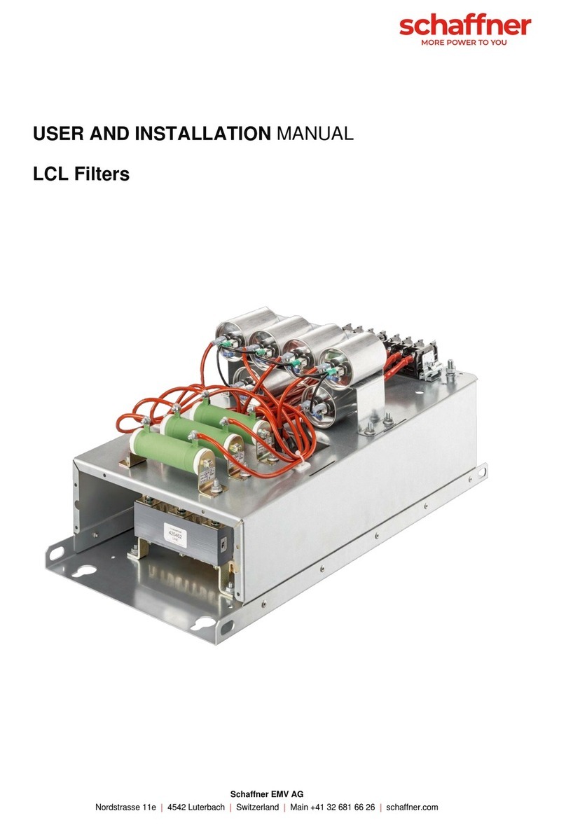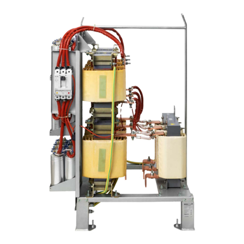
Schaffner Group
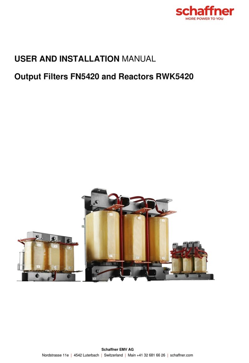
User and Installation Manual
Output filter FN5420 and RWK5420
schaffner.com 6/52
Content
1Sine wave filter FN5420 designation..................................................................8
1.1 Sine wave filter designation ...................................................................................................... 8
1.1.1 Example of sine wave filter designations .............................................................................. 8
1.2 Dv/dt reactor designation .......................................................................................................... 9
1.2.1Example of sine wave filter designations .............................................................................. 9
1.3 Additional Resources................................................................................................................. 9
1.4 Naming convention .................................................................................................................... 9
2Filter selection ...................................................................................................10
2.1 Filter selection table FN5420 IP00........................................................................................... 13
2.2 Filter selection table FN5420 IP20........................................................................................... 14
2.3 Filter selection table RWK5420 ............................................................................................... 15
2.4 Derating ..................................................................................................................................... 16
2.4.1 Temperature derating.......................................................................................................... 16
2.4.2 Motor frequency derating..................................................................................................... 17
2.4.3 Calculation example of derating.......................................................................................... 17
3Filter description................................................................................................18
3.1 General electrical specifications FN5420............................................................................... 18
3.2 General electrical specifications RWK5420........................................................................... 19
3.3 Power losses............................................................................................................................. 20
3.3.1 Power loss calculation example .......................................................................................... 20
3.4 Additional electrical specifications ........................................................................................ 21
3.5 Screw size, torque and cable cross-section requirement.................................................... 22
3.5.1 Power terminals................................................................................................................... 22
3.5.2 Auxiliary signal and earth terminals..................................................................................... 24
3.6 Thermal protection switch specifications.............................................................................. 25
3.7 Cooling requirement................................................................................................................. 25
3.8 Mechanical data........................................................................................................................ 26
