BBV BBV RX100 User manual

Building Block Video Ltd.,
17 Apex Park,
Diplocks Industrial Estate,
Hailsham, East Sussex, BN27 3JU, UK.
Tel:+44 (0)1323 842727
Fax:+44 (0)1323 842728
Support:+44(0)1323 444600
www.bbvcctv.com
Telemetry
Interface
Installation
Guide
BBVBBV
Model covered
Rx100
Dome interface Rx100
Dome Interface

Installation Manual – Rx100 Interface Edition 1.5 March 2001 Page 2
TABLE OF CONTENTS
1. Pre-installation Checks and Safety Procedures 3
Unpacking 3
Important safety precautions 3
2. Introduction 5
General 5
Rx100 Technical specification 5
Transmitter compatibility chart 6
Cable connection method 7
Fig. 1 Wago cable connectors
Cable types 7
3. Installation 8
Operating voltage 8
Rx100 connections 8
Fig. 2 Rx100 pcb connections
4. Setup 9
Diagnostic aids 9
Cable length compensation 9
Fig. 3 Launch amplifier
5. System schematic diagrams 10
Fig. 4 Integration of dome into conventional system
Fig. 5 Simple single camera system
Appendix A - Dome Connection Details A-1
Appendix B - Troubleshooting B-1

Installation Manual – Rx100 Interface Edition 1.5 March 2001 Page 3
1. PRE-INSTALLATION CHECKS AND SAFETY PROCEDURES
UNPACKING
Check Packaging - Upon taking delivery of the unit, inspect the packaging for signs of damage. If
damage has occurred, advise the carriers and/or the suppliers immediately.
Check Contents - Upon taking delivery of the unit, unpack the unit carefully and check that all the
items are present and correct. If any items are missing or damaged, contact your equipment dealer.
Retain Packaging - The shipping carton is the safest container in which to transport the unit.
Retain undamaged packaging for possible future use.
IMPORTANT SAFETY PRECAUTIONS
Read Instructions - All relevant safety, installation and operating instructions should be read before
attempting to install, connect or operate the unit.
Retain Instructions - All safety, installation and operating instructions should be retained for future
reference.
Heed Warnings - All warnings on the unit and in any relevant safety, installation or operating
instructions should be adhered to.
Cleaning - Unplug the unit from the power outlet before cleaning. Do not use liquid cleaners or
aerosol cleaners. Use a damp cloth for cleaning.
Attachments - Do not use attachments not recommended by the product manufacturer as they may
cause hazards.
Water and Moisture - Do not expose the internal electronics of this unit to water or dampness; for
example, in an unprotected outdoor installation, or in any area classified as a wet location. The unit
as supplied conforms to ingress protection rating IP 67. This rating will be affected by any holes
made in the enclosure. Cable entry points should be protected by the use of suitably rated glands
and/or flexible conduit. It is not necessary to make further holes in the enclosure for mounting
purposes, as mounting holes are provided at the corners of the enclosure outboard of the seal
between enclosure and lid.
Accessories - Do not attach this unit to an unstable stand, bracket or mount. The unit may fall,
causing serious injury to a person and serious damage to the unit.
Power Sources - This unit should be operated only from the type of power source indicated on the
manufacturer’s label. If you are not sure of the type of power supply you intend to use, consult your
equipment dealer or local power company. For units intended to operate from battery power or
other sources, refer to operating instructions.
Power Connector - This unit is equipped with coaxial power connector mounted at the edge of the
PCB for low voltage power input. Do not attempt to alter this connector in any way.
Power Cord Protection - Power supply cords should be routed so that they are not likely to be
trapped, pinched or otherwise damaged by items in close proximity to them, whether inside the unit
or outside it. Particular attention should be paid to cords at plugs, connection units and the point of
exit from the unit.
Overloading - Do not overload outlets and extension cords, as this can result in fire or electric
shock.
Object and Liquid Entry - Never push objects of any kind into the unit, as they may touch
dangerous voltage points or short out parts that could result in fire or electric shock. Never spill
liquid of any kind on or inside the unit.
Servicing - Servicing of the unit should only be undertaken by qualified service personnel, as
opening or
removing covers may expose you to dangerous voltages or other hazards.

Installation Manual – Rx100 Interface Edition 1.5 March 2001 Page 4
Damage Requiring Service - Servicing by qualified personnel should be carried out under the
following conditions:
(a) When the power-supply cord or plug is damaged;
(b) If liquid has been spilled, or objects have fallen into, the unit;
(c) If the internal electronics of the unit have been exposed to rain or water;
(d) If the unit does not operate normally by following the operating instructions. Adjust only
those controls that are covered by the operating instructions, as improper adjustment of
other controls may result in damage and will often require extensive work by a qualified
technician to restore the unit to normal operation;
(e) If the unit has been dropped or the enclosure is damaged;
(f) If the unit exhibits a distinct change in performance. This indicates a need for service.
Replacement Parts - If replacement parts are required, ensure that only replacement parts
recommended by the product manufacturer are used.
Safety Check - Upon completion of any service or repairs to the unit, safety checks should be
performed to ensure that the unit is in proper operating condition.
Pre-installation Checks - It is recommended that the unit be bench-tested prior to installation on
the site.
Safety During Installation or Servicing - Particular care should be taken to isolate the dome in
order to prevent operation while engineering work is being carried out on the Rx100.
Adhere to Safety Standards - All normal safety precautions as laid down by British Standards and
the Health and Safety at Work Act should be observed.
WARNING
TO PREVENT DANGER OF FIRE OR SHOCK, DO NOT EXPOSE THE INTERNAL
COMPONENTS OF THIS EQUIPMENT TO RAIN OR MOISTURE.
The “lightning flash with arrowhead” symbol inside an equilateral triangle is used to warn the user of
this equipment that there are sufficiently high voltages within the enclosure to constitute a risk of
electric shock.
The “exclamation point” symbol inside an equilateral triangle is used to alert the user of this
equipment to important operating and maintenance (servicing) instructions in the literature
accompanying the appliance.

Installation Manual – Rx100 Interface Edition 1.5 March 2001 Page 5
2. INTRODUCTION
GENERAL
The Rx100 telemetry interface is designed to allow control of a variety of integrated dome cameras
using BBV’s range of up-the-coax telemetry transmitters. See appendix A for a complete list of
supported domes.
The Rx100 interface is supplied in an IP 67 rated enclosure. It will be necessary to make suitable
holes in the enclosure to permit cable entry and exit. Adequately rated cable glands and or flexible
conduit should be used at all times to avoid compromising the protection afforded by the enclosure
as supplied. Any holes made in the enclosure for any other purpose should be sealed with a non-
hardening water-proof sealant, taking care to ensure that the internal electronics are not
contaminated.
Rx100 TECHNICAL SPECIFICATION
Power Requirements: 9-12V ac/dc – plug mounted PSU provided.
Current Consumption:100mA maximum
Features: •Serial data output either RS232, RS485, RS422.
•4 alarm inputs.
•1 N/C alarm output.
•Up to 16 pre-set positions can be stored within the Rx100.
•Relay capable of switching 1Kw of lighting.
Engineering Facilities:•Unit auto-tunes to the coaxial telemetry signal.
•LED readout for continual system status.
•Video launch amplifier provided with Gain and Lift controls.
•Colour-coded cage clamp terminals. Mains terminal connections: Live,
Neutral and Earth and Low Voltage.
Telemetry Signals: Telemetry signals either:
•up-the-coax (designed to operate over 500m of RG59 coax).
•or twisted pair 0-20mA current loop.
Video Input: 1v p-p 75Ωterminated input via BNC socket.
Video Output: 1v p-p to 4v p-p 75Ωimpedance via BNC socket.
Up to 16 full-scene preset positions can be stored within the interface depending upon the model of
dome.
Dimensions (external):Width: 190 mm
Length: 280 mm
Height: 130 mm
Weight: 1.0Kg
Temperature range: -10° Celsius to +40° Celsius

Installation Manual – Rx100 Interface Edition 1.5 March 2001 Page 6
TRANSMITTER COMPATABILITY CHART
Tx300 Tx400 Tx400DC Tx500 Tx1000 Tx1000D
CDome
Variable
Speed 2Speeds 2Speeds Proportion
al
Joystick
2Speeds 2Speeds Proportion
al
Joystick
ABCDE
F
Fixed
Speed ü ü ü ü ü ü DG
Zoom ü ü ü ü ü ü ALL
Focus ü ü ü ü ü ü ALL
Iris ü ü ü ü ü ü CDEF
Pre-sets -8 8 8 16 16 ABCEF
G
Patrols -2 2 2 2 2 ABCEF
G
Lights ü ü ü ü ü ü ALL
Autopan -ü ü ü ü ü G
Camera
Function
s-ü ü ü ü ü ABEFG
Notes:
Alltec Apollo:
Full access to the camera’s menu is provided.
JVC TK-C675E:
Shutter speeds and alternate Backlight zones can be accessed.
Pelco SD-5:
‘Turbo’ pan/tilt mode can be used by adding option link to J6. This mode is always used when driving to a pre-set
position. Dome Aux. 2 output can be switched using the WASH feature available on
Tx400/Tx400DC/Tx500/Tx1000/Tx1000DC transmitters. Full dome menu accessible: Tx400/400DC ‘#’-‘1’,
Tx500/Tx1000/1000DC ‘#’ – ‘WASH’.
Star MD-100:
The dome provides an autopan feature between pre-set positions 7 & 8 which can be initiated using AUTOPAN on
transmitter. Pan/Tilt speed fixed at 18º/second and 90º/second whilst moving to pre-set position.
May 1998
The Panasonic WV-CSR600B dome now fully supported allowing smooth
variable speed control along with access to the dome's camera setup
menu.
AAlltec Apollo
BJVC TK-C675E
CMark Mercer D250MPT
DPanasonic WV-CSR400/B
EPanasonic WV-CSR600/B
FPelco SD-5 ‘Spectra’
GStar MD-100

Installation Manual – Rx100 Interface Edition 1.5 March 2001 Page 7
CABLE CONNECTION METHOD
Fig. 1: Wago connectors
The WAGO PCB terminal block is a simple-to-use method of
attaching cables to PCBs quickly and easily. Prepare cables
as follows:
•Use only cable between 0.08 and 2.5 mm²
•Strip the cable to a length of 5 to 6 mm (0.23 in)
The correct method of attachment is as follows:
1. Press down the relevant terminal block lever with a
suitable screwdriver;
2. Insert wire;
3. Remove screwdriver.
The procedure for detaching wires is the reverse of the 3
attachment steps, ensuring that power is disconnected
before starting.
CABLING RECOMMENDATIONS FOR THE Rx100 INTERFACE.
Although BBV do not specify any particular type, manufacturer or supplier of cables, the following
ESD Electronic Services (01279 626777) cables have been used successfully for production and
testing:
ESD Part Number: Description:
0222586G Co-Ax Cable (Minimum Specification)
(100 m) RG59B/U ESD radio frequency coax cable to BS2316 and MIL-C-17
1/0.58mm copper-covered steel wire conductor with solid polythene
dielectric, bare copper wire braid and PVC sheath
Characteristic impedance: 75 Ohm
Capacitance: 22pF/ft
020966D Orange-Coloured Lighting Output Power Cable (1000 w)
(100 m) 3183Y PVC-insulated, 3-core cable
1.25mm²40/0.2mm annealed copper conductor
Current rating: 13 amp
0140467H 20mA Twisted Pair Cable (Minimum Specification)
(100 m) British Telecom spec CW 1308
2-core 1/0.5mm PVC-insulated
Maximum conductor resistance at 20 degrees Celsius: 97.8 ohms/km

Installation Manual – Rx100 Interface Edition 1.5 March 2001 Page 8
3. INSTALLATION
OPERATING VOLTAGE
The Rx100 requires all connections to the PCB to be made by the installer, and via terminal blocks
or by plug and socket. These connections are: power in, video in, video out, serial data to dome. In
addition connections for alarm in, alarm out and lights if required are provided. See fig.2 below for
correct connections.
The Rx100 is supplied pre-configured to suit the application for which it is intended, i.e. to control an
integrated dome camera.
Fig. 2 Rx100 PCB connections
Function Connector Type
Power In J12.1mm coaxial
or J3/AC-AC Grey WAGO
Video In CAMERA BNC SOCKET
Video Out TELEMETRY BNC SOCKET
Twisted Pair Telemetry J3/TP-TP Grey WAGO
Serial to dome J3/C1-C4-GND Grey WAGO
or J7 FCC68
Alarm 1 contact in J3/A1-GND Grey WAGO (optional if alarm input required)
Alarm 2 contact in J3/A2-GND Grey WAGO (optional if alarm input required)
Alarm 3 contact in J3/A3-GND Grey WAGO (optional if alarm input required)
Alarm 4 contact in J3/A4-GND Grey WAGO (optional if alarm input required)
Alarm contact out J3/AOUT-AOUT Grey WAGO (optional if alarm input required)
Lighting relay J5 Coloured WAGO (optional if lighting control
required)
(clean contact between orange connectors)
CABLE
ERROR
BBV
J1
RY1
8 Amp 250V
AC MAX J5
TELEMETRY
CAMERA
GAIN
LIFT
J6/1-2
J3
AC
AC
TP
TP
GND
C1
C2
C3
C4
GND
AOUT
AOUT
GND
GND
A1
A2
A3
A4
J3
J1
POWER 9 - 12 V AC/DC
100mA MAX
J7
U2
U5
U4
IC1
J6 OPTION LINKS
Video In
from dome
Video Out
to transmitter
SW LIVE EARTH NEUTRAL
Lights Supply
Lights
Feed
Neutral
Earth
Live
9-12V
supply
Population
dependant upon
application.
HF Lift Gain
N/C
Alarm IN
contacts
Twisted Pair IN from
telem transmitter
N/C Alarm
OUT to Tx1000
1
5
J6/4-5
RS485 OUT to dome
Installation Manual – Rx100 Interface Edition 1.5 March 2001 Page 9
4. SETUP
DIAGNOSTIC AIDS
Two L.E.D.s are mounted on-board to give simple system status information. Their functions are as
follows:
Cable LED
Regular Blinking -Telemetry and video signals are OK.
Blinking but mainly ON -No Telemetry from the transmitter.
Blinking but mainly OFF -No video from the camera.
Error LED
On -Telemetry transmission error.
Both LEDs
Off -No power or major PCB fault.
All BBV equipment is designed to auto-tune and compensate for any discrepancies in the
transmitted telemetry signal, there are no further adjustments that need to be made.
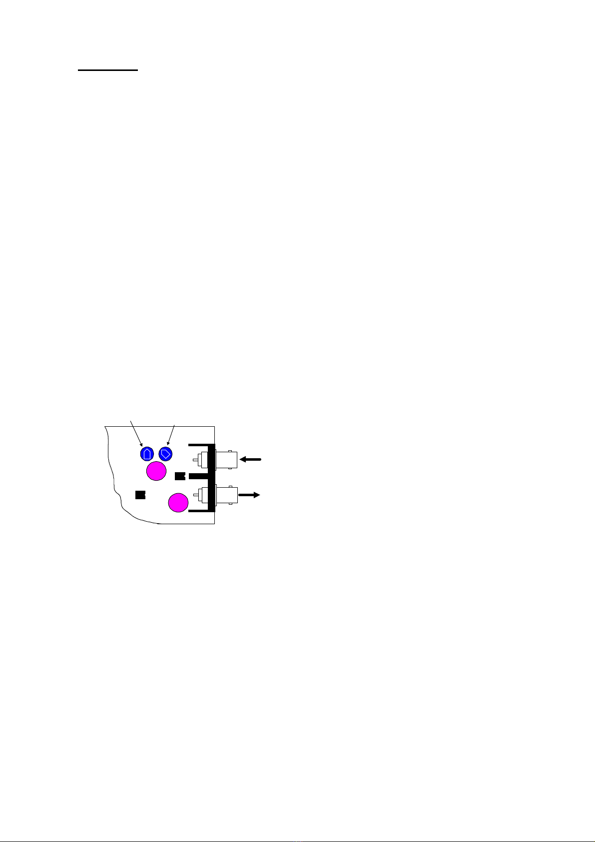
VIDEO LAUNCH AMPLIFIER AND CABLE LENGTH COMPENSATION
The interface features a video launch amplifier with two variable controls situated close to the BNC
connectors: Lift and Gain. These are pre-adjusted for a cable distance of 500m of RG59, are and
adjustable to compensate for video detail or signal losses if and when longer or shorter cable
lengths are used to connect the telemetry transmitter to the interface.
Fig. 3 Launch Amplifier
The purpose of each control is:
GAIN varies the overall signal level.
LIFT boosts the high frequency component of the
video signal. If the high frequency component is too
low, picture appears ‘washed out’ and lacking detail.
Default position adjusted for 500M of RG59.
For shorter cable lenghts, turn the Gain control anti-clockwise until 1V p-p is present at the telemetry
transmitter. For longer cable lengths, turn the Gain control clockwise until 1V p-p is present at the
telemetry transmitter.
TELEMETRY
CAMERA
GAIN
LIFT
Video
from
dome
Video
to
transmitter
HF Lift Gain
Installation Manual – Rx100 Interface Edition 1.5 March 2001 Page 10
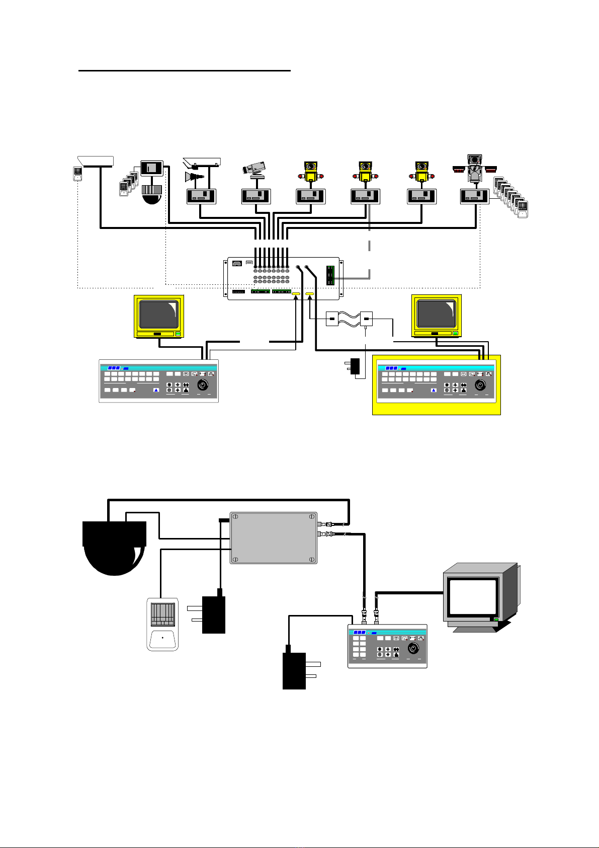
5. SYSTEM SCHEMATIC DIAGRAMS
Fig.4
SYSTEM SCHEMATIC SHOWING INTEGRATION OF DOME INTO CONVENTIONAL SYSTEM.
Fig. 5 SIMPLE SINGLE CAMERA SYSTEM
KEYBOARD 1
Optional Alarm Package
Rx100
dome camera
4 local alarms
STATIC
static camera
Rx200
static camera with lights/
wash/wipe Rx200
simple AC panner
Rx300
AC P/T Zoom/Focus
1 Aux.
Rx400P
AC P/T Zoom/Focus
16 Presets with 3 Aux.
Rx300M
AC P/T Mitsubishi
CCD400 control
2 Aux.
Rx400DC
High & Variable speed
P/T Zoom/Focus
16 Preset with 3 Aux.
8 Local alarms
alarm cable
Optional
Twisted Pair
OPTIONAL 2ND KEYBOARD
B B V
300
LENS
LENS
IRIS FOCUS ZOO
M
PROGRAM
#
AUTOPAN
9 10 11 12 13 14 15 16
875 6431 2
CAMERA SELECT
MONITOR
PAN
+
TILT
PRESETPATROLSEQ
B B V1000
B B V
300
LENS
LENS
IRIS FOCUS ZOO
M
PROGRAM
#
AUTOPAN
9 10 11 12 13 14 15 16
875 6431 2
CAMERA SELECT
MONITOR
PAN
+
TILT
PRESETPATROLSEQ
B B V1000
video in - coax
Tx1000/8 or 16 Base Unit
video out - coax
TxLD TxLD
Twin Twisted Pair
9V plug PSU
Optional TxLD link. Distance > 50M.
up-the-coax telemetry control up to 1Km CT125
Twisted Pair telemetry.
Loop resistance < 300R
RS232 control Max distance - 50M
Optional TxLD available for extended
distances.
BBV
PRESETS
87
5 6
43
1 2
LENS
IRIS FOCUS ZOOM
PROGRAM #
400
AUTOPAN
PAN+ TILT
Rx100 Interface
9V
PSU
9V
PSU
Video
Data
Alarm
contact
Tx400DC
MONITOR

Rx100 manual Appendix A – Dome connections Page A-1
Appendix A - Dome connection details
Alltec Apollo A-2
JVC TK-C675E A-3
Mark Mercer D250MPT A-4
Panasonic WV-CSR400/B A-5
Panasonic WV-CSR600/B A-6 Now Fully supported
Pelco SD-5 ‘Spectra’ A-7
Star MD-100 A-9

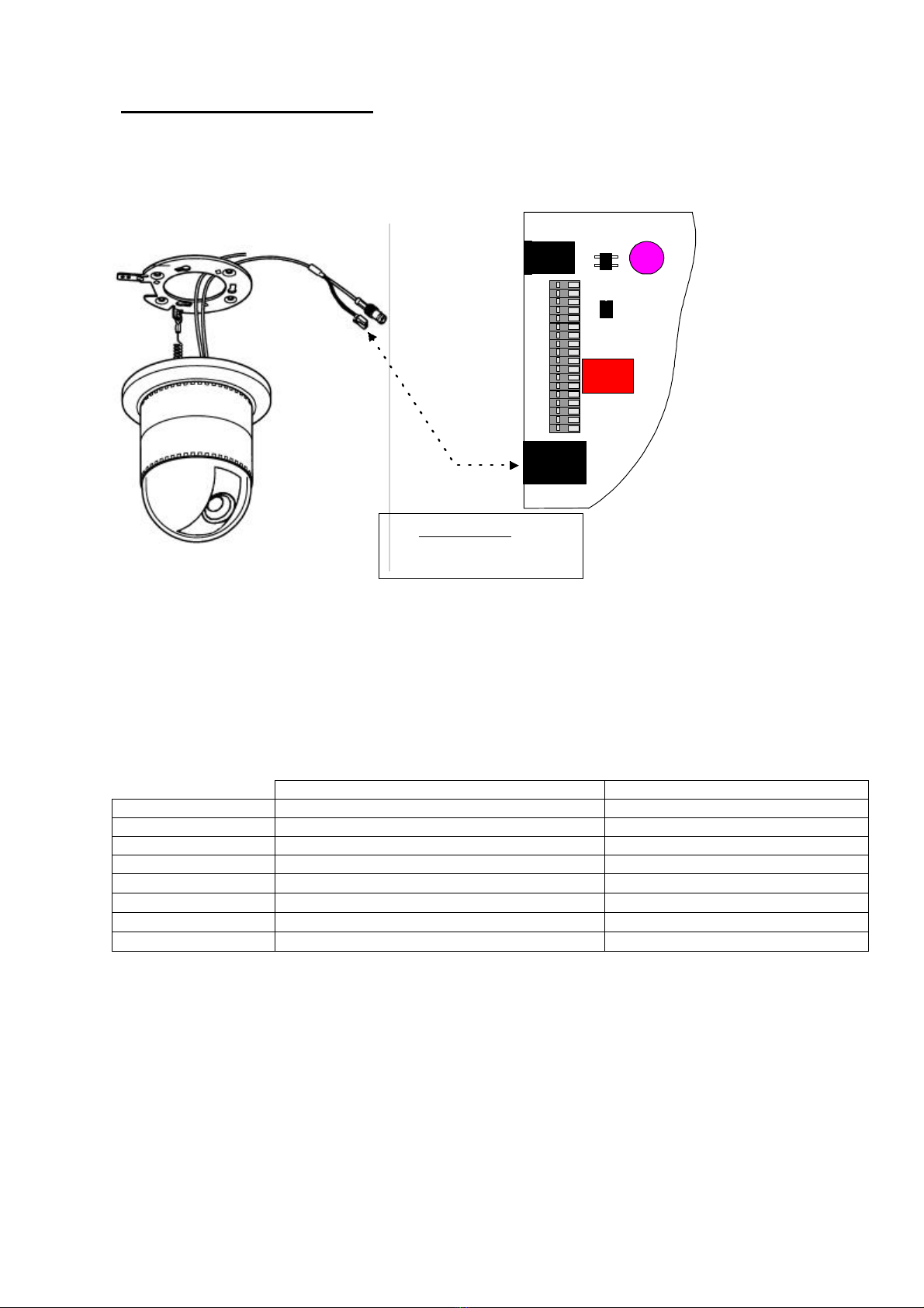
Rx100 manual Appendix A – Dome connections Page A-2
J3
J3
J1
POWER 9 - 12 V AC/DC
100mA MAX
J7
U5
U4
9-12V
supply
AC
AC
TP
TP
GND
C1
C2
C3
C4
GND
AOUT
AOUT
GND
GND
A1
A2
A3
A4
Data connection
Alltec P1(DB9 female) Rx100 J3
Pin 2 C3
Pin 1 GND
To Rx100 'CAMERA' input
Alltec Apollo
The dome must be powered from the power supply packaged with the dome.
Data connection via 2 wire RS232 using DB9-female to connect to P1 on the rear panel of the
dome. The free end connects to J3 of the Rx100.
Video connection BNC plug – BNC plug from dome to ‘CAMERA’ input of Rx100.
COMMISSIONING
Connect dome and Rx100 as shown. Link Rx100 video out to telemetry transmitter using coaxial
cable.
Power up Rx100 first, cable LED should blink.
Next the dome can be powered at which point a self test is performed. The dome will check both
pan and tilt motors, initialise it’s camera and calibrates it’s preset positioning. The dome then resets
the camera resulting in a temporary loss of video. When the video image has reappeared the dome
is ready for operation.
FEATURES
The Rx100 provides the following features.
Tx400DC Tx1000DC
Pan/Tilt Joystick Joystick
Zoom Zoom keys Zoom keys
Focus Focus keys (Holding for 2½
seconds enables auto focus) Focus keys (Holding for 2½
seconds enables auto focus)
Save pre-set Hold PROGRAM &tap 1 - 8 Press PROGRAM then 1then
1-
16
Goto pre-set Tap 1 - 8 Hold PRESET &tap 1 - 16
Start Patrol 1 Hold PROGRAM &
tap
AUTOPAN Hold PATROL &tap 1
Start Patrol 2 Hold PROGRAM &tap LIGHTS Hold PATROL &tap 2
Camera Menu
Commands
Enter/Exit Hold #&tap 1Hold #&tap WASH
UP Menu Hold #&tap 2Hold #&tap WIPE
DOWN Menu Hold #&tap 4Hold #&tap LIGHTS
SET Hold #&tap 3Hold #&tap AUTOPAN
The Camera menu can only be accessed when the OPTION LINK on J6 of the Rx100 is removed.
To prevent the camera from hanging please ensure that you EXIT after using end option in the
camera menu.
It is recommended that the camera menu is not accessed unless conversant with the camera
settings.
Local alarm activation 1-4 will drive dome to pre-set position 1-4 if programmed.

Rx100 manual Appendix A – Dome connections Page A-3
JVC TK-C675E
The dome must be powered from a 24Vac supply.
Data connection via 2 wire RS422 using screw terminals on the dome base plate and J3 on the
Rx100.
Video connection from screw terminals on dome base plate to ‘CAMERA’ BNC socket on the
Rx100.
NOTE:
Ensure that switch on base plate set to RS-422A and that Switches 4 & 5 of DIP switch set as
shown.
COMMISIONING
Connect dome and Rx100 as shown. Link Rx100 video out to telemetry transmitter using coaxial
cable.
Power up Rx100 first, cable LED should blink.
Next dome can be powered at which point a self test is performed. Both pan and tilt are checked.
The dome is ready for operation.
FEATURES
The Rx100 provides the following features.
Tx400DC Tx1000DC
Pan/Tilt Joystick Joystick
Zoom Zoom keys Zoom keys
Focus Focus keys Focus keys
Save pre-set Hold PROGRAM &tap 1 - 8 Press PROGRAM then 1then 1-16
Goto pre-set Tap 1 - 8 Hold PRESET &tap 1 - 16
Start Patrol 1 Hold PROGRAM &tap AUTOPAN Hold PATROL &tap 1
Start Patrol 2 Hold PROGRAM &tap LIGHTS Hold PATROL &tap 2
Camera
Shutter Speed Hold #&tap 1(cycle 1/60,1/100,
1/1000,1/2000,1/10000 sec) Hold #&tap WASH (cycle 1/60,
1/100,1/1000,1/2000,1/10000 sec)
Backlight Zones Hold #&tap 2(cycle Off, Zone
1,Zone 2,Zone 3,Zone 4) Hold #&tap WIPE (cycle Off, Zone 1,Zone
2,Zone 3,Zone 4)
Reset camera
shutter to 1/60 sec
and Backlight off.
Hold #&tap 4Hold #&tap LIGHTS
Local alarm activation 1-4 will drive dome to pre-set position 1-4 if programmed.
J3
J3
J1
POWER 9 - 12 V AC/DC
100mA MAX
J7
U5
U4
9-12V
supply
AC
AC
TP
TP
GND
C1
C2
C3
C4
GND
AOUT
AOUT
GND
GND
A1
A2
A3
A4
Data connection
JVC TK-C675E Rx100 J3
RxC C1
RxH C2
To Rx100 'CAMERA' input
Signal
Ground
RED
GREEN
24Vac
Select RS-422A
0 0
1 6
Switch configuration
side of TK-C 675E

Rx100 manual Appendix A – Dome connections Page A-4
Mark Mercer D250MPT
The dome must be powered from a 120Vac supply.
Data connection via 2 wire RS422 using terminal block from slip rings and J3 on the Rx100.
Video connection from terminal block to ‘CAMERA’ BNC socket on the Rx100.
COMMISSIONING
Connect dome and Rx100 as shown. Link Rx100 video out to telemetry transmitter using coaxial
cable.
Power up Rx100 first, cable LED should blink.
Next, dome can be powered at which point a short self test operation is performed. The dome is
ready for operation shortly after self test.
FEATURES
The Rx100 provides the following features.
Tx400DC Tx1000DC
Pan/Tilt Joystick Joystick
Zoom Zoom keys Zoom keys
Focus Focus keys Focus keys
Iris(when fitted) Iris keys Iris keys
Save pre-set Hold PROGRAM &tap 1 - 8 Press PROGRAM then 1then
1-16
Goto pre-set Tap 1 - 8 Hold PRESET &tap 1 - 16
Start Patrol 1 Hold PROGRAM &
tap
AUTOPAN Hold PATROL &tap 1
Start Patrol 2 Hold PROGRAM &tap LIGHTS Hold PATROL &tap 2
Local alarm activation 1-4 will drive dome to pre-set position 1-4 if programmed.
J3
J3
J1
POWER 9 - 12 V AC/DC
100mA MAX
J7
U5
U4
9-12V
supply
AC
AC
TP
TP
GND
C1
C2
C3
C4
GND
AOUT
AOUT
GND
GND
A1
A2
A3
A4
Data connection
D250 slip ring Rx100 J3
RED C1
GREEN C2
To Rx100
'CAMERA' input
RED
GREEN
YELLOW
ORANGE
Signal
Ground
BROWN
BLACK
120Vac
Supply

Rx100 manual Appendix A – Dome connections Page A-5
Panasonic WV-CSR400B (fixed speed)
The dome requires a 240Vac source.
Data connection using FCC68 modular cable included with dome direct into J7 of Rx100.
Video connection from BNC socket via plug-socket into ‘CAMERA’ socket of Rx100.
COMMISSIONING
Connect dome and Rx100 as shown. Link Rx100 video out to telemetry transmitter using coaxial
cable.
Power up Rx100 first, cable LED should blink.
Next, dome can be powered up and is immediately ready for use.
FEATURES
The Rx100 provides the following features.
Tx400DC Tx1000DC
Pan fixed 24º/sec
Tilt fixed 12º/sec Joystick or Keys if none DC Joystick or Keys if none DC
Zoom Zoom keys Zoom keys
Focus Focus keys Focus keys
Iris Iris keys Iris keys
Local alarm activation 1-4 will trigger alarm. The dome does not have pre-set capability, therefore
head will not move following alarm activation.
J3
J3
J1
POWER 9 - 12 V AC/DC
100mA MAX
J7
U5
U4
9-12V
supply
AC
AC
TP
TP
GND
C1
C2
C3
C4
GND
AOUT
AOUT
GND
GND
A1
A2
A3
A4
240Vac Supply
To Rx100
'CAMERA' input
Data direct into J7
Data connection
Dome cable Direct into J7
Rx100 manual Appendix A – Dome connections Page A-6
Panasonic WV-CSR600B
The dome requires a 240Vac source.
Data connection using FCC68 modular cable included with dome direct into J7 of Rx100.
Video connection from BNC socket via plug-socket into ‘CAMERA’ socket of Rx100.
COMMISSIONING
Connect dome and Rx100 as shown. Link Rx100 video out to telemetry transmitter using coaxial
cable.
Power up Rx100 first, cable LED should blink.
Next, dome can be powered up at which point a self test operation is performed. The dome is ready
for use when test is completed.
FEATURES
The Rx100 provides the following features.
Tx400DC Tx1000DC
Pan/Tilt Joystick Joystick
Zoom Zoom keys Zoom keys
Focus Focus keys Focus keys
Iris(when fitted) Iris keys Iris keys
Save pre-set Hold PROGRAM &tap 1 - 8 Press PROGRAM then 1then 1-16
Goto pre-set Tap 1 - 8 Hold PRESET &tap 1 - 16
Start Patrol 1 Hold PROGRAM &tap AUTOPAN Hold PATROL &tap 1
Start Patrol 2 Hold PROGRAM &tap LIGHTS Hold PATROL &tap 2
Local alarm activation 1-4 will drive dome to pre-set position 1-4 if programmed.
J3
J3
J1
POWER 9 - 12 V AC/DC
100mA MAX
J7
U5
U4
9-12V
supply
AC
AC
TP
TP
GND
C1
C2
C3
C4
GND
AOUT
AOUT
GND
GND
A1
A2
A3
A4
240Vac Supply
To Rx100
'CAMERA' input
Data direct into J7
Data connection
Dome cable Direct into J7
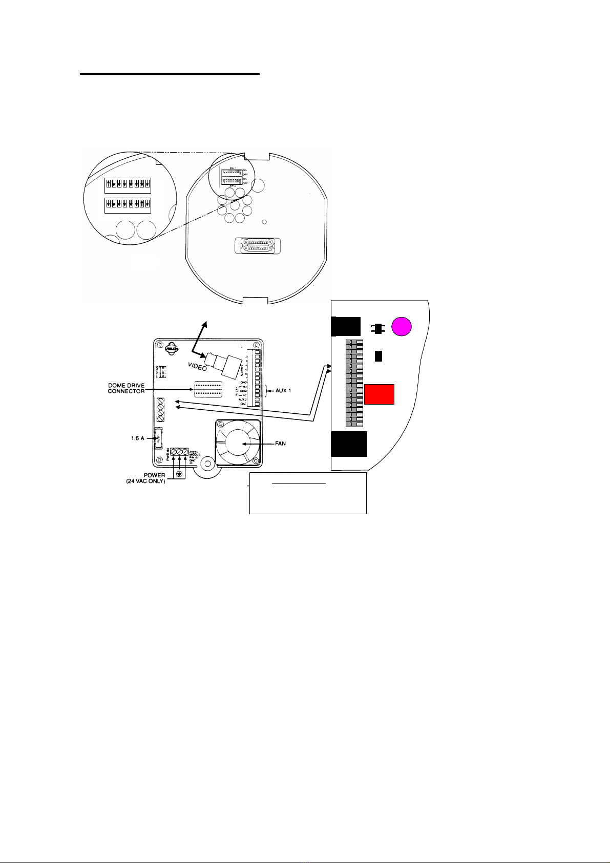
Rx100 manual Appendix A – Dome connections Page A-7
Pelco SD-5 ‘Spectra’ dome
The dome must be powered from a 24Vac supply.
Data connection via 2 wire RS422 using screw terminals on dome back box and J3 on the Rx100.
Video connection from BNC socket on dome back box to ‘CAMERA’ BNC socket on the Rx100.
SET SWITCHES ON BASE OF DOME
AS SHOWN ON THE LEFT.
SW1:1 ON, remainder OFF
SW2:7 ON, remainder OFF
These select P-type control with 9600
baud data rate.
COMMISSIONING
Connect dome and Rx100 as shown. Link Rx100 video out to telemetry transmitter using coaxial
cable.
Power up Rx100 first, cable LED should blink.
Next dome can be powered at which point a self test is performed. On completion of the test, the
dome is ready for operation.
1234 5 67 8
1234 5 67 8
ON
OFF
ON
OFF
SW1 - Select P-type control
SW2 - Address 1,9600 Baud
J3
J3
J1
POWER 9 - 12 V AC/DC
100mA MAX
J7
U5
U4
9-12V
supply
AC
AC
TP
TP
GND
C1
C2
C3
C4
GND
AOUT
AOUT
GND
GND
A1
A2
A3
A4
RX-
RX+
TX-
TX+
To Rx100 - CAMERA
Data connection
Dome Back Box Rx100 J3
RX- C1
RX+ C2

Rx100 manual Appendix A – Dome connections Page A-8
FEATURES
The Rx100 provides the following features.
Tx400DC Tx1000DC
Pan/Tilt Joystick Joystick
Zoom Zoom keys Zoom keys
Focus Focus keys Focus keys
Iris Iris keys Iris keys
Save pre-set Hold PROGRAM &tap 1 - 8 Press PROGRAM then 1then 1-16
Goto pre-set Tap 1 - 8 Hold PRESET &tap 1 - 16
Start Patrol 1 Hold PROGRAM &tap AUTOPAN Hold PATROL &tap 1
Start Patrol 2 Hold PROGRAM &tap LIGHTS Hold PATROL &tap 2
Aux2. Dome
back box
output.
WASH WASH
Dome Menu Hold #& tap 1Hold #& tap WASH
Note: Very high speed, ‘Turbo mode’ can be enabled when joystick moved to limits by fitting the
OPTION LINK to J6 of Rx100. If the link is removed then standard speeds will be used. Turbo
mode speed is used when responding to an alarm activation.
Local alarm activation 1-4 will drive dome to pre-set position 1-4 if programmed.
Note:
The dome menu is accessed by using the keystrokes shown in the above table. This key sequence
sends a ‘Program Preset 95’ command to the dome which is a special function. The exact menu
structure is explained in the SD5 Installation/Operation Manual.
As an example, the following keystrokes are used to set the maximum zoom ratio to 48. The
example assumes that a Tx1000 is controlling the Rx100. Please use the keystrokes corresponding
to the Tx400dc if that unit is controlling the Rx100.
1. Select the camera to be programmed.
2. Hold #& tap WASH. The display shows: ðð<Camera>
<Line Sync>
<Other>
Exit
3. Press ‘IRIS OPEN’. The ðchanges to -indicating that this function is selected.
Hold #& tap WASH
4. The Camera menu is now displayed: ððBacklight comp Off
Zoom limit x96
Reset camera
<Gain/AGC>
<Auto iris>
Next
Exit
5. The ðcan be moved up & down by either pressing the tilt up & down keys or
moving the joystick up and down. When the ðis beside the Zoom limit line, press
‘IRIS OPEN’, the ðwill change to -indicating that this function is selected. Hold #
& tap WASH.
6. The Zoom limit line now shows: -Zoom limit ððx96. The zoom ratio can be
changed by either pressing the up and down keys or moving the joystick up and
down. When the correct value is displayed press ‘OPEN IRIS’ to select this value.
Hold #& tap WASH.
7. To exit from the menu, move the ðdown to Exit and press ‘OPEN IRIS’ and then
Hold #& tap WASH.
8. Repeat step 7 to exit completely and return to normal operation.
Please refer to the Pelco documentation for a complete description of available menu settings.
The above function is available with Rx100 software Revision 2 and later. Please contact BBV for a
software upgrade if required.

Rx100 manual Appendix A – Dome connections Page A-9
STAR MD-100
The dome must be powered from a 12Vdc supply.
Data connection via 3 wire RS422 using DB9 female to supplied dome cable and J3 on the Rx100.
Video connection from BNC socket on dome base to ‘CAMERA’ BNC socket on the Rx100.
NOTE:
Ensure that all switches on DIP switch set to OFF.
COMMISIONING
Connect dome and Rx100 as shown. Link Rx100 video out to telemetry transmitter using coaxial
cable.
Power up Rx100 first, cable LED should blink.
Next dome can be powered at which point a self test is performed. Both pan and tilt are checked.
The dome is ready for operation.
FEATURES
The Rx100 provides the following features.
Tx400DC Tx1000DC
Pan/Tilt
18º/Sec Joystick Joystick
Zoom Zoom keys Zoom keys
Focus Focus keys Focus keys
Save pre-set Hold PROGRAM &tap 1 - 8 Press PROGRAM then 1then 1-16
Goto pre-set Tap 1 - 8 Hold PRESET &tap 1 - 16
Start Patrol 1 Hold PROGRAM &tap AUTOPAN Hold PATROL &tap 1
Start Patrol 2 Hold PROGRAM &tap LIGHTS Hold PATROL &tap 2
Autopan
between
preset 7 & 8
Tap AUTOPAN after programming preset
positions 7 & 8. Tap AUTOPAN after programming preset
positions 7 & 8.
Camera
Shutter Hold #&tap 1
(toggle Fixed/Auto) Hold #&tap WASH
(toggle Fixed/Auto)
Local alarm activation 1-4 will drive dome @ 90º/Sec to pre-set position 1-4 if programmed.
J3
J3
J1
POWER 9 - 12 V AC/DC
100mA MAX
J7
U5
U4
9-12V
supply
AC
AC
TP
TP
GND
C1
C2
C3
C4
GND
AOUT
AOUT
GND
GND
A1
A2
A3
A4
To Rx100 - CAMERA
DB9 female
Data connection
DB9 Female Rx100 J3
4RD(-) C1
3RD(+) C2
5GND GND
12Vdc
Power
Supply

Rx100 manual Appendix B – Trouble Shooting Page B-1
Appendix B - Trouble shooting guide.
Symptom: No video from interface.
Possible causes:
1. Camera is not powered or not connected to ‘CAMERA’ BNC on interface.
Check power and cabling.
2. Interface is not powered.
Check power.
3. Video out not connected to ‘TELEMETRY’ BNC on interface.
Check cabling.
If the after following the above check list video still not present then remove both BNCs from the
interface and connect together using a female/female barrel connector to check video path from
camera to control point.
Symptom: No camera control but lights relay operates with LIGHTS key on transmitter.
Possible causes:
1. Dome data cable is not connected correctly.
Check cabling, most commonly due to data cables swapped.
2. Dome configuration switches if fitted not set correctly.
Check configuration.
Symptom: No camera control and lights relay not operating.
Possible causes:
1. Interface not seeing Telemetry signal.
Check that telemetry is present on video cable using either oscilloscope or adjust v.hold on
monitor to view frame blanking period and check for black/white band. If missing, power
down/up the transmitter. Should this fail, swap video between working and non working
channels.
2. Earth loops can interrupt telemetry operation if sufficiently severe.
If hum bars are apparent, fit isolation transformer to coaxial cable.
3. Check cable and error LEDs on interface.
See SETUP section earlier in this manual for correct indication.
If the problem persists having followed the above steps, technical assistance can be received from
Building Block Video. Tel: +44 (0)1323 444600
Other manuals for BBV RX100
1
Table of contents
Other BBV Recording Equipment manuals


