RFID 2022 User manual

INSTALLATION AND OPERATING
MANUAL
FOR
SERIAL MULTIPLEX INTERFACE
MODEL 2022 Part No. 710-0018-00
MODEL 2022E Part No. 800-0070-00
Version 4.04 (year/month)

2
TABLE OF CONTENTS
SECTION 1 -GENERAL INFORMATION
1.1 INTRODUCTION Page 3
1.2 DESCRIPTION Page 3
1.3 SPECIFICATIONS Page 4
SECTION 2 -INSTALLATION
2.1 INTRODUCTION Page 5
2.2 UNPACKING AND INSPECTION Page 5
2.3 PREPARING FOR INSTALLATION Page 5
2.4 POWER REQUIREMENTS Page 5
2.5 POWER CONNECTIONS Page 8
2.6 READER WIRING Page 9
2.7 READER CONNECTIONS Page 10
2.8 ABOUT ENABLE & ENABLE REMOTE Page 10
2.9 ABOUT SHIELDING Page 11
2.10 MATING THE INTERFACE TO A COMPUTER Page 11
2.10.1 SETTING SERIAL TYPE Page 11
2.10.2 ASCII FORMAT Page 12
2.10.3 DATA TRANSFER RATES, BAUD Page 13
2.10.4 SERIAL CABLING Page 13
2.10.5 SERIAL CONNECTION Page 14
2.11 DEFAULT OPERATING MODE Page 15
2.12 AUXILORY PORT FOR LCD Page 15
2.13 INSTALLATION COMPLETE Page 15
SECTION 3 -OPERATION
3.1 INTRODUCTION Page 16
3.2 THEORY OF OPERATION Page 16
3.3 TIMING Page 17
3.3.1 WORSE CASE TAG REPORT TIMING Page 17
3.3.2 TIMING SUMMARY Page 19
3.4 DATA PROTOCOL Page 20
3.5 ISSUING COMMANDS TO THE INTERFACE Page 20
3.6 INTERFACE RESPONSES Page 25
3.6.1 TAG DATA Page 25
3.6.2 ERROR MESSAGES Page 26
3.7 WARRANTY Page 27
If you are reading a pdf version of this manual you may notice page numbers and the above contents to
be off by a page from time to time. The conversion to Acrobat has a tendency to move sections as the
fonts don’t translate perfectly.

3
SECTION 1
GENERAL INFORMATION
1.1 INTRODUCTION
This manual provides information pertaining to the installation and operation of the Model 2022
Interface (RFID, Inc. Part No. 710-0018-00), or Model 2022E (the E signifying enclosure) (RFID,
Inc. Part No. 800-0070-00).
1.2 DESCRIPTION
The Interface Model 2022 is termed Multiplex because it can manage up to 16 addressable Readers
and Antennas using time division multiplexing. The Interface Model 2002 provides a full-duplex,
asynchronous bit serial data stream which will interface to various equipment compatible with
RS-232-C,RS-422-A, or RS-423-A specifications. The Interface is configured as Data Terminal
Equipment (DTE).
The 2022 detects, filters and amplifies the data signals relayed by any of the compatible Readers
(Models 1845 and 1885) and converts that data into a serial string. Basically, the Interface provides
RF to digital translation of the signal produced by RFID, Inc. RF Electronic Labels, which are referred
to as "Tags", when placed in the proximity of a Reader/Antenna. Advanced error detection algorithms
provide error-free operation. All messages are transmitted in printable ASCII characters in
transmit-on-receipt or polled mode.
The Interface provides on its ENABLE outputs, pulses that control the operation of Addressable
Readers. In normal operation the Interface produces a pulse to disable all connected Readers, then
follows that with pulses that enable each Reader one at a time. During the brief period that each Reader
is enabled, the SIGNAL inputs are monitored for the presence of a Tag, and if detected, that Tag's
contents are reported along with a hexadecimal channel number identifying the Reader at which the Tag
was detected.
Via the serial connection, over which Tags are reported, the Interface can also be commanded to buffer
Tags, report multiple Tag readings, repeat the last message, test itself, reset, or delete specified Readers
from its polling loop.
The Eurocard format paired with the single supply voltage requirement simplify its integration into
existing installations. Connection to the Reader is made using low-cost shielded twisted pair cables and
angle entry terminals simplify installation.

4
1.3 SPECIFICATIONS
Protocol: Full-duplex, RS232/423 or RS422
Selectable stop bits, parity sense, and word length
Serial Data Rate: Selectable baud rate, 110, 300, 600, 1200, 2400, 4800, 9600, 19200
Control Signals: DSR, CTS, DTR
Processing Speed: Up to 20 Readings/second
Data Storage: 2 Readings
Error Rate: Less than 1 in 10 to the 14th readings
Connectors
Serial: DB-25S
Power: 64-pin DIN 41612 Type C
Readers: 5 position screw type terminal strip
Multiplex Control: 2-wire, Multi-drop scheme, 48mA, max.
Input: 75 Ohms, Balanced, Multi-drop
Cabling Distance
to Readers: Up to 5000 feet, total (with shielded twisted pair cable)
Power Requirements: +5 Volts DC, +/-5% @ 350 mA. (max.) 250 mA. (typ.)
Temperature Range
Operating: -40 to +70 degrees C
Non-operating: -55 to +85 degrees C
Dimensions:
Model 2022: 7.0" x 3.9" x 6.6"
Model 2022E: 9.0" x 5.1" x 1.7"
Weight
Model 2022: 5.5 oz.
Model 2022E: 1.24 lbs (.56kg)

5
SECTION 2
INSTALLATION
2.1 INTRODUCTION
This section contains information for unpacking, installing, and configuring the Interface, including power,
signal, and enable wiring, and rating power supplies. Installation also includes matching and connecting
the Interface to the Host Computer or Terminal.
2.2 UNPACKING AND INSPECTION
If the shipping carton is damaged or shows evidence of abusive handling, inspect the Interface for visible
damage including dents, scratches, etc. If the unit appears damaged, contact the carrier and RFID, Inc.
Sales or Customer Service Departments immediately. Keep the shipping and packaging material for the
carrier's inspection. RFID, Inc. will arrange for repair or replacement of the damaged unit without
waiting for the claim settlement with the carrier.
2.3 PREPARING FOR INSTALLATION
The power is provided through the Eurocard connector 64 pin DIN and signal connections are made
via a terminal strip on the printed circuit board. If the RFID, Inc. enclosure assembly is not provided for
the Eurocard, you must provide a Eurocard DIN connection with +5v on pins a1,c1, and ground on
pins a32, c32. To access the inside of the Model 2022E assembly, remove the end plates and remove
the printed circuit board assembly. The end plates may be removed by first removing the four corner
hex nuts on each end plate which secure it to the assembly. Refer to the Figure 2-1.
Following installation of all Reader wiring, the end plates should be reinstalled using the same screws.
The cable gland should be tightened to secure and seal the wiring.
2.4 POWER REQUIREMENTS
The Interface must be powered from a regulated power source (linear supplies are acceptable,
switching supplies are out of the question) having the following characteristics:
Voltage DC Voltage Range: 4.75 to 5.25 volts
Ripple: 100 mV p-p (max.)
Current Operating: 350 mA. (max.)
100 mA. (typ.)
RFID, Inc. can provide a power supply suitable for use with the Model 2022. The Interface should be
operated from a grounded supply that has the same ground reference as the host computer. The ground
reference used for the Readers may be of a different origin.

6

7

8
2.5 POWER CONNECTIONS
On the Model 2022E, power wiring is already threaded through the cable gland and connected to the
solder tail DIN connector (P1) on the circuit card. There should be a knot in the wire to provide strain
relief. Wires should be connected in accordance with the following:
TABLE 2-1 POWER CONNECTIONS
DIN Connector (P1) CONNECTION
PIN NUMBER FROM DC SOURCE
a1,c1 +5v
a32,c32 DC Return (GND)
WARNING
The power source should be turned off while making connections to the reader. It is
recommended that the power source remain off anytime the circuit board is removed from its
enclosure assembly.
Power connection to the Interface should be made with the power source turned off. There is no
onboard over current protection so an external fuse is recommended to protect the power supply if it
has no over current protection of its own.
If the Interface is to be used without an enclosure, these mating DIN connectors are recommended for
connection of the power wires:
Panduit 100-964-454
Elco 208457096008026
Weidmuller 914605
If the Interface is to be housed in a backplane, make sure that pins a,c2 -a,c31 are left unconnected.
These pins are connections to the processor's data bus and can affect the Interface's operation if
improperly connected.
A note about power cable length: Long power cables will produce voltage drops resulting in a lower
voltage at the Interface end than at the power supply end. There is no inherent limit to the length of wire
from the supply to the Interface as long as the high and low voltage specifications are maintained at the
Interface.

9
2.6 READER WIRING
This section describes the signal and enable wiring that connects the Interface to the Readers. The two
SIGNAL wires provide the path for RF data from the Readers into the Interface. The two ENABLE
wires provide multiplex control from the Interface to the Readers. Shielded, #14 to #28 AWG,
insulated, stranded wire is recommended and all wires should be stripped approximately 3/8 inch and
tinned. The following cables are recommended:
TABLE 2-2 RECOMMENDED CABLES
APPLICATION CABLE DESCRIPTION RECOMMENDED TYPE
Signal Only Cable, Paired, 2 Conductor RFID 214-2202-00 or
#22 AWG with foil shield Columbia C2514
Enable Only Polyethylene & PVC, 60 Deg C Manhattan M13226
Belden 8761
Signal Cable, Paired, 4 Conductor RFID 214-2204-00
and #22 AWG (1 Pr.) with foil shield Alpha 2464
Enable #22 AWG (1 Pr.) unshielded Manhattan M4451
Polypropylene & PVC, 60Deg C Belden 8724
Signal and Cable, Paired, 6 Conductor RFID 214-2206-00
Enable and #24 AWG (2 Pr.) with foil shield Manhattan M14477
Power 22 AWG (1 Pr.) unshielded Belden 8786
PVC, 80 Deg C
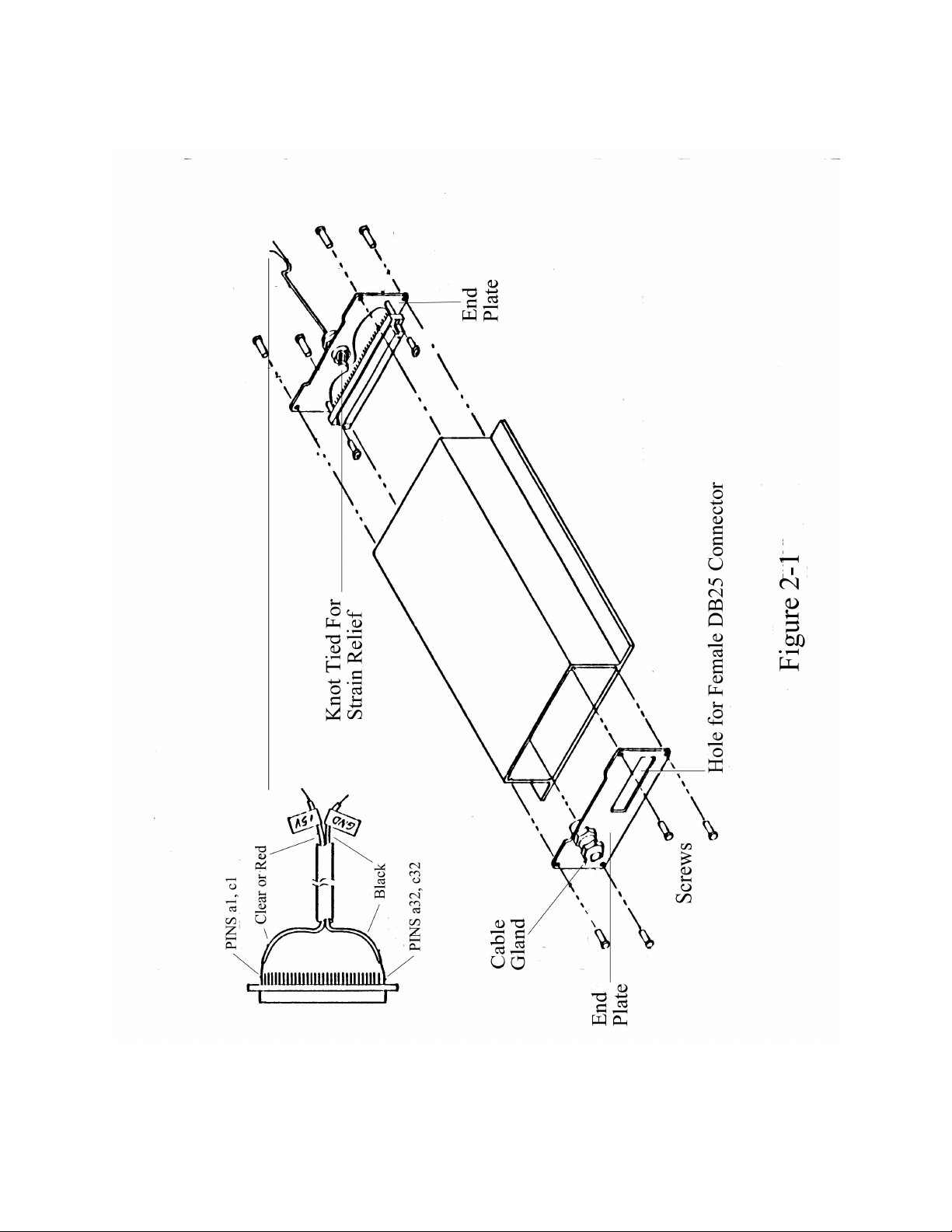
Whatever cable is selected should fit within the range allowed by the cable gland providing wire access
to the reader. The cable gland will accommodate diameters of .090 to .265 inches.
A note about "PLENUM" cabling, plenum cable eliminates the need for using conduit when installing
cables in air plenums. In typical modern buildings, a plenum exists between the drop ceilings and the
floors that support them. Because these air ducts often run across an entire story they can be a
convenient place to run cable, but they can also be an invitation to disaster if fire breaks out. Fire and
smoke can spread rapidly throughout the air duct system if the fire is able to feed on combustible
materials. The cables designated Plenum are approved by the NEC and UL because of their
flame-resistant and low smoke emission properties. While Plenum cable costs more than conventional
cable, the overall installed cost is generally less because it eliminates the need for conduit installation.
PLENUM
Cable, Paired, 2 Conductor Belden 89182
#22 AWG with foil shield
NEC 725, Class 2 classified

10
2.7 READER CONNECTIONS
On the Model 2022E, wiring should be fed through the cable gland and connected to the angle entry
terminal strip (TB1) on the circuit card. Wiring should be connected in accordance with the following:
TABLE 2-3 READER CONNECTIONS
TERMINAL STRIP (TB1) NOMENCLATURE CONNECTION
1 SIG SIG on Reader
2 SIG SIG on Reader
3 SHD NO CONNECTION IF
CONNECTED ON
READER
4 EN EN on Reader
5 EN EN on Reader
2.8 ABOUT ENABLE AND REMOTE ENABLE
The Reader operation may be controlled (enabled, disabled) from the Interface via the enable outputs
(EN, EN) to the Reader. This is termed remote enable. Alternatively, a shorting jumper or shunt may
be placed across J1 on the circuit board of the Reader assembly. The shunt overrides the remote
enable control and continuously enables the Reader. This feature is maintained primarily for us, the
manufacturer as a testing and quality control tool. It is not recommended for use outside of testing the
Reader. The Reader is not normally supplied with the shorting shunt installed on J1. Refer to your
Reader manual for specific instructions. The typical circuit connection for the remote enable feature is
shown below.

11
2.9 ABOUT SHIELDING
Shielding is recommended for both signal and enable wiring especially if long lengths of wire are used, or
when operating in an environment of high electromagnetic noise. Each wire's shield should be
connected at only 1 point, connecting both ends of a shield will produce a closed loop in which noise
has no way to exit. A daisy chain connecting multiple Readers counts as a single wire, and the shields
should be connected together, but not to the Reader, at each drop along its run. Since shield
connections are recommended at the source of the associated signal, SIGNAL shields are connected to
Readers and ENABLE shields are connected to the Interface. If the SIGNAL wires are combined in
the same cable with the ENABLE wires their shields are common and connected to one Reader. There
is an excellent wiring drawing contained in both the Model 1845 and 1885 manuals.
2.10 MATING THE INTERFACE TO A COMPUTER
Communication characteristics, speed, parity, and number of bits per character, must be matched
between the Interface and the connected host. If the Interface is talking at 2400 baud (bits per second)
and the host at 4800, they'll never understand each other. Most hosts can be configured to a number of
different speeds and formats. Some, however, cannot. That's why the Interface can be set to operate
from 110 to 19,200 baud. If your host is stubborn, match the Interface to the host's settings. If your
host is flexible 19,200 baud is recommended with 7 bits per word and 1 stop bit so the Interface can
spend less time communicating and more time looking for Tags. Parity, either even or odd, is
recommended for reliability and RS-422 is more reliable than RS-232 but is generally less available for
a variety of hosts.
PCB address P3 and P4 consist of pins and jumpers. Default communication characteristics are set by
installing or removing the jumpers. Thus shorting together or leaving the pin pairs open. The "removed"
jumpers may be left on a single pin so they won't become misplaced should someone want to change
the configuration at a later date. The position of the P3 jumpers is read at reset so configuration
changes are not registered until a subsequent power up or software reset.
2.10.1 SETTING THE SERIAL TYPE AND APPLICABLE DOCUMENTS
Pins at PCB address P4 are used to select between RS-232 or RS-422 voltage levels and consist of
three pins and a jumper used to short two of them together. With the Interface oriented as shown in
Figure 2-3, place the jumper on the center and right-most pins to select RS-232 operation. If the
jumper is placed on the center and left-most pins RS-422 operation is selected. The P4 jumper,
actually changes voltage references to the communication receivers and drivers and its effects are
registered immediately at connector P2, which should be left unconnected while changing P4..
Following are documents that generally explain serial communications
EIA Standard, RS-232-C August, 1969
EIA Standard, RS-422-A December, 1978
EIA Standard, RS-423-A December, 1978
RFID, Inc. Interface Specification 710-0004-021

12
FIGURE 2-3 JUMPER SELECTIONS
2.10.2 ASCII FORMAT
The word format: data bits per character, number of stop bits, and parity is set with the top 4 jumpers
on P3. These positions are silk screened with mnemonics: 7B for 7 bits, 2S for 2 Stop bits, EV for
Even parity, and ON for parity On. The table below lists the jumpers in the positions that they appear
on the board and explains their functions further.
JUMPER
LABEL PARAMETER ON OFF
7B Data Bits per Character 7 8
2S Stop Bits per Character** 2 1
EV Parity Sense (if ON)* Even Odd
ON Parity Generate and Receive On Off
* If Parity is Off, no parity is generated or checked regardless of the position of the Parity Sense
jumper.
** If Parity is ON and 8 bits per character is selected, one stop bit is transmitted regardless of the Stop
Bit jumper.
2.10.3 DATA TRANSFER RATES, BAUD
The Interface's baud rate is set with the bottom 3 jumpers of P3. Baud transfer selections range from
110-19200. The Interface requires up to 800 microseconds to process received characters;

13
accordingly, it may be necessary to provide a delay between characters transmitted to the Interface at
the highest baud rates. All possible combinations of the 3 jumpers, on or off, result in the following 8
possible baud rates:
Baud Rate P3 Jumpers: B2 B1 B0
110 OFF OFF OFF
300 OFF OFF ON
600 OFF ON OFF
1200 OFF ON ON
2400 ON OFF OFF
4800 ON OFF ON
9600 ON ON OFF
19200 ON ON ON
2.10.4 SERIAL CABLING
The Model 2022 Interface connects to the host via 25-pin, female "D" connector -P2. Therefore, a
cable with a 25-pin, male "D" connector on one end and the appropriate connector required for the host
on the other end must be built or purchased.
Determine which type of equipment you have for your host. Any one of these combinations will suffice.
* If you have Data Communications Equipment (DCE) with a female DB25 connector, use a
DB25 male/male cable assembly. RFID can provide this component, P/N 730-0001-xx, with the last 2
digits indicating your desired cable length in feet.
* If you have DCE with a male DB25 connector, use the above indicated cable assembly and a
female/female connector adapter that is a gender changer.
* If you have Data Terminal Equipment (DTE) with a male DB25 connector, use the cable
assembly and a connector adapter modem eliminator (RFID P/N 730-0003-00). The modem
eliminator switches the activity on pins 2 & 3, so that they do not transmit and receive on the same lines.
* If you have DTE with a female DB25 connector, you must again use the cable assembly and
the connector adapter modem eliminator. You must also utilize a female/female connector adapter to
change the gender of the DB25 connector.
2.10.5 SERIAL CONNECTION
The Interface is configured as Data Terminal Equipment (DTE) meaning that it transmits its data on pin 2
and receives data on pin 3. Since most terminals and IBM-PC compatible interfaces are also
configured as DTE, the interface cable will probably have to connect the Interface's pin 2 to the host's
pin 3 and the Interface's pin 3 to the host's pin 2. There exist simple converters called modem
eliminators, which accomplish this, discussed in the section above. Since RS-232 and RS-422 pin
designations are not standardized, check your host's operating manual for verification. The important

14
thing is to connect the Interface's Transmit Data (TD) signal (pin 2) to the host's Receive data (RD)
signal, the Interface's Receive Data (RD) signal (pin 3) to the host's Transmit Data (TD) signal, and the
Interface's Ground (pin 7) to the host's Ground. The table below lists the signals present on the
Interface's DB-25 connector P2 and their usage for each of the possible RS interface standards.
PIN# SIGNAL NAME DIRECTION RS232 RS423 RS422
2 TD -Transmitted Data From Interface RRR
14 TD* -Inverted TD From Interface UUR
3 RD -Received Data To Interface RRR
16 RD* -Inverted RD To Interface UUR
7 GND -Signal Ground -RRR
6 DSR -Data Set Ready To Interface OOO
11 DSR* -Inverted DSR To Interface UUO
20 DTR -Data Terminal Ready From Interface HHH
18 DTR* -Inverted DTR From Interface UUH
5 CTS -Clear To Send To Interface OOO
13 CTS* -Inverted CTS To Interface UUO
** RTS -Request To Send From Interface HHH
** RTS* -Inverted RTS From Interface UUH
25 +5V -Power-OOO
Usage Symbols: R -Required for this configuration
U -Unused in this configuration
O -Optional, Interface doesn't care*, Host may
H -Host dependent, see Host's requirements
* When the DSR and CTS inputs are left unconnected, they are normally read as "true" levels.
However, in high EMI situations, it is recommended that unused DSR or CTS inputs be connected to
the +5V power and unused DSR* or CTS* inputs be connected to GROUND.
** Due to Line Driver limitations, the Request To Send signal is not present at connector P2. It is
implemented by the Interface's ACIA, and asserted true before each transmission is initiated. If desired,
Data Terminal Ready (which is true whenever the Interface is on) can be replaced with Request to Send
by cutting the trace from U2 pin 11 to U3 pin 7 and adding a jumper from U2 pin 8 to U3 pin 7.
The Interface does not require the complete RS-232 protocol to operate but some hosts do. If you
would like to bypass this regimen on the host the easiest thing to do is connect the Host's DSR to its
DTR and its RTS to its CTS. This is accomplished with 2 jumpers on the host's "D" connector. Check
your host's operating manual for its protocol requirements and the corresponding pin numbers.
2.11 DEFAULT OPERATING MODE
The remaining jumper on P3, "M2", directs the Interface to select between Polled or Non-polled
operation. Mode 2 or polled operation is selected if this jumper is on at reset and causes the Interface
to buffer Tags until a transfer command is received from the host. Mode 1, selected if the jumper is

15
removed, causes the Interface to transmit its detected Tag data once immediately upon detection.
There is a Mode 3 as well that can only be selected through a software command. The default mode
can also be changed by the host via a Mode Command, discussed in the third section of this manual.
2.12 AUXILIARY PORT FOR LCD
The Model 2002 Interface contains an 8-bit parallel auxiliary port that may be utilized to drive an LCD
Display. If not used, the connector pins for this port should be left open so that operation of the
Interface is not affected by external conditions. The pins used for the auxiliary port are c22 through c31
on connector P1.
2.13 INSTALLATION COMPLETE -POWER UP MESSAGE
Installation should now be complete. You can see how you did by preparing the host for
communication and applying power to the Interface. Whenever the Interface is powered up or reset, it
issues a power up message. The issuance of this message signifies to you at least one-way
communication, the transmission function, is working properly and also advises the host that a reset has
occurred so it can reset any non-default operating characteristics, assuming you include this in your
software. The power up message is preceded by a Line Feed (<LF>) and followed by a Carriage
Return (<CR>) like all messages out of the Interface. For the Model 2022, the power up message
consists of an 18 character string:
ELECTRONIC-LABEL**
For the Model 2022/8 (covered later), the power up message consists of a 10 character string:
RFID-LABEL
To test communication from the host to the Interface, issue a Carriage Return. The response you get
should be that of a question mark.

16
SECTION 3
OPERATION
3.1 INTRODUCTION
This section explains operating information for the Interface. It describes its theory of operation, timing,
commands, operating modes, and responses.
3.2 THEORY OF OPERATION
The Interface has 3 main functions: 1) monitor the SIGNAL inputs from the Readers for the presence of
Electronic Tag data, 2) generate pulses on the ENABLE lines to control the Readers so that only one is
enabled at any time, and 3) communicate over the serial interface to meet the specific needs of the user.
The Interface controls Reader operations by issuing 3 different types of pulses on the ENABLE lines.
The pulses are differentiated by their duration and have the following effect:
Microseconds
PULSE Min Max DESCRIPTION
RESET 2.0 3.0 Disables all Readers.
READ 1.0 1.6 Indicates valid Tag Read.
INCREMENT 0.3 0.8 Sets and Increments Reader Addresses
The Interface normally provides +5V DC (nominal) at the ENABLE output and 0 to 0.5V DC at the
ENABLE RETURN outputs. Pulses are generated by momentarily raising the ENABLE RETURN
output to +5V DC. The Interface performs its multiplexing by first generating a RESET pulse. Upon
detection of the RESET pulse, all Readers disable themselves for the duration of the pulse. When the
pulse is terminated, Reader #0 is left enabled and the Interface checks its SIGNAL inputs for valid data.
If it detects signals at this point it knows that the Tag is at Reader #0. The Interface then generates an
INCREMENT pulse that disables Reader #0 and enables Reader #1. The Interface continues enabling
Readers and checking for data until all Readers have been checked then starts the loop again.
The Interface can be instructed, via the serial interface, to ignore certain Readers in which case it
generates two consecutive increment pulses at the appropriate Reader address, without checking the
SIGNAL inputs in between. Normally, the Interface looks at the SIGNAL inputs for a minimum of 14
milliseconds. If it sees a Tag during this time, it will extend the interval until the next INCREMENT
pulse, to finish reading the Tag.
If the Interface detects a Tag, it generates a READ pulse. The Readers generate a read indication upon
detection of this pulse and it also functions to increment the active Reader just like the INCREMENT
pulse.

17
3.3 TIMING
This section describes the timing characteristics for Tag reading when the Interface is connected to a
number of Addressable Readers. There is a tradeoff between the speed a Tag can travel past a
Reader’s Antenna, and the number of Readers installed on a single Model 2022 Interface. Also
impacting the speed quotient is the size of the Antenna and the read window it produces.
We can supply you with a document that equates Antenna sizes and the number of Readers installed on
an Interface to the physical Tag speed possible.
There is also a tradeoff between Tag data capacity and Tag processing speed, which of course affects
the speed issues discussed above. To increase physical Tag speeds to an even greater level, there
exists a Model 2022/8, the slash 8 standing for 8 character Tags instead of the normal 16. While not
heavily marketed, since it reads Tags programmed with shorter data strings, the Model 2022/8 can
detect, process, and transmit the messages faster.
Section 3.3.1 below discusses the timing characteristics of the Model 2022 at length. Because the two
models are so similar, the discussion applies also to the Model 2022/8. Only parameter values change.
Section 3.3.2 summarizes the equations and parameters used in the calculations of section 3.3.1, but
also includes the parameters for the Model 2022/8.
3.3.1 WORSE CASE TAG REPORT TIMING
This section deals with what's referred to in computer jargon as "worst case" situation. The worst-case
situation that is addressed here is if 16 Readers are connected to a Model 2022 Interface and a Tag
arrives at each one at the exact same time: how long will it take to report all of them, and what is the
fastest the Tags can be moving past the Reader’s Antenna and still all be detected. Mode 1 operation is
also assumed.
The delay until the 16th Tag is reported is dependent on the baud rate used to transmit the Tag data.
Obviously, if the Model 2022 Interface is transmitting at 110 baud it will take much longer to report 16
Tags than at 19,200. Each Tag takes approximately 50 milliseconds, worst case, to detect and
process. Add to this the transmission time: 20 characters per Tag (16 data characters, 2 characters for
channel ID, BOM Line Feed, and EOM Carriage Return) times 12 bits per character (worst case: 1
Start bit, 8 data bits, 1 parity bit, and 2 Stop bits) makes 240 bits transmitted per Tag. At 110 baud
(bits per second) each Tag takes over 2 seconds to transmit, at 19,200 baud each Tag takes only 12.5
milliseconds (.0125 seconds). Adding the 50 millisecond processing time to the transmission time and
multiplying it by 16 Readers gives the following worse case delays for the last Tag when 16 hit the
Reader simultaneously:
BAUD RATE SYSTEM DELAY
110 35.71 seconds
300 13.60 seconds
600 7.20 seconds
1200 4.00 seconds

18
2400 2.40 seconds
4800 1.60 seconds
9600 1.20 seconds
19,200 1.00 seconds
Once the worse case delay times are determined, the maximum speed at which 16 Tags can move past
Readers can be calculated by determining the length of the Reader Antennas' read fields and substituting
that length and the delay time into the familiar equation R * T = D, rate times time equals distance. For
example, if Tags travel past Reader Antennas with read fields of 0.7 foot and the Model 2022 is set to
19200 baud:
Max Rate * 1 sec = 0.7 ft
Max Rate = .7 ft / 1 sec or 0.7 foot per second
A more general worse case delay equation may be written to evaluate systems without as many
constraints as the system above. For example, there could be a Model 2022 with 16 Readers but only
2 possible Tags to be read. Although it takes 50 milliseconds plus transmission time to report a Tag, it
takes a maximum of 30 milliseconds for the Model 2022 to determine that there is no Tag. The Model
2022 can also be instructed to ignore certain Readers via the Assign Command. This impacts the
worse case system delay time because the Model 2022 doesn't spend any time looking at omitted
Readers. The equation to calculate system delay time (Td) works out as follows:
Where: Tr = 50 milliseconds it takes to read and process
Tn = 30 milliseconds it takes to check a Reader w/o Tag
Tt = Transmit time for complete Tag, see table below
#P = # of possible simultaneous reads
#S = # of Assigned Readers
Td = #P * (Tr + Tt) + (#S -#P) * Tn
To save you some time, Tt is calculated below for the 8 possible baud rates based and all possible
number of bits per character available with the different transmission configurations. When calculating
the number of bits per word don't forget to count the Start Bit.
BAUD RATE 9 10 11 12
110 1.636364 1.818182 2.000000 2.181818
300 .600000 .666667 .733333 .800000
600 .300000 .333333 .366667 .400000
1200 .150000 .166667 .183333 .200000
2400 .075000 .083333 .091667 .100000
4800 .037500 .041667 .045833 .050000
9600 .018750 .020803 .022917 .025000
19200 .009375 .010417 .011458 .012500
The equation can be used to prove the results of the worse case delays calculated earlier. A Model
2022 with 16 Readers and 10,000 Tags has #P of 16 since only 16 can be read at once, if the Model

19
2022 is set to 19,200 baud with 12 bits per character Tt = .0125. Hence:
Td = 16 * (.050 + .0125) + (16 -16) * .030
= 16 * (.0625) + 0 * .030
= 1.00 + 0
= 1.00 second, same as above
If there are only 2 Tags and 16 Readers, #P becomes 2 and the equation works out:
Td = 2 * (.050 + .0125) + (16 -2) * .030
= 2 * (.0625) + 14 * .030
= .125 + .42
= .545 seconds
These Tags could travel at: Rate = 0.7 ft / .545 sec, or 1.28 feet per second.
If eight Readers were eliminated from the Model 2022's polling loop via the Assign Command #S
becomes 8 and the equation works out:
Td = 2 * (.050 + .0125) + (8 -2) * .030
= 2 * (.0625) + 6 * .030
= .125 + .18
= .305 seconds
And could travel at Rate = 0.7 ft / .305 sec, 2.29 feet per second.
3.3.2 TIMING SUMMARY
This section summarizes the timing equations and parameters for both Interface models:
Model Model
Parameter Definition 2022 2022/8
#P # of reportable Tags 1-16 1-16
#S # of Readers addressed 1-16 1-16
Tr Time to read/process Tag l50 msec 28 msec
Tn Time to test Reader w/o Tag 30 msec 20 msec
LNumber of characters per report 20 12
BBaud rate, bits/sec 110-19200 110-19200
NNumber of bits/character 9-12 9-12
EQUATIONS
Tt = time to transmit a Tag report
= (L * N ) / B

20
Td = time to detect and report all reportable Tags
= #P * (Tr + Tt) + (#S -#P) * Tn
3.4 DATA PROTOCOL
The data protocol utilizes ASCII characters for all data from the Interface and all control functions from
the host computer. Each message includes delimiters at the start and end of message. Delimiters used
for messages from the Interface are Line Feed (<LF>) at the start of message and Carriage Return
(<CR>) at the end of message. For Commands into the Interface, the start of message delimiter may
be either Line Feed (<LF>) or a left hand bracket ([) and the end of message delimiter may be either
Carriage Return (<CR>) or a right hand bracket (]).
The protocol allows the Interface to be connected to a variety of computer systems, printers and
terminals. Since special ASCII control characters are avoided, software in the host computer can be
written in higher level languages without the need for special device driver routines.
3.5 ISSUING COMMANDS TO THE INTERFACE
All commands must be issued in CAPS.
There are eight command types by which the Host Computer can control the operation of the Interface.
These commands are:
IINITIATE SELF TEST
A#### ASSIGN READERS
M# MODE CONTROL
B#### BUFFER RESET
TTRANSFER REQUEST
RREPEAT MESSAGE
K#### SET ACCESS KEY
SSYSTEM RESET
Each command has its own functions, discussed in the following sections, but they are all entered in the
same manner. Each command must be preceded by a Beginning of Message (BOM) delimiter and
followed by an End of Message (EOM) delimiter. The BOM delimiter can either be a Line Feed
(ASCII 0A hex) or left square bracket: [ (ASCII 5B hex). The EOM delimiter can either be a Carriage
Return (ASCII 0D hex) or right square bracket: ] (ASCII 5D hex). The two types of delimiters can be
mixed, i.e. [T<CR> is acceptable. Note that terminals that issue a <CR> followed by a <LF>
automatically send the BOM delimiter for the next command. The BOM delimiter is held for an
indefinite length of time so that commands can be entered with two keystrokes. The # character in the
list of commands represent data required for the associated command.
The Interface does not recognize backspaces or delete keys, but the BOM delimiter clears out any
already entered information. Therefore if a mistake is made while entering a command, it isn't necessary
This manual suits for next models
3
Table of contents
Popular Recording Equipment manuals by other brands

Axxess
Axxess GMOS-09 installation instructions

Converters.TV
Converters.TV 725 Operation manual

Sony
Sony PCMD1 - Professional XLR Microphone Preamp Brochure & specs

OTARI
OTARI MTR-90III Operation and maintenance manual

Wheatstone Corporation
Wheatstone Corporation D-5.1 Technical manual

Mitsubishi Electric
Mitsubishi Electric DX-TL4509E series Installer manual