Webasto BlueCool Connect User manual

Interface
BlueCool Connect
English
Operating and installation instructions

Table of Contents
2 2510264A OI-II BlueCool Connect_draft12
Table of Contents
1 About this document .......................... 3
1.1 Purpose of this document.......................................... 3
1.2 Using this document..................................................3
1.3 Use of symbols and highlighting ................................ 3
1.4 Warranty and liability................................................. 3
1.5 Used abbreviations .................................................... 3
1.6 Measurements........................................................... 3
2 Safety ................................................. 3
2.1 General...................................................................... 3
2.2 Intended use ............................................................. 3
2.3 Qualifications of installation personnel....................... 3
3 Scope of Delivery ................................ 3
4 Introduction........................................ 4
5 Configuration overview ...................... 4
6 Installation.......................................... 5
6.1 Hardware Installation ................................................5
6.2 Software installation.................................................. 5
7 App navigation ................................... 5
7.1 Start menu BlueCool Connect....................................5
7.2 Settings menu BlueCool Connect...............................6
7.3 Operating a unit ........................................................ 6
7.4 Settings menu BlueCool AC unit ................................ 7
7.5 Creating new groups .................................................7
7.6 Operating a group ..................................................... 8
7.7 Setting the Timer ....................................................... 8
7.8 Adding a new BlueCool Connect ............................... 8
8 Error codes .........................................9
9 Technical data .................................... 9
10 CE-declaration of conformity .............. 9
11 Annex ............................................... 10

About this document | 1
2510264A OI-II BlueCool Connect_draft12 3 / 12
1 About this document
1.1 Purpose of this document
The Operating and Installation Instructions (OI/II) are an integral
part of the product and contain all the information required to
ensure correct and safe operation and installation.
1.2 Using this document
uRead the installation instructions before operating or in-
stalling the unit.
1.3 Use of symbols and highlighting
Sym-
bol
Explanation
Action (one or more steps)
P
What to do before the action
Advisory note/tip for usage
Info in separate document(s)
Risk of property damage
Risk of severe/mortal injury
1.4 Warranty and liability
Webasto shall not assume liability for defects or damage that
are the result of the installation and operating instructions being
disregarded. This liability exclusion particularly applies to:
nInstallation by untrained personnel
nImproper use
nRepairs not carried out by a Webasto service workshop
nUse of non-genuine parts
nConversion of the unit without permission from Webasto
nMechanical damage to the equipment
nNon-compliance with inspection and maintenance instruc-
tions
1.5 Used abbreviations
Abbr. Description
ABYC American Boat and Yacht Council
BCC BlueCool Connect
CAN (bus) Controller Area Network (bus)
LAN Local Area Network
NMEA National Marine Electronics Association
1.6 Measurements
NOTE
All measurements are in mm, unless stated otherwise.
2 Safety
2.1 General
CAUTION
Do not carry out work on a live system.
CAUTION
Be aware that BlueCool Connect (BCC) is remote-con-
trol application; BCC can start remotely units such as
heaters, air conditioner and fans. Make sure you do not
inadvertently start systems, causing danger to people
on board the vessel and damage to the vessel.
2.2 Intended use
The BlueCool Connect is an interface unit between the BlueCool
A/C and its control elements.
2.3 Qualifications of installation
personnel
Installation personnel must be qualified to work on technical
systems.
3 Scope of Delivery
Description Qty
BlueCool Connect Interface box 1
Antenna with a 3m long cable 1
Identification labels 2
Quick Start Guide 1
uUnpack all components and check the delivery for complete-
ness and for damage.

4 | Introduction
4 / 12 2510264A OI-II BlueCool Connect_draft12
4 Introduction
The BlueCool Connect interface box converts CAN-bus signals into:
nWiFi signals, for local access to your local BlueCool A/C units by smartphone and tablet.
nMobile (Telephone) Network signals, for remote access to your BlueCool A/C units by smartphone, tablet, and computer.
nEthernet signals, for connection to multi-functional displays, such as Garmin OneHelm™.
nNMEA2000 signals, for standardized integration into your vessel’s Monitoring, Alarm and Display System.
USB ports are currently not supported. The NMEA 2000 bus has not yet been implemented.
Access through the Web Expert Tool provides diagnosis, troubleshooting, technical support based software updates and real time
monitoring.
WMS000066A
Fig.1
5 Configuration overview
WMS000068A
134.4
70
1
34
6
7
52
8
Fig.2
1 BlueCool Connect interface box 5 CAN bus
2 Antenna 6 LAN Ethernet cable
3 Power cable 7 USB ports
4 NMEA 2000 bus

Installation | 6
2510264A OI-II BlueCool Connect_draft12 5 / 12
6 Installation
6.1 Hardware Installation
Unpack all components and check for completeness and dam-
age. See also: Fig. 2)
NOTE
Check the area behind the drilling location to prevent
damage to cables, hoses and pipes.
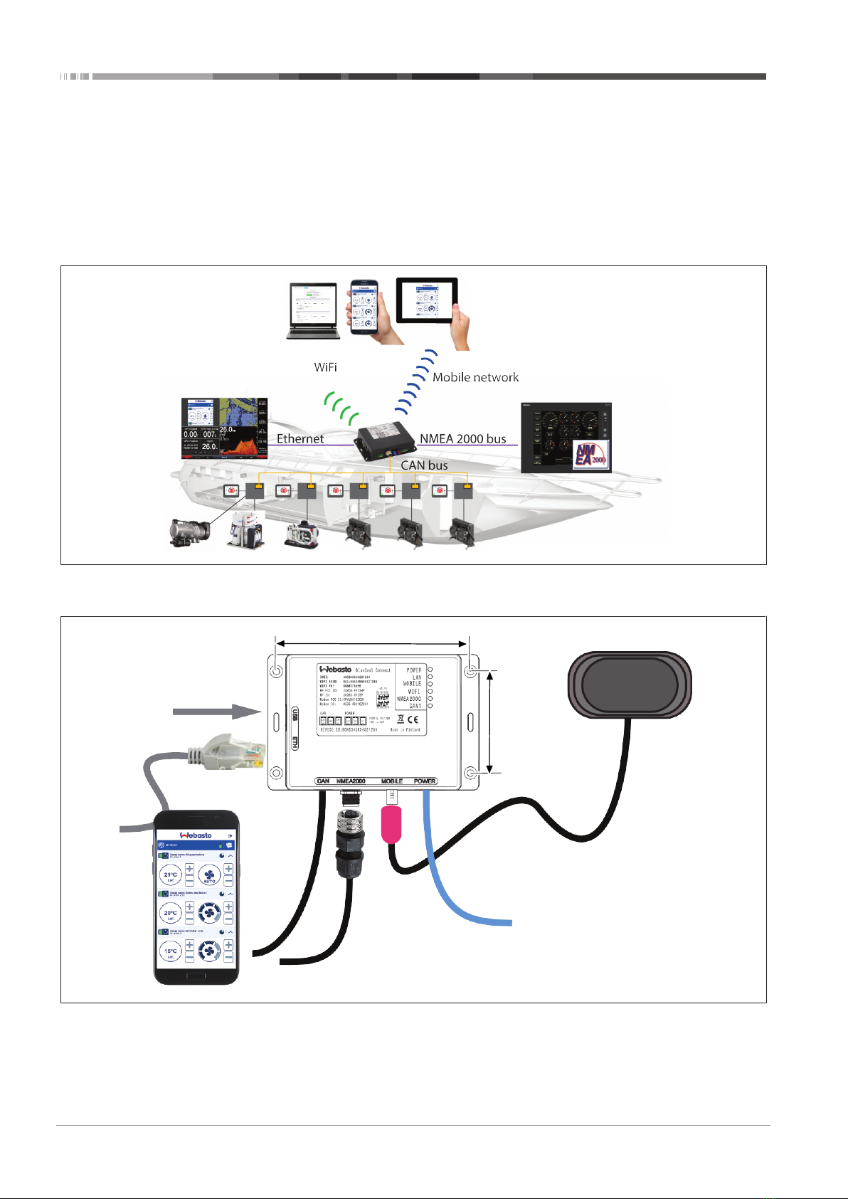
1. Find a suitable location for BlueCool Connect (BCC) inter-
face box (1), taking a suitable location for the antenna (2)
into consideration. You have a 3 m long cable to connect
the antenna to the BCC interface box.
2. Drill the holes for mounting the BCC interface box.
3. Position the BCC interface box so that any condense water
inside can exit the box; for instance by pointing the con-
nectors towards the floor.
4. Mount the BCC interface box, using suitable screws, or
bolts and nuts.
5. Connect the power cable (3), securing the cables in such a
way that their connectors cannot be pulled out under any
circumstances. You must do this to fulfill ABYC (American
Boat and Yacht Council) requirements.
6. For more connection details, see the label on the box for
connections.
7. Connect the CAN bus (5). See the label on the box for the
connections.
8. Connect the NMEA (National Marine Electronics Associ-
ation) 2000 bus (4). Note that the NMEA 2000 bus is not
available in the first release.
9. Connect the LAN (Local Area Network) Ethernet cable (6).
10. Find a suitable location for the antenna (2), making sure
not to position the antenna on a metal surface, and then
mount the antenna securely.
11. Connect the antenna to the BCC interface unit using the 3
m long antenna cable.
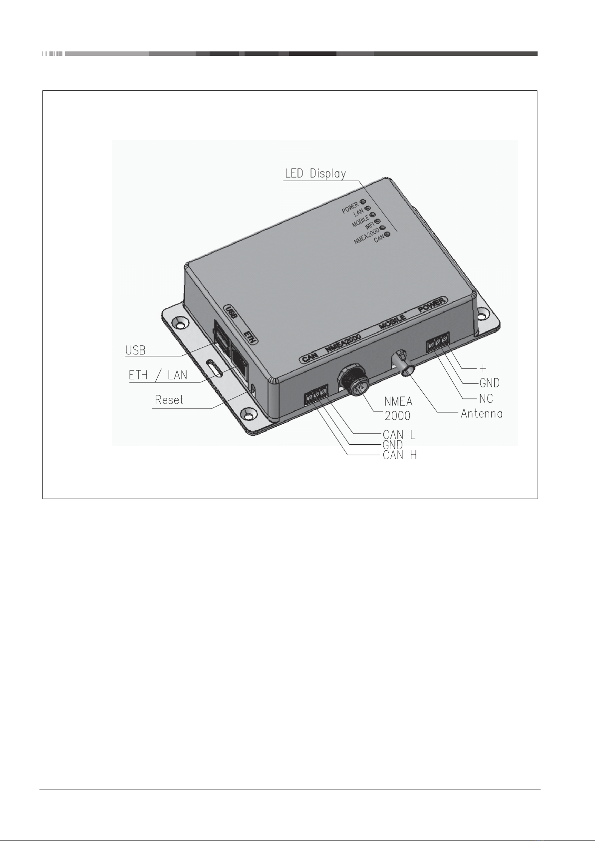
NOTE
You must connect the antenna even if you do not use
mobile connectivity; it may damage the antenna ampli-
fier if you use it without the antenna being connected.
The USB ports (7) on the BCC interface box are currently
without function but live at 5 V.
There is a reset button on the BCC interface box to restart it.
6.2 Software installation
An app enables you to control your BlueCool Connect from your
iOS or your Android device.
Example of the app on a mobile device
To install the app:
1. Verify if your mobile device (smartphone, tablet, and so on)
is connected to a network (an internet connection must be
available). Alternatively scan the appropriate QR code be-
low.
2. To access the relevant app store:
Browse to the Apple App store https://blue-
cool.webastoconnect.com/apps/ios and search for "Blue-
Cool Connect”.
- or -
Browse to the Google Play store https://blue-
cool.webastoconnect.com/apps/android and search for
"BlueCool Connect". Alternatively scan the appropriate QR
code below.
Fig.3 Use the Apple QR code above on the left, or the Android QR code
above on the right.
To create a Webasto account:
1. Follow the on-screen instructions to create a Webasto ac-
count.
2. Log in after the account has been created.
3. Enter the relevant Device-ID to add a BlueCool Connect
device to the app.
7 App navigation
7.1 Start menu BlueCool Connect
1
2
3
4
5
6
7
8
9
10
Fig.4
Screen contents
1. Logout
2. Settings
See chapter7.2, "Settings menu BlueCool Connect" on
page 6

7 | App navigation
6 / 12 2510264A OI-II BlueCool Connect_draft12
3. Show / hide groups
(this option is only shown when one or more groups have
been created) see chapter7.5, "Creating new groups" on
page 7
4. Expand / Collapse unit controls
5. Unit settings
See chapter7.4, "Settings menu BlueCool AC unit" on page
7
6. Timer
See chapter7.7, "Setting the Timer" on page 8
7. Add a new BlueCool Connect
See chapter7.8, "Adding a new BlueCool Connect" on
page 8
8. On / Off switch for units / groups
9. Antenna icon and your BlueCool network name
See chapter7.2, "Settings menu BlueCool Connect" on
page 6
If the mobile connection is available, then the antenna
icon (9) is shown.
If the device is only connected via Ethernet, then the Ether-
net connector icon (10) is shown.
If both the mobile and the Ethernet connection fail, no icon
is shown.
The BCC is a remote-controlled application. To avoid the BCC
being switched on accidentally, select the logout icon (1) to log
out. Always log out in your absence.
7.2 Settings menu BlueCool Connect
WMS000073A
Fig.5
This menu enables you to access the settings options of the
BlueCool Connect device. You can only access all options if your
BlueCool Connect device is connected to a mobile network or
another source of internet access. For connection options, see
the “Global Devices” option in the start screen of the app.
Function Description
Subscription Check the expiration date (X)
Buy or renew a subscription (X)
Function Description
Info Check the current version of BlueCool
Connect firmware (X)
Settings Change the name of the BlueCool Con-
nect device
Group manage-
ment
Create a group of A/C units to operate
these simultaneously
Device owners View or delete device owners (X), see
chapter7.8, "Adding a new BlueCool Con-
nect" on page 8
Language Select the screen language
Administration Access the Web Expert Tool through an in-
ternet browser (X)
Options that are not shown in the menu when connected loc-
ally via ad-hoc WiFi are marked (X).
7.3 Operating a unit
1
2
3
4
5
6
7
8
9
Screen contents:
1. Toggle for units / groups
2. Expand / Collapse the Unit control panel
3. Unit timer
4. Blower control buttons / Auto setting
5. Blower settings display
6. Temperature control buttons
7. Temperature setting display
8. Actual cabin temperature
9. On / Off switch for units / groups
The start menu shows all units in your BCC network. You can
control units individually and by group.
nSelect individual on / off sliders (9) to switch on / off a
single unit or group.
nSelect the drop-down arrows (2) to open the temperature
and blower control panel.
nThe unit name and current temperature are shown on the
top left, next to the on/off slide.
nClick the clock icon (2) to automatically switch the unit on /
off by timer. See chapter7.7, "Setting the Timer" on page
8

App navigation | 7
2510264A OI-II BlueCool Connect_draft12 7 / 12
nClick the [+] and [-] icons (6) to set the cabin temperature.
nClick the [+] and [-] icons (4) to adjust the blower settings.
7.4 Settings menu BlueCool AC unit
WMS000075A
Fig.6
The settings menu controls the settings of each A/C unit
Function Description
Info – View the connected A/C unit type
– View the CAN-Bus address of the connec-
ted A/C unit. The CAN-Bus address can be
changed via the BlueCool MyTouch dis-
play or a USB connection to the A/C unit
with the BlueCool Expert Tool. (after the
CAN-Bus address has been changed, re-
start to remove non-used devices from
the start screen)
– View firmware of the connected A/C unit
– View cold water temperature on chiller or
air handlers (optional)
Settings – Change the A/C unit name
– Change operation mode of the unit
– Change temperature unit from display in
°C to °F
Dehumidific-
ation
– Select the number of dehumidification
cycles per 24 h
– Select duration of heating time
– Select duration of cooling time
– See the installation instructions of the A/C
unit for more information.
Error Code Check the latest error code. Error codes are dis-
played if the system is not working properly
7.5 Creating new groups
Creating a group of units enables you to operate and control
the units simultaneously.
nTo create a group, select “Create groups” from the Settings
menu.
nTo remove a group, select the group that you want to re-
move from the Settings menu. See chapter7.2, "Settings
menu BlueCool Connect" on page 6.
1
2
3
Fig.7
Screen contents:
1. The Save button saves the created group with its units.
2. The Group name field enables you to provide an appro-
priate group name.
3. The A/C units fields enable you to add units to the group.
Fig.8
1. Tap the [+] icon on the right of the unit name to add the
unit to the group.
2. When you add a unit to a group, the [+] icon changes from
[+] to [-].
3. Tap the [-] icon on the right of the unit name to remove
any unit added in error from the group.
4. When you have finished, name the group and save it.
After you create the first group, the BCC adds a toggle switch
for groups on the start screen. See chapter7.2, "Settings menu
BlueCool Connect" on page 6 and chapter7.3, "Operating a
unit" on page 6.
Switch from unit view to group view to manage a group. In this
mode you can Start / Stop all grouped units, activate the timer,
and set temperatures and blower speeds.
The BCC does not display actual cabin temperatures because
you cannot view unit settings in group view, to display cabin
temperatures and other unit settings, you must first select unit
view.

7 | App navigation
8 / 12 2510264A OI-II BlueCool Connect_draft12
7.6 Operating a group
WMS000072A
1
2
Fig.9
Screen contents:
1. Toggle for showing / hiding groups in “On”
2. Group information
The operating display for groups looks similar to that for units.
Beside the group name, group information shows which units
are part of the group.
7.7 Setting the Timer
WMS000095A
1
2
3
Fig.10
You can set a timer to switch a group or unit on or off at a
given time.
1. Tap the timer symbol to open the timer menu.
2. Use the on / off slide in off position (1) to switch the timer
on.
3. Use the on / off slide in on position (2) to switch the timer
off.
4. Swipe up / down over a digit (3) to adjust the timer. The
timer counts in hours, minutes and seconds from the time it
is switched on.
Example:
To set the “Master bedroom” unit to come on at 5:45 PM
(17:45) when it is 3:00 PM (15:00), set the timer to 2 H(ours),
45 M(inutes) and 00 S(econds).
7.8 Adding a new BlueCool Connect
Fig.11
The BlueCool Connect (BCC) app enables you to operate BCC
devices installed on different boats.
To add another BCC interface to the app, tap the option “Add
new BlueCool Connect” in the initial start menu.
WMS00129A
Fig.12
In the next screen, first enter the ID of the BlueCool Connect
device that has to be added. Next, tap “Add device” and follow
the on-screen instructions.

Error codes | 8
2510264A OI-II BlueCool Connect_draft12 9 / 12
8 Error codes
Code Probable cause Probable solution
A10 Device is not responding
The error codes depend on the A/C units used. Please refer to
the installation manual for the installed A/C unit’s error codes,
explanation and solution.
9 Technical data
Parameter BlueCool Connect
Operating voltage range [V] 9 – 33
Power consumption [W] 13.5
Input CAN
Output Wi-Fi
Mobile (Telephone) Network
LAN - Ethernet
NMEA2000
Dimensions [mm] 140 x 104.9 x 33.8 (L x B x H)
Weight [kg] 0.34
Operating temperature [°C] -40 - +80
10 CE-declaration of
conformity
The BlueCool Connect was developed, manufactured, tested
and supplied in accordance with the relevant directives, regula-
tions and standards for safety, EMC and environmental compat-
ibility.
Webasto declares that the product BlueCool Connect was man-
ufactured and delivered in accordance with the directives and
regulations.
You can find the complete CE Declaration of Conformity in the
download area at https://dealers.webasto.com.

11 | Annex
10 / 12 2510264A OI-II BlueCool Connect_draft12
11 Annex
Fig.13

Annex | 11
2510264A OI-II BlueCool Connect_draft12 11 / 12
Fig.14

Ident No. 2510264A • 07/2020 • Errors and omissions excepted • © Webasto Thermo & Comfort SE
These are the original instructions. The English language is binding.
You can request your language if it is missing. The telephone number of each country can be found in the Webasto ser-
vice centre leaflet or the website of the respective Webasto representative of your country.
www.webasto.com
2510264A
Webasto Thermo & Comfort SE
Postfach 1410
82199 Gilching
Germany
Company address:
Friedrichshafener Str. 9
82205 Gilching
Germany
Other manuals for BlueCool Connect
1
Table of contents
Other Webasto Recording Equipment manuals