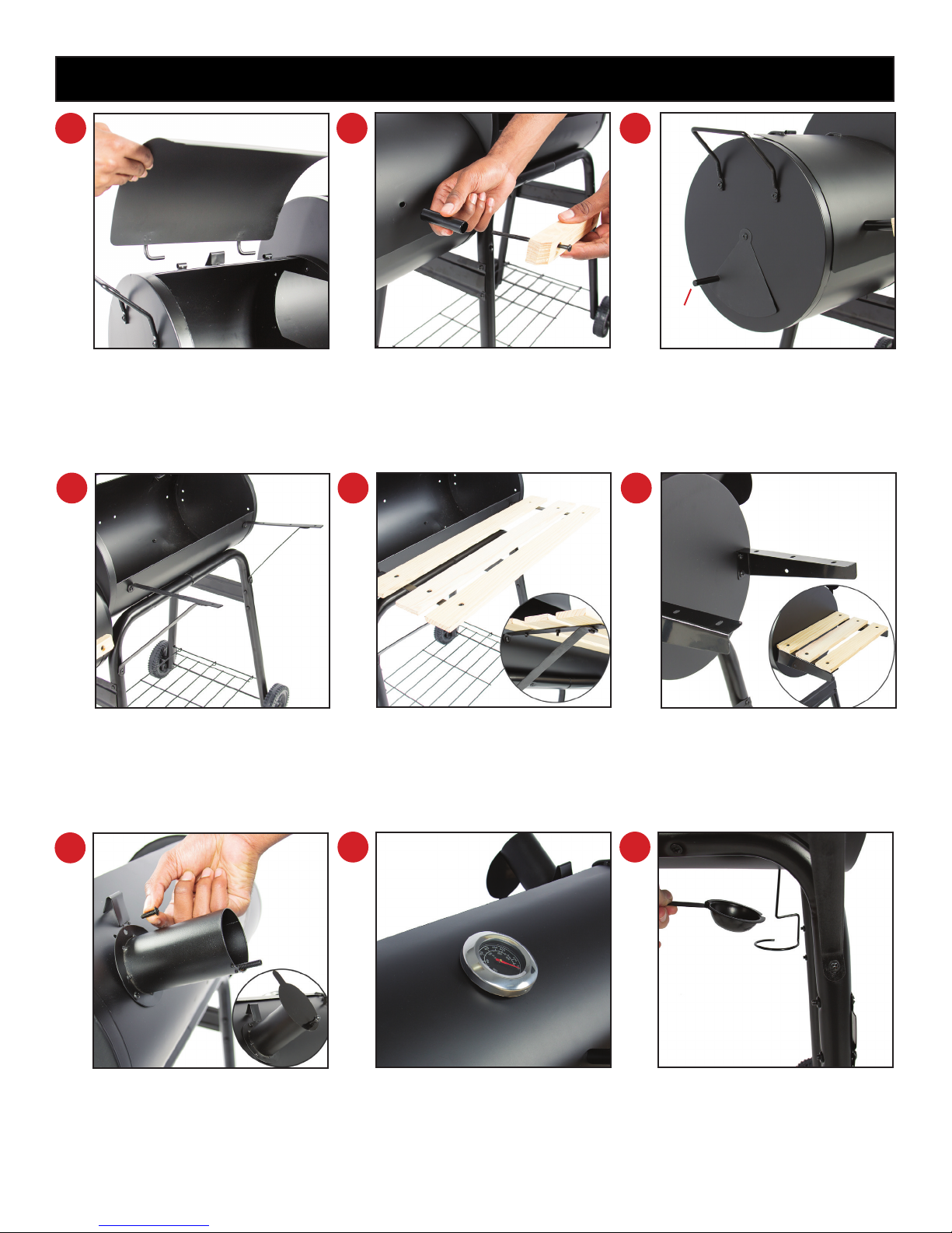
Next, slide the lids, part (M) and
part (N), into the holders and
secure using 4 (bolt E’s).
Attach part (T) to the front as-
sembly using 2 (bolt A’s) and then
attach part (S) to part (K) with 2
(bolt B’s) as shown.
Locate the circular hole on the
top of part (K) and attach part (X)
using 3 (bolt C’s). Slide part (Y)
over part (X) with the (spring) and
secure using the (steam cap).
Unscrew the nut located on ther-
mostat, part (CC), slide it in the
designated hole on part (M) and
secure.
Lastly, feed the grease catcher,
part (BB), through the hole on the
inside of part (K), and place part
(AA) on top.
Attach the handles to the lid
by sliding (bolt D) through the
handle, part (O), and then slide
part (P) over (bolt D) as shown.
Lay 3 wood beams (part U)
across part (S) and connect using
(bolt C).
Attach part (Q) and part (R) to
part (L) using 3 (bolt B’s). Attach
part (Z) using a nut from (bolt B).
Note: there is an extra nut added for this
part.
Attach part (W) to part (K) with
4 (bolt B’s). Lay 3 small wood
beams (part V) across and secure
using (bolt C).
10
16 17 18
11 12
13 14 15
Part Z