BDS RD-3151 User manual

Service Manual
RD-3151
Rear Delivery Dr. Assistant with
Swivel Bar
Rev 3 - 6-17-19 900-105

800.237.2303 ◆503.538.8756 ◆503.538.2845 Fax ◆www.beaverstatedental.com 1
RD-3151
Installation Under Cabinet Mount
1. Place the shipping carton in the desired location. Remove the unit from the shipping
carton.
2. Remove the full sized mounting template from the service manual. Place in desired
location and mark four places to be drilled. We recommend the faceplate to be offset
inward 1/8" from the front of the counters edge.
3. Pre-drill a hole 1/2" deep using a 5/32" drill bit. Do not drill through the counter top
4. Slidetheunitapartbyseperatingthefaceplateassemblyfromthexedbodyas-
sembly.Withtheunitfullyextended,lineuptheouterchassisaligningtheholeswith
thepre-drilledholes.Placea1/4"HexScrewinonecornertolightlyfastenitusinga
3/8"HexDrive.Repeattheprocessuntilallfourscrewsareinstalled.Tightensecurly
making sure the face plate slides in and out freely.
5. Inserttheumbilicaltubinginrstandfollowwiththeunit.
6. Mount the holder bar with holders in desired location under counter top.
7. Installoptionalmastervalveassemblies,withlterandregulator,ontothemanual
shut-offvalves.(Pressuresarepresetatthefactory:80psiair,40psiwater).
8. Connect the supply tubings to the appropriate air and water supply lines.
Checkairpressure,adjustto80psiifnecessary.
Checkwaterpressure,adjustto40psiifnecessary.
Testhandpiecesforproperfunction.
Testsyringeforproperpressureandfunction.
Final
Adjustments
NOTE
This unit requires a regulated air and water supply.
Filters are highly recommended.

800.237.2303 ◆503.538.8756 ◆503.538.2845 Fax ◆www.beaverstatedental.com
2
RD-3151
Operation 1. Turnonthemasterswitchlocatedontherightsideofthefaceplate.
2. Thehandpieceisautomaticallyactivatedwhenliftedfromtheholder.
3. Depress the foot control to activate each handpiece. Pressure is shown on the gauge for
the handpiece being used.
4. Individual handpiece pressure adjustments are located on the autoblock inside the
unit.Toadjustthepressuretoeachhandpiece:
a. Turnadjustmentscrewclockwise to decrease the handpiece pressure.
b. Turnadjustmentscrewcounter-clockwise to increase the handpiece pressure.
5. Handpiece coolant water can be turned on or off with the toggle switch located in the
lower center of the faceplate.
6. Watercoolantowadjustmentislocatedtotherightofthewatercoolanttoggleswitch.
Thepurgeswitchushesfreshwaterthroughthewatercoolantsystem.Guidelinesfromthe
CenterforDiseaseControl(CDC)recommendsthateachhandpiecebeushed(purged)20to
30 seconds between patients and several minutes at the beginning of each day. Handpieces
must be removed from the holder to activate the purge system.
CAUTION
Whenadjustingthehandpiecepressure,donotover-
tighten the screws. Damage may result.
Control Panel RD-3151
Handpiece Purge
Handpiece Water
Flow Control Knobs
Purge
ToggleSwitch
Master Switch
Air Coolant
Water On/Off
Indicator

800.237.2303 ◆503.538.8756 ◆503.538.2845 Fax ◆www.beaverstatedental.com 3
Troubleshooting
Symptom
Possible Causes
Symptom
Possible Causes
Symptom
Possible Causes
Handpiece lacks power.
A. Impropersupplypressurefromcompressor(80psi).
B. Checkhandpiecepressureadjustmentonunit.
C. Airltermaybeplugged.
D. Pinched supply tubing.
E. Defectivehandpiecegasketatconnectionwithtubing.
F. Defective handpiece.
Water coolant does not shut off when foot control is released.
A. Adjustairpressureto80psi—waterpressureto40psi.
B. Footcontrolisnotexhausting.
C. Defective water relay valve.
More than one handpiece is operating.
A. Handpiece is not all the way in the holder.
B. Improperadjustmentonpilotvalveinthehandpieceholder.
C. Defective shuttle valve to gauge.
Insufcientwatercoolant.
A. Adjustcoolantowvalve.
B. Waterltermaybeplugged.
C. Handpiece may be plugged.
D. Pinched supply tubing.
E. Improperadjustmentofwaterrelayvalve
Water coolant is running from handpiece while in the holder.
A. Water pressure too high.
B. Air pressure too low.
C. Handpieceholderoutofadjustment.
Water coolant is running continuously.
A. Purgeswitchison(onapplicablesystems).
B. Water pressure to high.
C. Handpieceholderoutofadjustment.
D. Defective water relay valve.
Symptom
Possible Causes
Symptom
Possible Causes
Symptom
Possible Causes

44
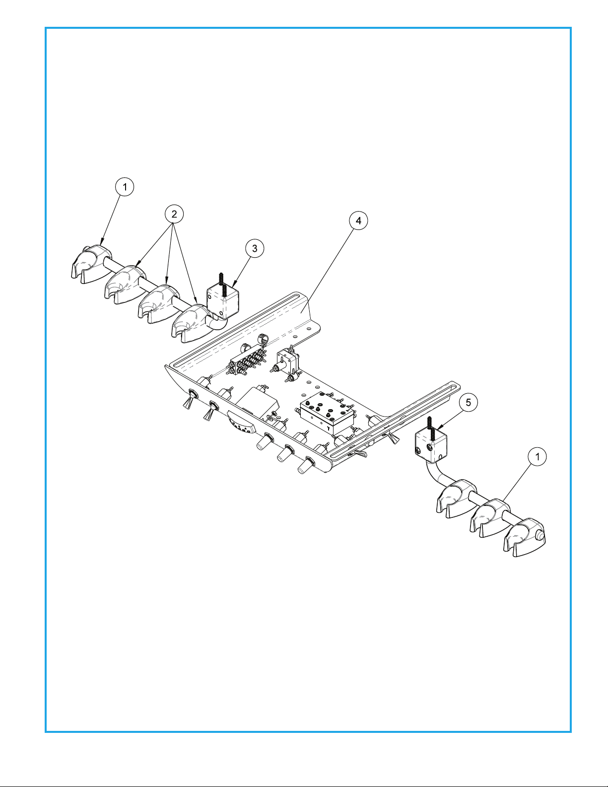
REAR DELIVERY DR. ASSISTANT SWIVEL BAR
RD-3151
ITEM
1
2
3
4
5
PART DESCRIPTION
Syringe Holder. .......................................
Auto Holder.............................................
Pivoting Holder Bar 10 -1/2”..............
Rear Deliver Unit Head........................
Cabinet/Wall Holder Bar 8“................
PART NUMBER
141-100
122-100
105-177
3100-RD
105-170
QTY
4
3
1
1
1

55 REAR DELIVERY UNIT HEAD ASSEMBLY
3100-RD
ITEM
1
2
3
4
5
6
7
8
9
10
11
12
13
14
15
16
17
PART DESCRIPTION
4-40 Hex Nut ...........................................
Washer, No. 6 ...........................................
1/2”Plug....................................................
Shuttle Valve............................................
Manifold....................................................
Rectangular Gauge...............................
Pneumatic Indicator.............................
Chassi.........................................................
3 Way Momentary Toggle Valve.......
3 Way Toggle Valve ...............................
3 Way Toggle Valve................................
Needle Flow Valve. ................................
Water Relay Valve ..................................
Autoblock.................................................
Screw, 18-8 ...............................................
Washer, 0625 OD x .199.......................
Spacer, A-Series ......................................
PART NUMBER
002-017
003-032
010-013
014-012
023-003
026-003
026-020
103-330
120-005
120-007
120-000
121-000
123-000
125-030
001-270
003-070
103-334
QTY
2
2
3
1
1
1
1
1
1
1
2
3
1
1
4
4
4

66
Water Relay Valve 123-000
ITEM
1
2
3
4
5
6
7
8
9
PART DESCRIPTION
Molded Body....................................
Molded Clip.......................................
Pin, 1/16" x 5/16".............................
Handpiece Actuator Lever...........
Screw, 4 x 1/2" ..................................
Screw, 8 x 1/2" ..................................
Washer Tray Mount Spacer.........
Automatic Holder Valve................
Set Screw, 6-32 x 3/16"..................
PART NUMBER
122-101
122-102
009-010
122-103
001-019
001-018
003-004
122-031
005-019
QTY
1
1
1
1
2
2
1
1
1
AUTOMATIC HANDPIECE HOLDER
122-100

77 NON-RETRACTION WATER RELAY VALVE
123-000
ITEM
1
2
3
4
5
6
7
8
9
10
11
12
13
14
PART DESCRIPTION
Cartridge Body Assembly.............
Set Screw, 4-40 x 5/8".....................
Body....................................................
Piston..................................................
Diaphragm........................................
Cap.......................................................
Screw, #6 x 1/2"................................
Barb, 10-32 x 1/16".........................
Plastic Washer, 1/4"........................
Valve Body..........................................
Spring.................................................
O-Ring, 002.......................................
O-Ring, 001......................................
Stem...................................................
PART NUMBER
123-018
005-028
123-013
123-014
127-031
123-012
001-267
022-009
003-001
123-017
008-011
017-502
017-501
123-015
QTY
1
1
1
1
1
1
4
1
1
1
1
1
2
1
Water Relay Valve 123-000
Air In
Water In
Water Out

88
AUTOMATIC HANDPIECE CONTROL BLOCK
125-030
ITEM
1
2
3
4
5
6
7
8
9
10
11
PART DESCRIPTION
Adjusting Stem................................
O-Ring, 021........................................
Screw, 6-32 x 1/4"...........................
Cap.......................................................
Plastic Washer, 8-32 x 1/16"........
Barb, 8-32 x 1/16"...........................
Diaphragm........................................
Body....................................................
Barb, 10-32 x 1/16"............................
Barb, 10-32 x 1/8"...........................
Plastic Washer, 1/4"........................
PART NUMBER
125-023
017-021
001-131
125-032
003-030
022-040
125-016
125-031
022-009
022-010
003-001
QTY
3
3
7
1
3
3
1
1
9
4
13
Drive Air In
OuttoGauge
Coolant Air In
Coolant Water In
Coolant Water Out
Drive Air Out
Coolant Air Out
Signal Air In
Handpiece Pressure
Adjustment
Theautomaticcontrolblockisthecontrolcenterforyourdentalunit.
Individualhandpiecepressureadjustmentsarelocatedonthe
autoblock.Toadjustthepressuretoeachhandpiece:
a. Turnadjustmentscrewclockwisetodecreasethe
handpiece pressure.
b. Turnadjustmentscrewcounter-clockwisetoincrease
the handpiece pressure.
CAUTION
When adjusting the handpiece
pressure,donotover-tightenthe
screws. Damage may result.

99
Drive Air In
OuttoGauge
Coolant Air In
Coolant Water In
MASTER VALVE
127-010-AIR
Batch Stamp
Located Here
Vent Hole
ITEM
1
2
3
4
5
6
7
8
9
10
11
12
PART DESCRIPTION
Set Screw, 1/4-20 x 5/8”.........................
Jam Nut, 1/4-20.......................................
Washer........................................................
Screw, 6-32 x 3/8”....................................
Cap...............................................................
Spring Seat...............................................
Spring.........................................................
Cup Seat.....................................................
Cup Seal......................................................
Seat..............................................................
O-Ring, 008................................................
Stem.............................................................
PART NUMBER
005-024
002-006
003-015
001-041
127-033
127-043
008-008
127-044
017-200
127-026
017-008
127-024
ITEM
13
14
15
16
17
18
19
20
21
22
23
ITEM
24
25
26
27
28
29
30
31
32
33
34
PART DESCRIPTION
O-Ring, 004........................................
Spring..................................................
O-Ring.................................................
Body.....................................................
Plastic Washer, 1/4”........................
Barb, 10-32 x 1/8”............................
O-Ring, 001........................................
Stem....................................................
O-Ring, 003........................................
Spring..................................................
O-Ring, 007.................................. .....
PART DESCRIPTION
Plug...................................................................
Barb, 10-32 x 1/16”......................................
Cap Inlet..........................................................
Filter Element, 100 Micron........................
O-Ring, 018.....................................................
Filter Element, 35 Micron..........................
Gauge...............................................................
Piston................................................................
Gasket..............................................................
Cap....................................................................
Plug...................................................................
PART NUMBER
017-504
008-028
017-018
127-040
003-001
022-010
017-501
127-045
017-103
008-040
017-007
PART NUMBER
020-026
022-009
127-041
119-005
017-022
119-004
026-001
123-014
127-031
123-030
001-001
QTY
1
1
1
8
1
1
2
1
4
3
2
1
QTY
1
1
1
1
5
2
2
1
1
1
1
QTY
1
1
1
1
2
1
1
1
1
1
2
Constant Air Out
Out to Foot Control
ToMaster
On/Off Switch
Regulator Pressure
Adjustment
PressureGauge
Air—80lbspsi
Water—40lbspsi
Remove Brass Knurled Cap
toReplaceFilterElement

1010
MASTER VALVE
127-010 WATER
Vent Hole
Batch Stamp
Located Here
ITEM
1
2
3
4
5
6
7
8
9
10
11
PART DESCRIPTION
Set Screw, 1/4”-20 x 5/8”.......................
Jam Nut, 1/4”-20......................................
Washer........................................................
Screw, 6-32 x 3/8”....................................
Cap...............................................................
Spring Seat...............................................
Spring.........................................................
Cup Seat.....................................................
Cup Seal......................................................
Seat..............................................................
O-Ring, 008................................................
PART NUMBER
005-050
002-006
003-015
001-041
127-023
127-043
008-008
127-044
017-200
127-026
017-008
ITEM
12
13
14
15
16
17
18
19
20
21
22
ITEM
23
24
25
26
27
28
29
30
31
32
33
PART DESCRIPTION
Stem....................................................
O-Ring, 004........................................
Spring..................................................
O-Ring.................................................
Body.....................................................
Plastic Washer, 1/4”........................
Barb, 10-32 x 1/8”............................
Plug......................................................
O-Ring, 001........................................
Stem....................................................
O-Ring, 003........................................
PART DESCRIPTION
Spring........................................................
O-Ring, 007......................................... .....
Plug............................................................
Cap Inlet.....................................................
Filter Element, 100 Micron..................
O-Ring, 018...............................................
Filter Element, 35 Micron.....................
Gauge.........................................................
Piston..........................................................
Gasket.........................................................
Cap...............................................................
PART NUMBER
127-024
017-504
008-028
017-018
127-040
003-001
022-010
001-001
017-501
127-045
017-103
PART NUMBER
008-040
017-007
020-026
127-041
119-005
017-022
119-004
126-001
123-014
127-031
123-012
QTY
1
1
1
8
1
1
1
1
1
1
1
QTY
1
1
1
1
1
1
1
4
2
1
1
QTY
1
1
1
1
1
2
1
1
1
1
1
Water Out
Regulator Pressure
Adjustment
PressureGauge
Air—80lbspsi
Water—40lbspsi
Remove Brass Knurled Cap
toReplaceFilterElement

1111 3-WAY IC SYRINGE
113-400
ITEM
1
2
3
4
5
6
7
8
9
10
11
12
PART DESCRIPTION
Syringe Tip ..................................
Syringe Tip Nut ............................
O-Ring, 006 .................................
O-Ring, 228-040..........................
Syringe Tip Adapter.....................
O-Ring, 003 .................................
Syringe Head...............................
Syringe Button Repair Kit ............
Pin, Syringe Cartridge .................
Plastic Washer, 8-32....................
Barb, 8-32 x 1/16’’ .......................
Syringe Handle...........................
PART NUMBER
113-030
113-402
017-006
017-023
113-227
017-003
113-405
113-403
113-008
003-030
022-040
113-236
QTY
1
1
2
1
1
1
1
2
1
2
2
1
Quick-disconnect Syringe Tip Assembly 113-230
1. Remove the existing hex nut. A hex nut wrench has been
provided.
2. Remove the syringe tip adapter using the hex wrench.
3. Insert the new syringe tip adapter into the syringe head and
tighten using the hex wrench.
4. Place the two (2) O-Rings into the syringe tip nut.
5. Screw the syringe tip nut onto the syringe tip adapter and
tighten using the hex wrench.
6. Push the syringe tip into the syringe tip nut until it snaps into
place.
Replace Syringe Tip
1. Pull the dirty syringe tip out and insert a clean syringe tip into
the syringe tip nut until it snaps into place.

1212
FOOT CONTROL
126-000
ITEM
1
2
3
4
5
6
7
8
9
10
11
12
13
PART DESCRIPTION
Ring......................................................
Cover....................................................
Spring.................................................
O-Ring, 012.......................................
Stem....................................................
Body....................................................
Poppet................................................
Spring..................................................
O-Ring, 013........................................
Baseplate...........................................
Screw, 4-40 x 1/4"...........................
Rubber Pad.......................................
Screw, 6-32 x 1/4"...........................
Repair kit...........................................
PART NUMBER
126-260
126-200
008-005
017-012
126-005
126-004
126-006
008-006
017-013
126-003
001-005
126-007
001-004
126-025
QTY
1
1
1
1
1
1
1
1
1
1
4
1
2


Manifold
Block
023-001
1/4" Clear - Constant Air In
1/8" Brown - On/Off (flow out) to M.V. 1/4" Blue - Water In
1/8" Yellow - On/Off (flow In) from M.V.
Circled letters indicate connection at Junction Box
Junction Box
1/4" Gray
1/4" Clear
1/8" Blue
1/8" Clear
1/8" Gray
1/8" Brown
1/8" Yellow
1/4" Blue
1/4" Gray - In From Foot Control
Wet Dry Option
Chip Air Option
Syringe Handpiece 2 Handpiece 3
Handpiece 1
HP Pressure
Gauge
026-003
Non-Retracting
Water Relay
Valve
123-000
Air 80
Utility Center
Water 40
Mini
Regulator
128-018
On/Off
Toggle
120-000
Optional
Water Bottle
System
Air Regulator
127-010-A
Water
Regulator
127-010-W
HVE
Foot Control
126-000
Optional Foot Controls
126-133 (Chip Blower)
126-160 (Wet/Dry)
126-203 (Wet/Dry & Chip Blower)
Syringe
Adjustment
Block
113-026
Vacuum
Cannister
131-036
S/E Syringe
Shuttle Valve
014-012
Auto Block
125-030
1
2
3
4
5
6
7
8
Master On/Off Toggle
120-000
On/Off Indicator
026-020
Purge On/Off Toggle
120-000
Water On/Off Toggle
120-000
HP coolant Flow 2
121-000
Air Coolant
121-000
HP coolant Flow 1
121-000
HP coolant Flow 3
121-000
Tee
To Syringe To HP 1 To HP 2 To HP 3
HP 1
HP 2
HP 3
Unit Head
1/8" Clear - Foot control option 126-153
1
2
3
5
678
4
HP 1
HP 2
HP 3
3 Handpiece Automatic Rear Delivery with Vacuum
RD-3151
BEAVERSTATEDENTAL,INC.
115S.ELLIOTTRD.
NEWBERG,OR97132USA
800-237-2303 503-538-8756
503-538-2845 FAX
Revision Date: 10-10-17

UNDERCOUNTERMOUNTTEMPLATE
RD-3103,RD-3153,RD-3102,RD-3152,RD-3150,RD-3101andRD-3151
Rev 2 - 6-17-19 900-283
.810”
11.42”
2.5”
FRONT EDGE
OF COUNTER
4X DRILL FOR
# 10 WOOD SCREW

BeaverstateDentalwarrantiesitsproducttobefreeofdefectsinmaterialandworkmanshipforFIVEFULL
YEARSfromthedateofpurchaseonallunits.Auto-blocksandstandardfootcontrol(126-000)arecoveredby
aLIFETIMEwarrantywhenfactoryinstalledaspartofacompletedentalsystem.Warrantyislimitedtorepair
or replacement by Beaverstate Dental. Products returned to the factory and determined to be defective will be
repairedorreplacedfreeofcharge.Thewarrantydoesnotcoverlightbulbs.BeaverstateDentalreservesthe
right to void all warranties if any product is installed by other than an authorized technician. Beaverstate's war-
rantydoesnotcoverdamagetoanysurfacenish,includingbutnotlimitedto,discolorationorabrasionfrom
cleaners,disinfectantsorlightsources.Noclaimforlabororconsequentialdamageswillbeallowed.Return
items must include a copy of the invoice or packing slip as proof of purchase.
WARRANTY

Beaverstate Dental Inc.
115 S. Elliott Rd.
Newberg, OR 97132
800-237-2303
503-538-8756
503-538-2845 Fax
www.beaverstatedental.com
Table of contents
Other BDS Dental Equipment manuals
Popular Dental Equipment manuals by other brands

Sirona Dental
Sirona Dental CEREC 3 operating instructions

Morita
Morita Lubrina HIM-1 Operation instructions

NSK
NSK FXZBS M4 Operation manual

Dentsply Sirona
Dentsply Sirona Cavitron Jet Plus Quick Maintenance Guide

Durr Dental
Durr Dental VistaScan Perio Plus Installation and configuration instructions

DCI Edge
DCI Edge SERIES 5 Instructions for use