BDS S-6307 User manual

Service Manual
S-6307
3 HP Automatic Euro Top Post Mount
Doctor’s System with Flex Arm
Rev 5 - 1-10-20 900-021M

800.237.2303 ◆503.538.8756 ◆503.538.2845 Fax ◆www.beaverstatedental.com 1
S-6307
Installation 1. Install the chair adapter as per instructions provided with the chair adapter.
2. Place the shipping carton in the desired location. Remove the unit with arm system
and unit from the shipping carton.
3. Insert the unit post into the chair adapter hub. Level, then tighten the set screws to
secure the post in place.
4. Place the adapter in the unit post and insert the umbilical into the unit post, pulling
it out through the bottom. Slide the arm knuckle into the adapter.
5. Cut the safety tie strap and carefully release the arm system.
6. Rotatetheexarm1800in a counter-clockwise direction so that the umbilical tubings
do not become crimped or twisted.
7. Remove the rigid arm end cap and tighten the cap screw to set the stop limits for
theexarm.Replacetheendcap.
8. Installmastervalveassemblies,withlterandregulator,ontothemanualshut-off
valves.(Pressuresarepresetatthefactory:80psiair,40psiwater).
9. Feed the supply tubings from the umbilical through the 3/4" hole in the utility center
housing. Screw in the spiral tubing to act as a strain relief.
10.ConnectthesupplytubingsasshownintheUtilityCenterTemplate&Guide.
Checkairpressure,adjustto80psiifnecessary.
Checkwaterpressure,adjustto40psiifnecessary.
Testhandpiecesforproperfunction.
Testsyringeforproperpressureandfunction.
Adjustexarmtension,ifnecessary.
Final
Adjustments
WARNING
The arm system is spring loaded. Before removing
thesafetytiestrap,rmlygrasptheexarmandhold
Arm Stop Cap Screw
800.237.2303 ◆503.538.8756 ◆503.538.2845 Fax ◆www.beaverstatedental.com
2
S-6307
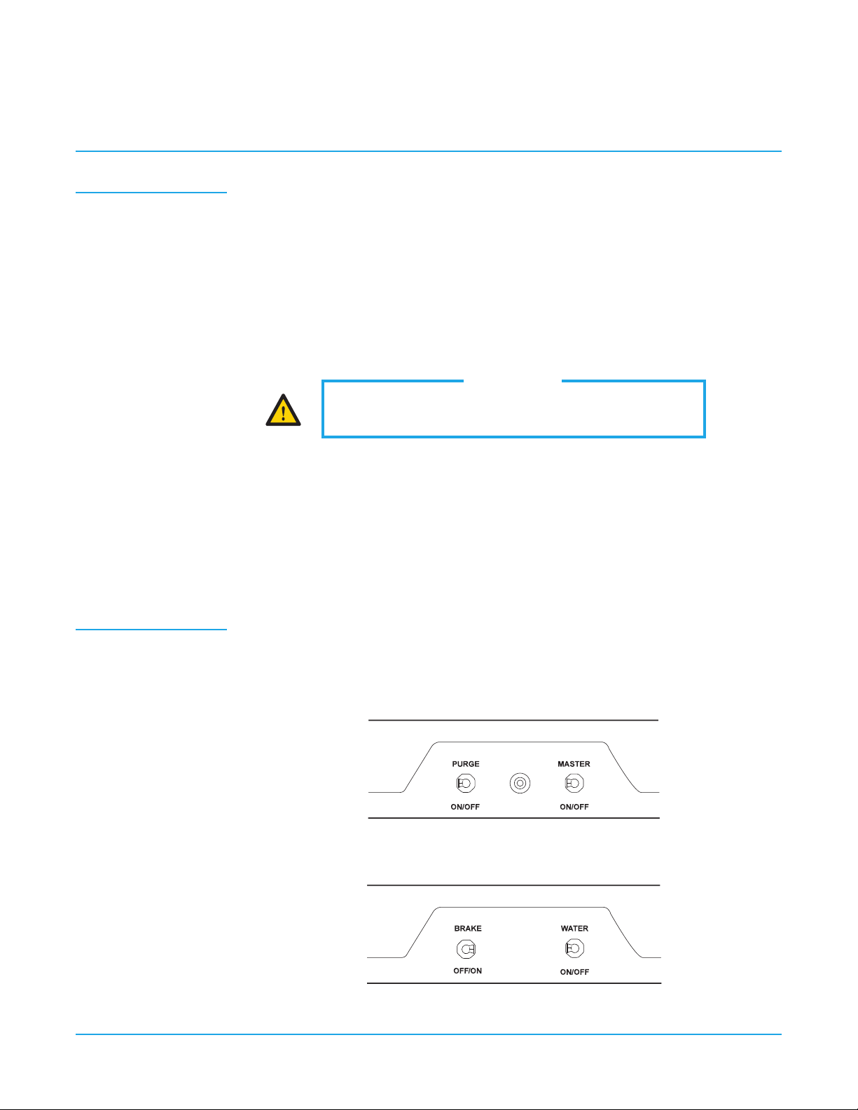
Operation 1. Turnonthemasterswitchlocatedontheleftsideofthecontrolhead.
2. Thehandpieceisautomaticallyactivatedwhenthewandispulledforward.
3. Depress the foot control to activate each handpiece. Pressure is shown on the gauge for
the handpiece being used.
4. Individual handpiece pressure adjustments are located on the autoblock inside the
controlhead.Toadjustthepressuretoeachhandpiece:
a. Turnadjustmentscrewclockwise to decrease the handpiece pressure.
b. Turnadjustmentscrewcounter-clockwise to increase the handpiece pressure.
5. Activatethewaterspraytothehandpiecebyippingthetoggleforthewaterlocatedon
the right side of the control head.
6. Watercoolantowadjustmentsarelocatedunderneaththecontrolhead.
7. Armbrakeswitchislocatedontherightsideofthecontrolhead.Thebrakeisonwhen
thetoggleispositionedtowardstherear(rightposition).Pulltheleverforward(leftposi-
tion)toreleasethearmbrake,adjustarmtodesiredlocationandmovelevertothe
rear(rightposition)toreapplythebrake.
Thepurgeswitch,locatedontheleftsideofthecontrolhead,ushesfreshwaterthroughthe
watercoolantsystem.GuidelinesfromtheCenterforDiseaseControl(CDC)recommendsthat
eachhandpiecebeushed(purged)20to30secondsbetweenpatientsandseveralminutes
at the beginning of each day. Handpieces must be removed from the holder to activate the
purge system.
CAUTION
When adjusting the handpiece pressure, do not over-
tighten the screws. Damage may result.
Handpiece Purge
Control Panel–Left Side
Control Panel–Right Side

800.237.2303 ◆503.538.8756 ◆503.538.2845 Fax ◆www.beaverstatedental.com 3
Troubleshooting
Symptom
Possible Causes
Symptom
Possible Causes
Symptom
Possible Causes
Handpiece lacks power.
A. Impropersupplypressurefromcompressor(80psi).
B. Checkhandpiecepressureadjustmentonunit.
C. Airltermaybeplugged.
D. Pinched supply tubing.
E. Defective handpiece gasket at connection with tubing.
F. Defective handpiece.
Water coolant does not shut off when foot control is released.
A. Adjustairpressureto80psi—waterpressureto40psi.
B. Footcontrolisnotexhausting.
C. Defective water relay valve.
More than one handpiece is operating.
A. Handpiece is not all the way in the holder.
B. Improperadjustmentonpilotvalveinthehandpieceholder.
C. Defective shuttle valve to gauge.
Insufcientwatercoolant.
A. Adjustcoolantowvalve.
B. Waterltermaybeplugged.
C. Handpiece may be plugged.
D. Pinched supply tubing.
E. Improper adjustment of water relay valve.
Water coolant is running from handpiece while in the holder.
A. Water pressure too high.
B. Airpressuretoolow.
C. Handpiece holder out of adjustment.
Water coolant is running continuously.
A. Purgeswitchison(onapplicablesystems).
B. Waterpressuretohigh.
C. Handpiece holder out of adjustment.
D. Defective water relay valve.
Symptom
Possible Causes
Symptom
Possible Causes
Symptom
Possible Causes
44
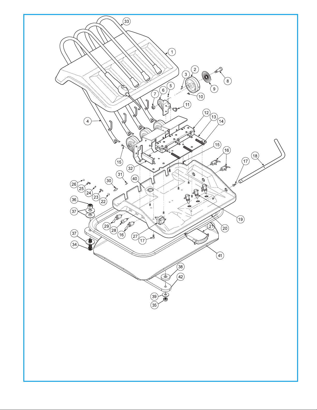
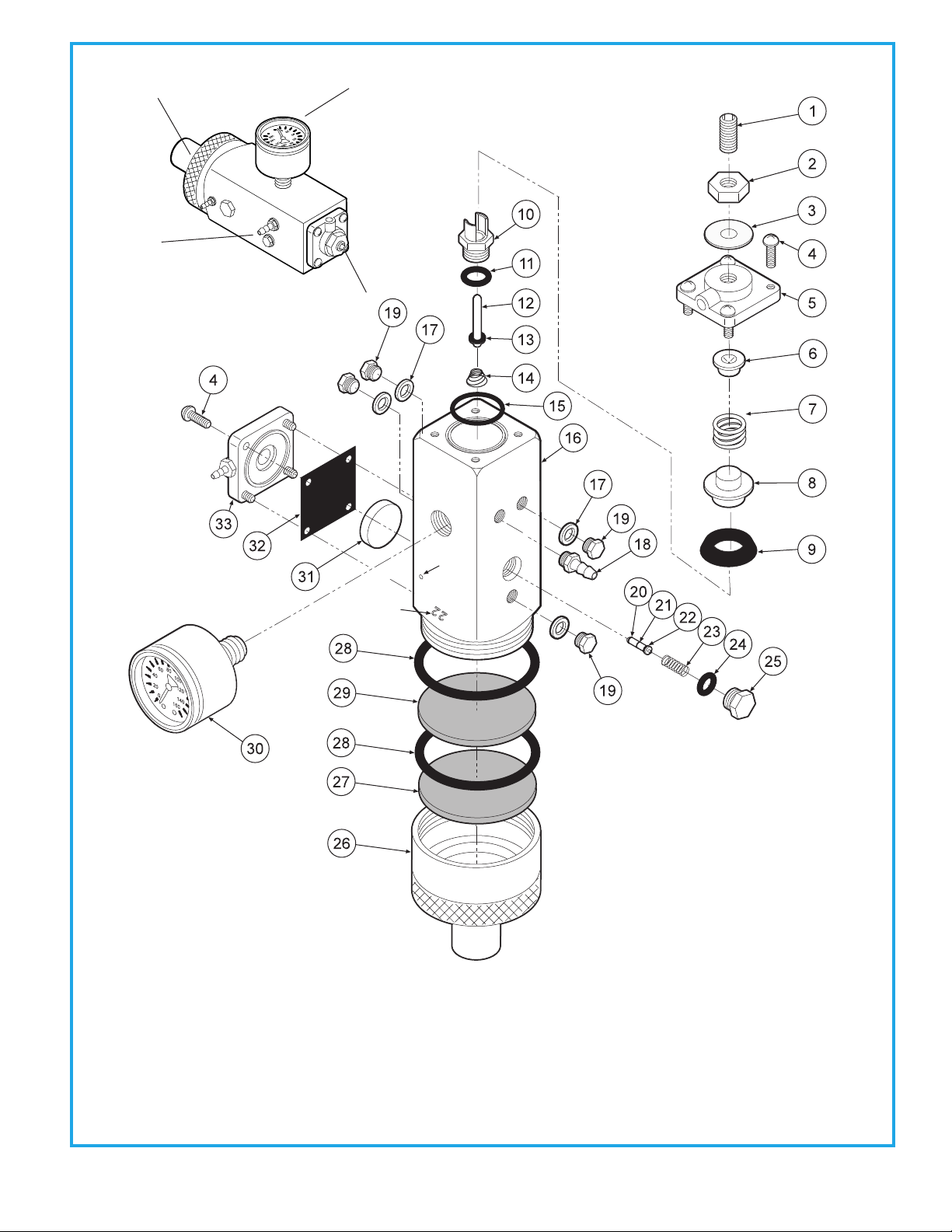
AUTOMATIC HANDPIECE CONTROL
S-6307
ITEM
1
2
3
4
5
6
7
8
9
10
11
12
13
14
PART DESCRIPTION
Cover................................................................
Euro Cam ........................................................
Pin, 1/8”x 1/2“ ...............................................
Euro Wand Assembly ................................
Set Screw, 4-40 x 3/16”...............................
Euro Cam Bracket........................................
Nylon Locknut, 10-32 .................................
Euro Pivot Shaft............................................
Euro Cam Spring..........................................
Set Screw, 6-32 x 3/8”.................................
Automatic Holder Valve ............................
Automatic Handpiece Block....................
Chasis...............................................................
Spring, Euro ...................................................
PART NUMBER
107-092
116-001
009-029
116-008
005-001
116-002
002-027
116-005
008-033
005-012
122-044
125-130
107-090
008-035
ITEM
15
16
17
18
19
20
21
22
23
24
25
26
27
28
ITEM
29
30
31
32
33
34
35
36
37
38
39
40
41
42
PART DESCRIPTION
Screw, 6-32 x 3/8”...........................
3-way Toggle Valve .......................
Screw, 10-32 x 3/8”........................
Holder Bar........................................
Needle Flow Valve.........................
Base ....................................................
Gauge ................................................
Ferrule, 1/4”......................................
Barb, 10-32 x 1/8”...........................
Plastic Washer, 1/4”........................
Barb, 10-32 x 1/16”.........................
Ferrule, 1/8”......................................
Water Relay......................................
Indicator............................................
PART DESCRIPTION
Momentary Valve ............................
Shuttle Valve......................................
Plastic Tee, 1/16”...............................
Handpiece Manifold.......................
Euro Wand Assembly .....................
Screw, 5/16-18 x 1-1/4”..................
Nut 1/4-20..........................................
Lock Nut, 5/16-18.............................
3/8 Nylon Washer............................
Tray Mount Spacer Washer ..........
Tray Mount Friction Washer..... ....
Tray, 9-3/4 x 13-1/4..........................
Tray Holder.........................................
Euro Tray Arm....................................
PART NUMBER
001-041
120-000
001-070
107-093
121-000
107-091
026-003
117-008
022-010
003-001
022-009
117-007
123-000
026-020
PART NUMBER
120-005
014-012
022-033
023-001
116-009
001-184
002-023
002-033
003-010
003-022
003-023
010-001
107-047
107-094
QTY
1
4
4
1
4
4
4
4
4
4
3
1
1
3
QTY
10
3
4
1
4
1
1
5
4
14
11
48
3
1
QTY
1
1
2
1
4
1
1
1
3
1
1
1
1
1
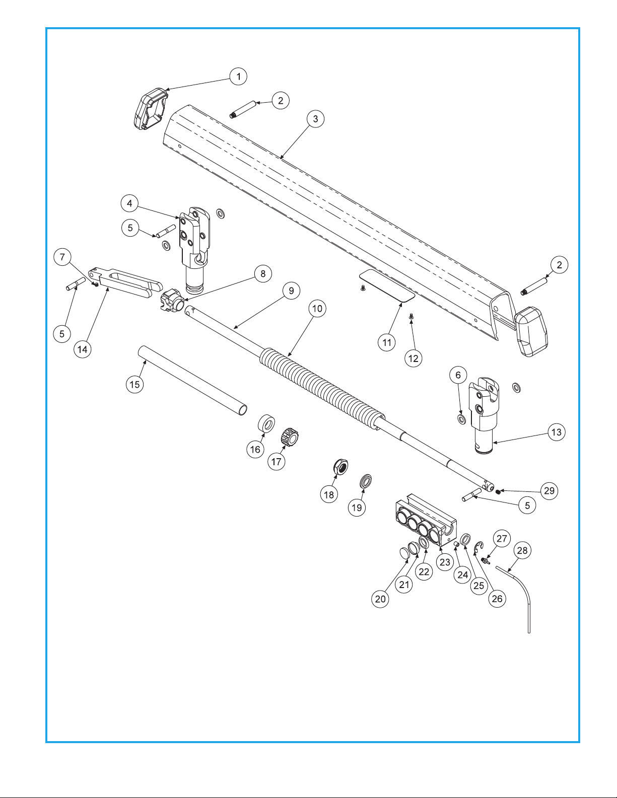
55 FLEX ARM WITH PNEUMATIC BRAKE
106-336
ITEM
1
2
3
4
5
6
7
8
9
10
PART DESCRIPTION
End Cap...................................................
Pin, Arm Housing.................................
Arm Housing.........................................
Arm Knuckle..........................................
Pin Rod....................................................
Plastic Washer.......................................
Set Screw, 10-32 x 3/16" ....................
Spring Slider..........................................
Rod............................................................
Spring ......................................................
PART NUMBER
106-319
009-030
106-314
106-322
009-031
003-040
005-037
106-311
106-327
008-019
ITEM
11
12
13
14
15
16
17
18
19
20
ITEM
21
22
23
24
25
26
27
28
29
PART DESCRIPTION
Plug Adjustment.......................................
Screw, 6-32 x 1/4"......................................
Head Knuckle.............................................
Arm Fork Link.............................................
Sleeve............................................................
Seat, Flex Arm Spring..............................
Adjustment Nut ........................................
Nut, Hex, Jam 9/16-18, Nylon Insert ...
Collar, w/Shoulder, Brake, Flex. .............
Brake Pad.....................................................
PART DESCRIPTION
Piston, Brake.............................................
U-Cup. .........................................................
Brake Housing..........................................
Ferrule, Delrin, 1/8".................................
Brake Collar, Threaded .........................
Ring,Truarc, 5133-43..............................
Barb 10-32 x 1/16"..................................
1/8" Supply Line, Black..........................
Socket Set Screw, 10-32 x 1/4"...........
PART NUMBER
106-329
001-133
106-337
106-318
106-321
106-320
106-325
002-011
106-338
106-313
PART NUMBER
106-317
017-204
106-316
117-007
106-324
006-004
022-059
115-028
005-035
QTY
2
2
1
1
3
4
1
1
1
1
QTY
1
2
1
1
1
1
1
1
1
8
QTY
8
8
1
1
1
1
1
11
1

66
FLEX ARM SYSTEM WITH PNEUMATIC BRAKE, TOP POST MOUNT
106-307
ITEM
1
2
3
4
5
6
7
8
9
PART DESCRIPTION
Flex Arm..................................................
Thrust Washer, Small...........................
End Cap...................................................
Set Screw, Half Dog.............................
Rigid Arm................................................
Pivot Mount...........................................
Snap Ring ...............................................
Plug Square, 3/4" ..................................
Bronz Bushing........................................
PART NUMBER
106-336
003-038
106-326
005-007
106-360
106-355
006-002
010-042
013-019
QTY
1
2
1
2
1
1
1
1
1

77 UTILITY CENTER
144-018
ITEM
1
2
3
4
PART DESCRIPTION
Utility Center Lid...........................
Manual Shut-off Valves...............
Master Shut-off Valve Kit............
Utility Center Housing................
Utility Center Kit............................
Plug ,10-32.............................
Screw, #6 x 3/4" ....................
Plastic Washer, 1/4".............
Plug, 3/4" ................................
Plug, 1-3/8" ............................
Plug, 1/2" ................................
Plug, 1-1/2" ............................
Plug, 2-1/4" ............................
Plug, 13/16”............................
Barb, 10-32 x 1/16"..............
Barb, 10-32 x 1/8" ................
Ferrule, 1/8" ...........................
PART NUMBER
144-005
020-022
127-012
144-004
010-055
001-001
001-063
003-001
010-005
010-008
010-013
010-015
010-017
010-016
022-009
022-010
117-007
QTY
1
2
1
1
1
1
6
2
2
1
1
1
1
2
1
1
4

88
UTILITY CENTER INSTALLATION
144-018
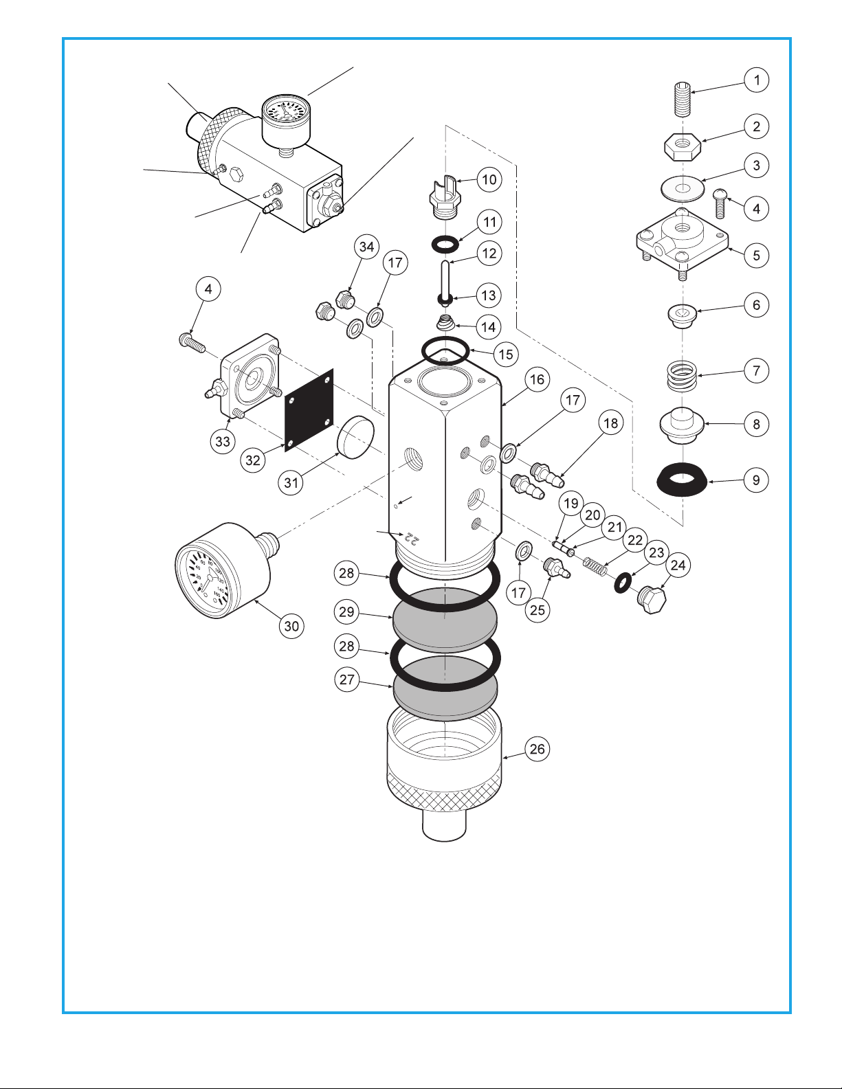
99 MASTER VALVE
127-010 AIR
Batch Stamp
Located Here
Vent Hole
ITEM
1
2
3
4
5
6
7
8
9
10
11
12
PART DESCRIPTION
Set Screw, 1/4-20 x 5/8”.........................
Jam Nut, 1/4-20.......................................
Washer........................................................
Screw, 6-32 x 3/8”....................................
Cap...............................................................
Spring Seat...............................................
Spring.........................................................
Cup Seat.....................................................
Cup Seal......................................................
Seat..............................................................
O-Ring, 008................................................
Stem.............................................................
PART NUMBER
005-024
002-006
003-015
001-041
127-033
127-043
008-008
127-044
017-200
127-026
017-008
127-024
ITEM
13
14
15
16
17
18
19
20
21
22
23
ITEM
24
25
26
27
28
29
30
31
32
33
34
PART DESCRIPTION
O-Ring, 004........................................
Spring..................................................
O-Ring.................................................
Body.....................................................
Plastic Washer, 1/4”........................
Barb, 10-32 x 1/8”............................
O-Ring, 001........................................
Stem....................................................
O-Ring, 003........................................
Spring..................................................
O-Ring, 007.................................. .....
PART DESCRIPTION
Plug...................................................................
Barb, 10-32 x 1/16”......................................
Cap Inlet..........................................................
Filter Element, 100 Micron........................
O-Ring, 018.....................................................
Filter Element, 35 Micron..........................
Gauge...............................................................
Piston................................................................
Gasket..............................................................
Cap....................................................................
Plug...................................................................
PART NUMBER
017-104
008-028
017-018
127-040
003-001
022-010
017-501
127-045
017-103
008-040
017-007
PART NUMBER
020-026
022-009
127-041
119-005
017-022
119-004
026-001
123-014
127-031
123-030
001-001
QTY
1
1
1
8
1
1
2
1
4
3
2
1
QTY
1
1
1
1
5
2
2
1
1
1
1
QTY
1
1
1
1
2
1
1
1
1
1
2
Constant Air Out
Out to Foot Control
ToMaster
On/Off Switch
Regulator Pressure
Adjustment
PressureGauge
Air—80psi
Water—40psi
RemoveBrassKnurledCap
to Replace Filter Element
1010
WaterRelayValve123-000
MASTER VALVE
127-010 WATER
Vent Hole
Batch Stamp
Located Here
ITEM
1
2
3
4
5
6
7
8
9
10
11
PART DESCRIPTION
Set Screw, 1/4”-20 x 5/8”.......................
Jam Nut, 1/4”-20......................................
Washer........................................................
Screw, 6-32 x 3/8”....................................
Cap...............................................................
Spring Seat...............................................
Spring.........................................................
Cup Seat.....................................................
Cup Seal......................................................
Seat..............................................................
O-Ring, 008................................................
PART NUMBER
005-024
002-006
003-015
001-041
127-023
127-043
008-008
127-044
017-200
127-026
017-008
ITEM
12
13
14
15
16
17
18
19
20
21
22
ITEM
23
24
25
26
27
28
29
30
31
32
33
PART DESCRIPTION
Stem....................................................
O-Ring, 004........................................
Spring..................................................
O-Ring.................................................
Body.....................................................
Plastic Washer, 1/4”........................
Barb, 10-32 x 1/8”............................
Plug......................................................
O-Ring, 001........................................
Stem....................................................
O-Ring, 003........................................
PART DESCRIPTION
Spring........................................................
O-Ring, 007......................................... .....
Plug............................................................
Cap Inlet.....................................................
Filter Element, 100 Micron..................
O-Ring, 018...............................................
Filter Element, 35 Micron.....................
Gauge.........................................................
Piston..........................................................
Gasket.........................................................
Cap...............................................................
PART NUMBER
127-024
017-104
008-028
017-018
127-040
003-001
022-010
001-001
017-501
127-045
017-103
PART NUMBER
008-040
017-007
020-026
127-041
119-005
017-022
119-004
126-001
123-014
127-031
123-012
QTY
1
1
1
8
1
1
1
1
1
1
1
QTY
1
1
1
1
1
1
1
4
2
1
1
QTY
1
1
1
1
1
2
1
1
1
1
1
Water Out
Regulator Pressure
Adjustment
PressureGauge
Air—80psi
Water—40psi
RemoveBrassKnurledCap
to Replace Filter Element
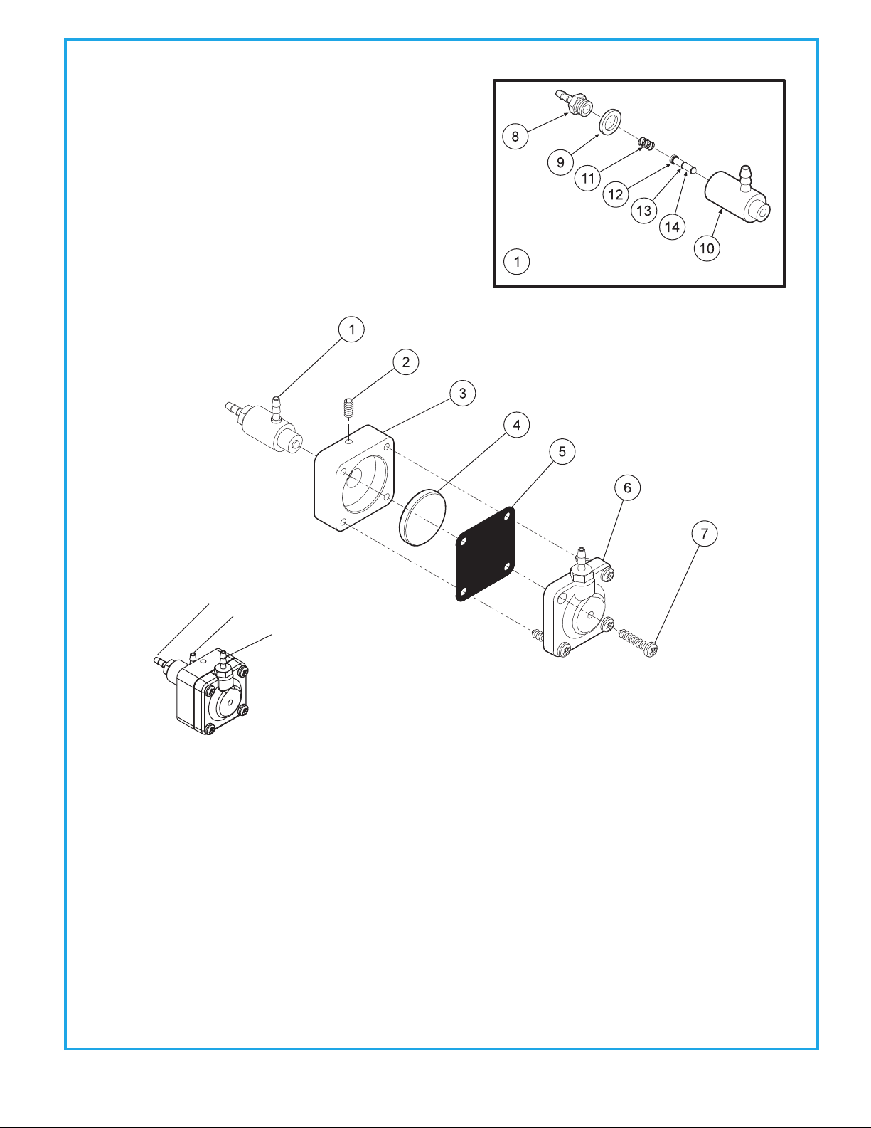
1111 NON-RETRACTION WATER RELAY VALVE
123-000
ITEM
1
2
3
4
5
6
7
8
9
10
11
12
13
14
PART DESCRIPTION
Cartridge Body Assembly.............
Set Screw, 4-40 x 5/8".....................
Body....................................................
Piston..................................................
Diaphragm........................................
Cap.......................................................
Screw, #6 x 1/2"................................
Barb, 10-32 x 1/16".........................
Plastic Washer, 1/4"........................
Valve Body..........................................
Spring.................................................
O-Ring, 002.......................................
O-Ring, 001......................................
Stem...................................................
PART NUMBER
123-018
005-028
123-013
123-014
127-031
123-012
001-267
022-009
003-001
123-017
008-011
017-502
017-501
123-015
QTY
1
1
1
1
1
1
4
1
1
1
1
1
2
1
WaterRelayValve123-000
Air In
Water In
Water Out
1212
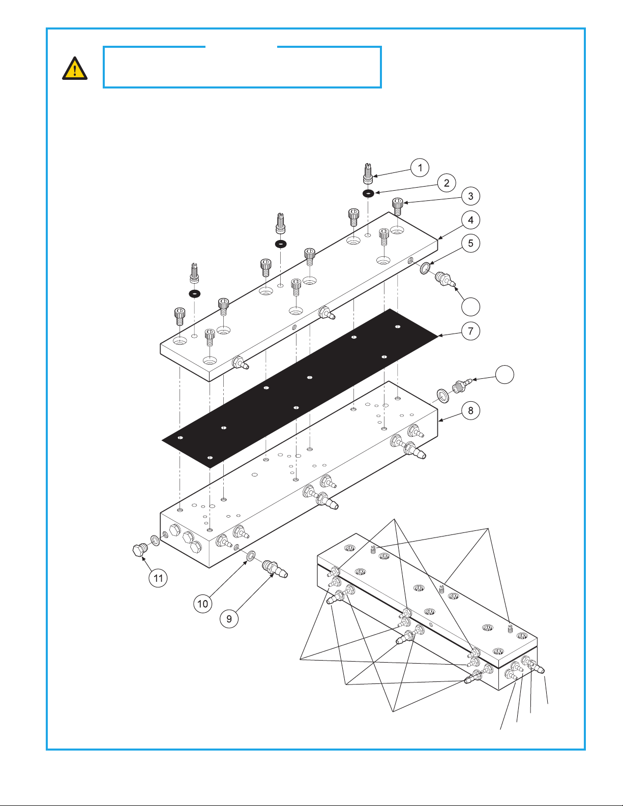
AUTOMATIC HANDPIECE CONTROL BLOCK
125-130
Theautomaticcontrolblockisthecontrolcenterforyourdentalunit.
Individualhandpiecepressureadjustmentsarelocatedontheautoblock.Toadjustthe
pressure to each handpiece:
a. Turnadjustmentscrewclockwise to decrease the handpiece pressure.
b. Turnadjustmentscrewcounter-clockwise to increase the handpiece pressure.
CAUTION
When adjusting the handpiece pressure, do not over-
tighten the screws. Damage may result.
Drive Air In
OuttoGauge
Coolant Air In
Coolant Water In
Coolant Air Out
Drive Air Out
Coolant Water Out
Signal Air In Handpiece Pressure
Adjustment
12
6
ITEM
1
2
3
4
5
6
7
8
9
10
11
12
PART DESCRIPTION
Adjusting Stem...............................
O-Ring, 021 ......................................
Screw, 6-32 x 1/4”...........................
Cap. ....................................................
Plastic Washer. ...............................
Barb, 10-32 x 1/16”.........................
Diaphram ........................................
Body ..................................................
Barb, 10-32 x 1/8”...........................
Plastic Washer, 1/4”.........................
Plug, 10-32 ......................................
Barb, 8-32 x 1/16”...........................
PART NUMBER
125-023
017-021
001-131
125-132
003-030
022-009
125-116
125-131
022-010
003-001
001-001
022-040
QTY
3
3
9
1
3
9
1
1
4
13
4
3
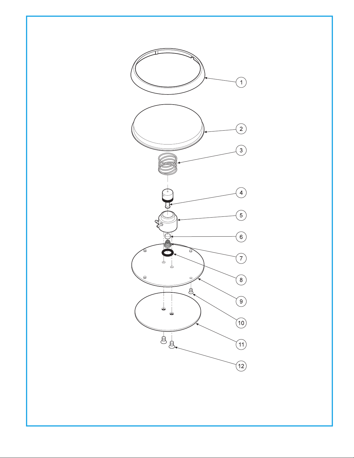
1313 FOOT CONTROL
126-200
ITEM
1
2
3
4
5
6
7
8
9
10
11
12
PART DESCRIPTION
Ring......................................................
Cover....................................................
Spring.................................................
Stem (Includes 017-012 o-ring).....
Body....................................................
Poppet................................................
Spring..................................................
O-Ring, 013........................................
Baseplate...........................................
Screw, 4-40 x 1/4"...........................
Rubber Pad.......................................
Screw, 6-32 x 1/4"...........................
PART NUMBER
126-202
126-201
008-005
126-005
126-004
126-006
008-006
017-013
126-003
001-005
126-007
001-004
QTY
1
1
1
1
1
1
1
1
1
4
1
2
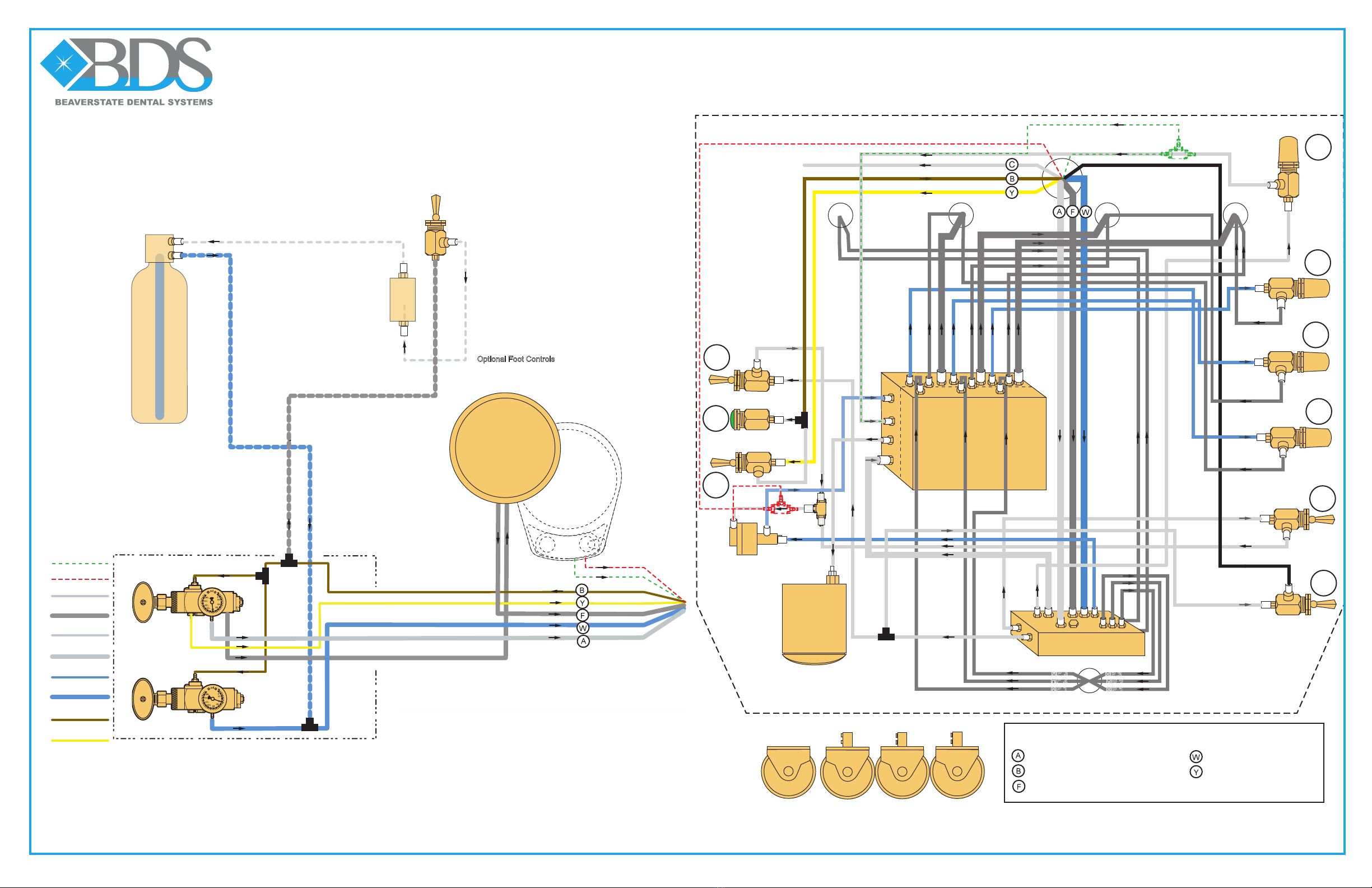
1/4" Clear - Constant Air In
1/8" Brown - On/Off (flow out) to M.V.
1/4" Blue - Water In
1/8" Yellow - On/Off (flow In) from M.V.
Circled letters indicate connection at Junction Box
Junction Box
Air 80 psi
1/4" Gray
1/4" Clear
1/8" Blue
1/8" Clear
1/8" Gray
1/8" Brown
1/8" Yellow
1/4" Blue
1/4" Gray - In From Foot Control
Wet Dry Option
Chip Air Option
Utility Center
S-6300 / S-6307 Unit Head
Water 40 psi
Optional
Water Bottle System
Mini
Regulator
128-016
On/Off
Toggle
120-000
Air Regulator
127-010-A
Water
Regulator
127-010-W
Syringe Handpiece 2 Handpiece 3
Handpiece 1
Unregulated
Foot Control
126-200
Optional Foot Controls
126-133 (Chip Blower)
126-260 (Wet/Dry)
126-203 (Wet/Dry Chip Blower)
Manifold
Block
023-001
HP Pressure
Gauge
026-003
Non-Retracting
Water Relay
Valve
123-000
Shuttle Valve
014-012
Auto Block
125-030
To Syringe To HP 1 To HP 2 To HP 3
HP 1
HP 2
HP 3
1
2
3
5
6
7
8
9
4
HP 1
HP 2
HP 3
Euro 3 Handpiece Automatic control
S-6307

WARRANTY
BDS warranties its product to be free of defects in material and workmanship for SEVEN FULL YEARS from the
date of purchase on all units. Auto-blocks and standard foot controls are covered by a LIFETIME warranty when
factory installed as part of a complete dental system. Upholstery has a TWO YEAR warrany and does not cover
normal wear, stains, cuts or tears. Our LED lights have a FIVE year Warranty and our halogen light has a ONE year
Warranty. Operatory chair motors feature a TEN year warranty. All warranty is limited to repair or replacement
by BDS. Products returned to the factory and determined to be defective will be repaired or replaced free of
charge at discretion of BDS. The warranty does not cover light bulbs, electrical components and trimmed or
installed tubing. BDS reserves the right to void all warranties if any product is installed by other than an authorized
technician. BDS' warranty does not cover damage to any surface finish, including but not limited to, discoloration
or abrasion from cleaners, disinfectants or light sources. No claim for labor or consequential damages will be
allowed. Return items must include a copy of the invoice or packing slip as proof of purchase.

Beaverstate Dental Inc.
115 S. Elliott Rd.
Newberg, OR 97132
800-237-2303
503-538-8756
503-538-2845 Fax
www.beaverstatedental.com
Table of contents
Other BDS Dental Equipment manuals


