BE Ag & Industrial Agri Ease BE-SG24 Application guide

PURCHASE DATE MODEL NO. SERIAL NUMBER
DEALER
OPERATIONS & PARTS MANUAL
STUMP GRINDER
BE-SG24

2 BE-SG24 USER MANUAL
TABLE OF CONTENTS
3IMPORTANT SAFETY INFORMATION
4MACHINE USE AND CARE
5SET-UP PROCEDURES
8OPERATION
13 STORAGE & MAINTENANCE
15 PARTS LIST & EXPLODED ASSEMBLIES

BE-SG24 USER MANUAL 3
IMPORTANT SAFETY INFORMATION
WARNING
Read and understand all instructions. Failure to follow all instructions listed below may result in electric
shock, fire, and/or serious injury.
The warnings, cautions, and instructions discussed in this instruction manual cannot cover all possible
conditions or situations that could occur. It must be understood by the operator that common sense and
caution are factors which cannot be built into this product but must be supplied by the operator.
• All Federal and State laws and any regulation having jurisdiction covering the safety requirements for
use of the machine take precedence over the statements in this manual. Users of this machine must
adhere to such regulations.
• Only people that have read and understood these instructions are permitted to use the stump grinder.
• Inspect the stump grinder and tractor at the beginning of every working day and repair any defects.
• Stop the engine and make sure that the machine will not start accidentally while repairing defects or
performing maintenance.
• Do not disable or remove the stump grinder’s safety devices.
• Always locate and mark buried wires, cables, and pipelines prior to grinding.
PERSONAL SAFETY
• Stay alert, watch what you are doing and use common sense when operating machinery. Do not use
a machine when you are tired or under the influence of drugs, alcohol, or medication. A moment of
inattention while operating machinery may result in serious personal injury.
• Dress properly. Do not wear loose clothing, dangling objects, or jewelry. Keep your hair, clothing, and
gloves away from moving parts. Loose clothes, jewelry, or long hair can be caught in moving parts. Air
vents often cover moving parts and should be avoided.
• Use safety apparel and equipment. Use safety goggles or safety glasses with side shields which comply
with current national standards, or when needed, a face shield. Use a dust mask in dusty work conditions.
This applies to all persons in the work area. Also use non-skid safety shoes, hardhat, gloves, dust collection
systems, and hearing protection when appropriate.
• Do not overreach. Keep proper footing and balance at all times.
• Remove adjusting keys or wrenches before connecting to the power supply or turning on the machine. A
wrench or key that is left attached to a rotating part of the machine may result in personal injury.
• Never conduct any maintenance or make any other adjustments while the tractor engine is running. Always
shut the tractor engine o, remove the ignition key, and keep the engine o before carrying out any of the
following procedures. Consult your tractor’s operator manual for safe shutdown procedures to prevent
accidental ignition.
• Never allow passengers to ride on the stump grinder.

4 BE-SG24 USER MANUAL
MACHINE USE AND CARE
• Always be sure the operator is familiar with proper safety precautions and operation techniques before
using machine.
• Do not force the machine. Machines do a better and safer job when used in the manner for which they are
designed.
• Storing the machine. When the machine is not in use, store it in a dry, secure place or keep it well-covered
and out of the reach of children. Inspect the machine for good working condition prior to storage and
before each use.
• Maintain the machine. It is recommended that the general condition of the machine be examined before
it is used. Keep your machine in good working order by adopting a program of conscientious repair and
maintenance in accordance with the recommended procedures found in this manual. If any abnormal
vibrations or noise occurs, turn the machine o immediately and have the problem corrected before further
use.
• Cleaning. Use a pressure washer to clean the carbide teeth while taking care not to pressure-wash the
bearings as this could introduce water into areas of the machine that may cause malfunction or damage.
• Use only accessories that are recommended by the manufacturer. Accessories that may be suitable for
another machine may create a risk of injury when used on this machine.
• Always operate the machine with all safety devices and guards in place and in good working order. DO
NOT modify or make changes to safety devices. DO NOT operate the machine if any safety devices or
guards are missing or inoperative.
• Never leave the machine running unattended. • Never use the machine to grind anything other than stumps
or for any purpose other than grinding stumps as described in this manual.
BE-SG24 USER MANUAL 5
SET-UP PROCEDURES
TRIMMING THE PTO SHAFT
The stump grinder is shipped with a slip clutch PTO shaft that can be fitted to most Category 1 tractors. The
PTO shaft may need to be trimmed depending on your tractor and configuration. Follow the steps below to
ensure the PTO shaft is correctly fitted to your tractor.
1. Attach the stump grinder to the tractor’s 3-point hitch system. Do not install the PTO shaft.
2. Raise the stump grinder so that the shaft on the tractor is in line with the shaft on the stump grinder.
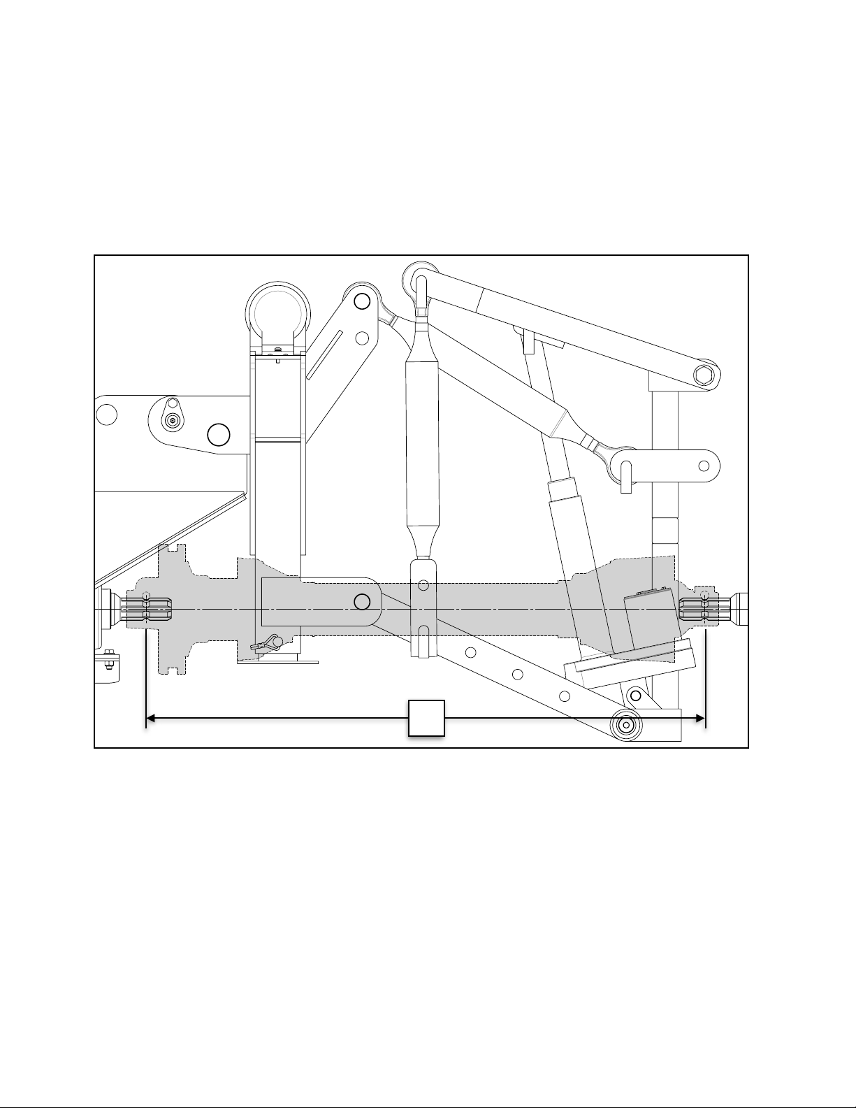
3. Measure the distance between the locking grooves on the splined shafts of the tractor and stump grinder
(Dim A) as shown below:
SET-UP PROCEDURES
TRIMMING THE PTO SHAFT
The stump grinder is shipped with a slip clutch PTO shaft that can be Þtted to most Category 1
tractors. The PTO shaft may need to be trimmed depending on your tractor and conÞguration.
Follow the steps below to ensure the PTO shaft is correctly Þtted to your tractor.
1. Attach the stump grinder to the tractorÕs 3-point hitch system. Do not install the PTO shaft.
2. Raise the stump grinder so that the shaft on the tractor is in line with the shaft on the stump
grinder.
3. Measure the distance between the locking grooves on the splined shafts of the tractor and
stump grinder (Dim A) as shown below:
Page 5of 18
A
Stump Grinder
Tractor

6 BE-SG24 USER MANUAL
4. Verify the distance between the locking pins on the PTO shaft while in the compressed state (Dim B) as
shown in the image below. It should measure 34” (862.5 mm).
4. Verify the distance between the locking pins on the PTO shaft while in the compressed state
(Dim B) as shown in the image below. It should measure 34” (862.5 mm).
5. If Dim A is at least 1” (25 mm) longer than Dim B, the PTO shaft does not require trimming.
It is recommended the shaft not be used if there is less than 6” (150 mm) of overlap
between the two halves of the PTO shaft when the equipment is in the operating position.
6. If Dim B is longer than Dim A, the PTO shaft will require trimming. Use this equation to
calculate the correct amount to trim:
(B - A) + 1 inch = C (Amount to Trim)
7. Once Chas been calculated, trim that amount from BOTH halves of the PTO shaft safety
cover Þrst, then trim the same amount from both shafts. This will ensure the safety cover on
each end remains a few inches back from the ends of the shafts, otherwise PTO shaft
reassembly could be difÞcult.
8. After trimming both halves of the PTO shaft, use a Þle to remove any burrs or sharp edges
and slide the halves back together, ensuring they telescope in-and-out freely. The PTO
shaft is now ready to connect the stump grinder to the tractor for operation.
Page 6of 18
B
Remove burrs from
outer edge of inner
telescoping shaft
after trimming
Remove burrs from
inner edge of outer
telescoping shaft
after trimming
B
5. If Dim A is at least 1” (25 mm) longer than Dim B, the PTO shaft does not require trimming. It is
recommended the shaft not be used if there is less than 6” (150 mm) of overlap between the two halves
of the PTO shaft when the equipment is in the operating position.
6. If Dim B is longer than Dim A, the PTO shaft will require trimming. Use this equation to calculate the
correct amount to trim: (B - A) + 1 inch = C (Amount to Trim)
7. Once C has been calculated, trim that amount from BOTH halves of the PTO shaft safety cover first, then
trim the same amount from both shafts. This will ensure the safety cover on each end remains a few
inches back from the ends of the shafts, otherwise PTO shaft reassembly could be dicult.
8. After trimming both halves of the PTO shaft, use a file to remove any burrs or sharp edges and slide the
halves back together, ensuring they telescope in-and-out freely. The PTO shaft is now ready to connect
the stump grinder to the tractor for operation.
BE-SG24 USER MANUAL 7
FLYWHEEL TOOTH TORQUING
Prior to each operation, ensure all 34 teeth are torqued to 160 ft•lb (215 N•m) using a torque wrench with a
24 mm socket.
FLYWHEEL TOOTH TORQUING
Prior to each operation, ensure all 34 teeth are torqued to 160 ft•lb (215 N•m) using a torque
wrench with a 24 mm socket.
Page 7of 18

8 BE-SG24 USER MANUAL
OPERATION
PRE-START CHECKLIST
1. Prior to operation, ensure all 34 teeth are torqued to 160 ft•lb [215 N•m] using a torque wrench with a 24
mm socket. Refer to the “FLYWHEEL TOOTH TORQUING” section of the operator’s manual.
2. With the stump grinder attached to your tractor, take the appropriate measurements to trim the
PTO shaft. Refer to the “TRIMMING THE PTO SHAFT” section of the operator’s manual for detailed
instructions.
Note: Failure to do so may result in severe damage to the implement and is not covered under
warranty.
3. The stump grinder has multiple bearings fitted with Zerk fittings for greasing. The PTO shaft is fitted with
two (2) Zerk fittings, one on each yoke. The PTO shaft and all bearings com e pre-greased and do not
require greasing on initial start up. Refer to the“M AINTENANCE” section of the operator’s manual for
detailed maintenance instructions.
4. Read the “STUMP GRINDING PROCEDURE” section of the operator’s manual before operating the
stump grinder. It is important to grind stumps correctly to ensure optimal grinding performance and safe
operation.
START UP
WARNING
To avoid death or serious injury, do not grind stumps containing embedded foreign objects such as nails,
wire, metal fragments, etc.
1. Wear heavy-duty work gloves, ANSI-approved goggles behind a full-face shield, steel-toed work boots,
and a dust mask.
2. Securely attach the stump grinder to the tractor’s 3-point hitch system and install the PTO shaft.
3. Prior to each daily use, check all 34 teeth and ensure they are not loose, missing, or damaged, and are
torqued to the proper specification. Torque any undamaged loose teeth to 160 ft lb (215 NM) using a
torque wrench with a 24 mm socket.
STARTUP
1. Wear heavy-duty work gloves, ANSI-approved goggles behind a full face shield, steel-toed
work boots, and a dust mask.
2. Securely attach the stump grinder to the tractor’s 3-point hitch system and install the PTO
shaft.
3. Prior to each daily use, check all 34 teeth and ensure they are not loose, missing, or
damaged, and are torqued to the proper speciÞcation. Torque any undamaged loose teeth
to 160 ft•lb (215 N•m) using a torque wrench with a 24 mm socket.
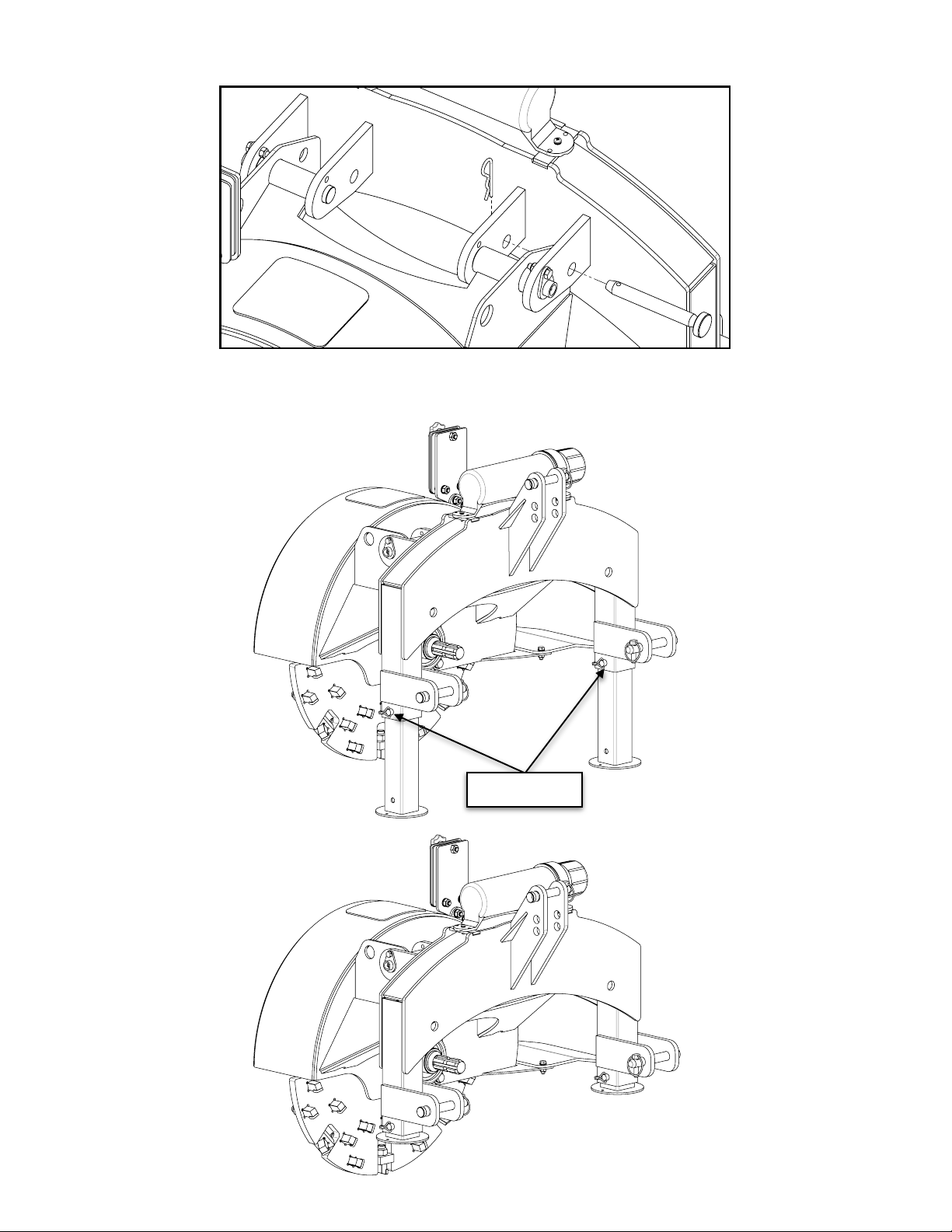
4. Remove the stabilizer pin prior to operation as shown below:
Page 9of 18
To avoid death or serious injury, do not grind stumps containing
embedded foreign objects such as nails, wire, metal fragments, etc.
WARNING!
BE-SG24 USER MANUAL 9
4. Remove the stabilizer pin prior to operation as shown below:
STARTUP
1. Wear heavy-duty work gloves, ANSI-approved goggles behind a full face shield, steel-toed
work boots, and a dust mask.
2. Securely attach the stump grinder to the tractor’s 3-point hitch system and install the PTO
shaft.
3. Prior to each daily use, check all 34 teeth and ensure they are not loose, missing, or
damaged, and are torqued to the proper speciÞcation. Torque any undamaged loose teeth
to 160 ft•lb (215 N•m) using a torque wrench with a 24 mm socket.
4. Remove the stabilizer pin prior to operation as shown below:
Page 9of 18
To avoid death or serious injury, do not grind stumps containing
embedded foreign objects such as nails, wire, metal fragments, etc.
WARNING!
5. Remove the leg locking pins, slide the legs up inside the tubes, and reinstall the locking pins to secure
them in place.
5. Remove the leg locking pins, slide the legs up inside the tubes, and reinstall the locking
pins to secure them in place.
6. Reverse over a tree stump and lower the stump grinder so it will remove 2" (50 mm) per
pass. Always ensure the grinder is cutting properly and not jumping around erratically.
Page 10of 18
Locking Pins

10 BE-SG24 USER MANUAL
6. Reverse over a tree stump and lower the stump grinder so it will remove 2” (50 mm) per pass. Always
ensure the grinder is cutting properly and not jumping around erratically.
7. Once the stump is at ground level, continue to take up to 2” (50 mm) deep passes until the stump and
roots are 4-6” (100-150 mm) below grade. Keep a watch out for foreign objects below the soil like rocks
or buried metal. These can damage or break the teeth resulting in poor grinding performance.
8. During use, it is important to never let the stump grinder sway beyond an angle that will allow the PTO
shaft to separate. Do not operate the stump grinder with less than 6” (150 mm) of overlap between the
two halves of the PTO shaft. If the stump grinder begins to sway, it means either the tractor is advancing
faster than the grinder can remove material or that too much material is being removed per pass. If this
is observed, immediately stop moving forward and position the tractor and stump grinder in a manner so
that it is in the vertical position. Take a slower pass and/or shallower cut if necessary.
7. Once the stump is at ground level, continue to take up to 2” (50 mm) deep passes until the
stump and roots are 4-6” (100-150 mm) below grade. Keep a watch out for foreign objects
below the soil like rocks or buried metal. These can damage or break the teeth resulting in
poor grinding performance.
8. During use, it is important to never let the stump grinder sway beyond an angle that will
allow the PTO shaft to separate. Do not operate the stump grinder with less than 6” (150
mm) of overlap between the two halves of the PTO shaft. If the stump grinder begins to
sway, it means either the tractor is advancing faster than the grinder can remove material or
that too much material is being removed per pass. If this is observed, immediately stop
moving forward and position the tractor and stump grinder in a manner so that it is in the
vertical position. Take a slower pass and/or shallower cut if necessary.
Page 11of 18
Vertical Sway
STUMP GRINDING PROCEDURE
The flywheel spins in a clockwise manner (when facing the rear of the machine) with the eective cutting
area in the lower-left quadrant as shown below:
STUMP GRINDING PROCEDURE
The ßywheel spins in a clockwise manner (when facing the rear of the machine) with the
effective cutting area in the lower-left quadrant as shown below:
Therefore, when grinding a tree stump, always start from the right side of the stump, moving
incrementally to the left, pulling the grinder straight forward through the stump on each pass.
When grinding softwoods like pine, spruce, or poplar, it may be permissible to remove upwards
of 2Ó (50 mm) of material per pass. However, hardwoods like oak, ash, and birch can be much
more dense and the depth of grind may only be up to 1Ó (25 mm). If the chassis is swaying like
described in the previous section, or the grinder is vibrating or bouncing, reduce the depth of
cut or feed rate accordingly.
Page 12of 18
Depth of Grind
Direction of
Grind
Grind
Progression
Effective cutting
area
Left Right

BE-SG24 USER MANUAL 11
Therefore, when grinding a tree stump, always start from the right side of the stump, moving incrementally
to the left, pulling the grinder straight forward through the stump on each pass. When grinding softwoods
like pine, spruce, or poplar, it may be permissible to remove upwards of 2” (50 mm) of material per pass.
However, hardwoods like oak, ash, and birch can be much denser and the depth of grind may only be up
to 1” (25 mm). If the chassis is swaying like described in the previous section, or the grinder is vibrating or
bouncing, reduce the depth of cut or feed rate accordingly.
STUMP GRINDING PROCEDURE
The ßywheel spins in a clockwise manner (when facing the rear of the machine) with the
effective cutting area in the lower-left quadrant as shown below:
Therefore, when grinding a tree stump, always start from the right side of the stump, moving
incrementally to the left, pulling the grinder straight forward through the stump on each pass.
When grinding softwoods like pine, spruce, or poplar, it may be permissible to remove upwards
of 2Ó (50 mm) of material per pass. However, hardwoods like oak, ash, and birch can be much
more dense and the depth of grind may only be up to 1Ó (25 mm). If the chassis is swaying like
described in the previous section, or the grinder is vibrating or bouncing, reduce the depth of
cut or feed rate accordingly.
Page 12of 18
Depth of Grind
Direction of
Grind
Grind
Progression
Effective cutting
area
Left
Right
INCORRECT GRINDING PROCEDURES
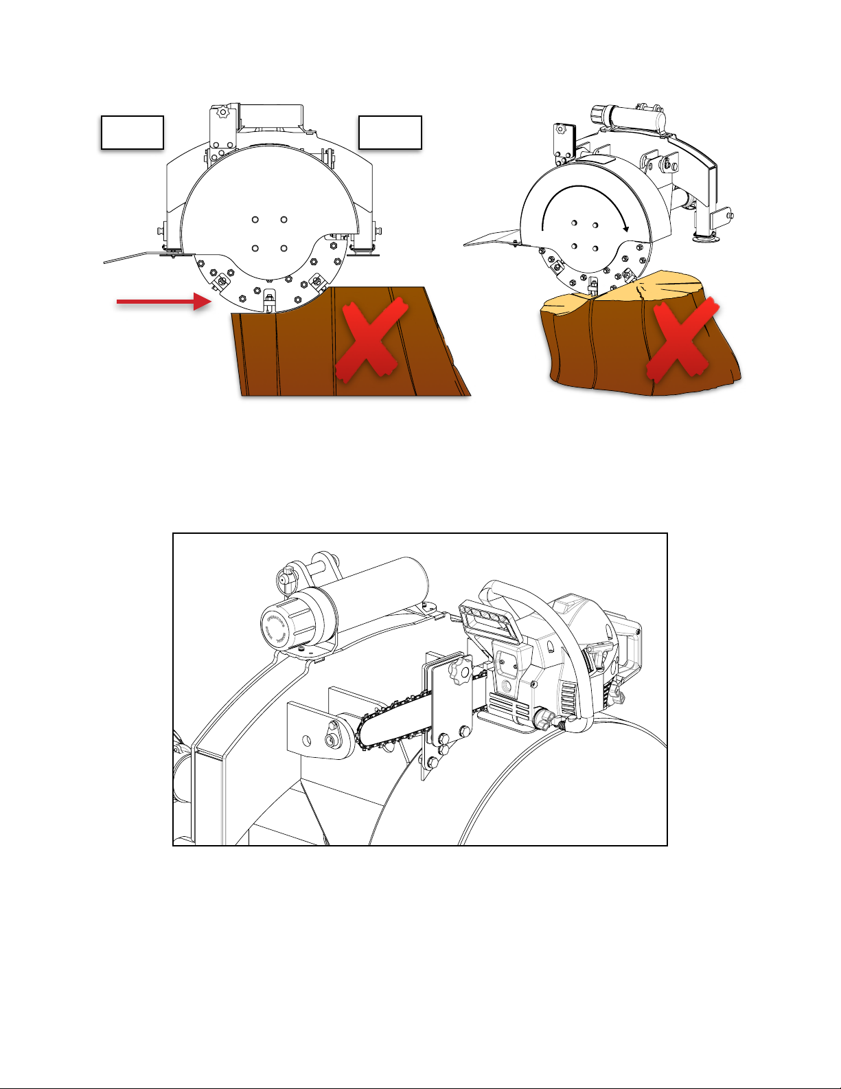
It is critical that the stump grinder is never pulled through the centre of a stump or ground from left-to-right.
This will induce severe vibration and cause the grinder to sway and bounce. It may also damage the machine
and/or break teeth. Follow the directions on the previous page to ensure ecient and safe grinding.
INCORRECT GRINDING PROCEDURES
It is critical that the stump grinder is never pulled through the centre of a stump or ground from
left-to-right. This will induce severe vibration and cause the grinder to sway and bounce. It may
also damage the machine and/or break teeth. Follow the directions on the previous page to
ensure efÞcient and safe grinding.
PULLING THROUGH THE CENTRE
GRINDING LEFT-TO-RIGHT
Page 13of 18
Left
Right
Left Right
12 BE-SG24 USER MANUAL
INCORRECT GRINDING PROCEDURES
It is critical that the stump grinder is never pulled through the centre of a stump or ground from
left-to-right. This will induce severe vibration and cause the grinder to sway and bounce. It may
also damage the machine and/or break teeth. Follow the directions on the previous page to
ensure efÞcient and safe grinding.
PULLING THROUGH THE CENTRE
GRINDING LEFT-TO-RIGHT
Page 13of 18
Left Right
Left
Right
CHAINSAW HOLDER
Use the chainsaw holder only during transport. Always remove the chainsaw from the holder prior to
grinding stumps.
CHAINSAW HOLDER
Use the chainsaw holder only during transport. Always remove the chainsaw from the holder
prior to grinding stumps.
STORAGE
1. Lower both support legs and reinsert the locking pins.
2. Insert the stabilizer pin in either the left or right side of machine. It does not matter which
side is selected.
3. Lower the stump grinder onto a ßat, level surface.
4. Disconnect the PTO shaft.
5. Remove the stump grinder from the tractor’s 3-point hitch system.
Page 14of 18
BE-SG24 USER MANUAL 13
STORAGE
1. Lower both support legs and reinsert the locking pins.
2. Insert the stabilizer pin in either the left or right side of machine. It does not matter which side is selected.
3. Lower the stump grinder onto a flat, level surface.
4. Disconnect the PTO shaft.
5. Remove the stump grinder from the tractor’s 3-point hitch system.
MAINTENANCE
• Proper routine maintenance is critical to operator safety, achieving proper stump grinding results, and
prolonging the life of the machine.
• Before cleaning and/or any maintenance is performed on the stump grinder, always turn o the tractor
engine and disconnect the PTO shaft.
• Inspect the machine before each use for loose nuts and worn cutting teeth and clean any debris that has
built-up.
• After 2 hours of operation, check for loose nuts and worn cutting teeth. Tighten and replace as necessary.
• Grease the bearings and the pivot pins on the main housing as needed before each use. Do not over-
grease the bearings as this can blow out the seals and cause premature bearing failure. Refer to section,
GREASING, for information.
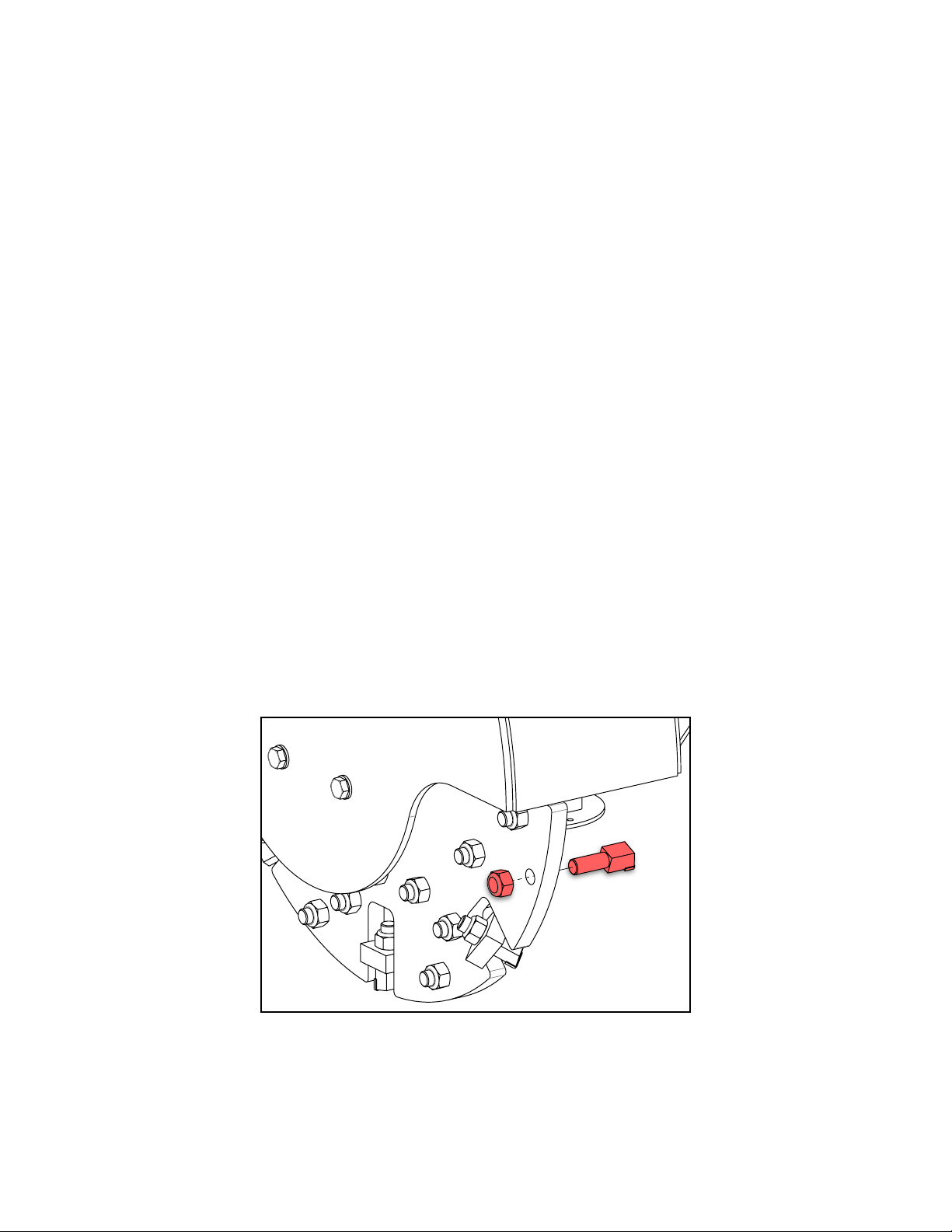
REPLACING TEETH
1. Disconnect the PTO shaft from the tractor and set the stump grinder on a flat, level surface.
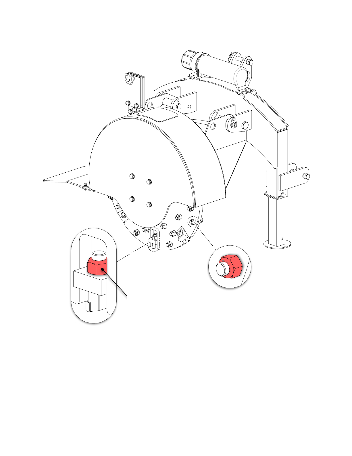
2. Remove the M16 X 1.5 lock nut (fine thread) from the back of the tooth using a 24 mm wrench or socket.
3. Remove the worn cutting tooth while noting its orientation so that the replacement tooth will be installed
in the same manner.
4. Install the replacement tooth and lock nut using a torque wrench set to 160 ft lb (215 NM). Refer to
section FLYWHEEL TOOTH TORQUING for more detail.
MAINTENANCE
•Proper routine maintenance is critical to operator safety, achieving proper stump grinding
results, and prolonging the life of the machine.
•Before cleaning and/or any maintenance is performed on the stump grinder, always turn off
the tractor engine and disconnect the PTO shaft.
•Inspect the machine before each use for loose nuts and worn cutting teeth and clean any
debris that has built-up.
•After 2 hours of operation, check for loose nuts and worn cutting teeth. Tighten and
replace as necessary.
•Grease the bearings and the pivot pins on the main housing as needed before each use.
Do not over-grease the bearings as this can blow out the seals and cause premature
bearing failure. Refer to section, GREASING, for information.
REPLACING TEETH
1. Disconnect the PTO shaft from the tractor and set the stump grinder on a ßat, level surface.
2. Remove the M16 X 1.5 lock nut (Þne thread) from the back of the tooth using a 24 mm
wrench or socket.
3. Remove the worn cutting tooth while noting its orientation so that the replacement tooth will
be installed in the same manner.
4. Install the replacement tooth and lock nut using a torque wrench set to 160 ft¥lb (215 N¥m).
Refer to section FLYWHEEL TOOTH TORQUING for more detail.
Page 15of 18
14 BE-SG24 USER MANUAL
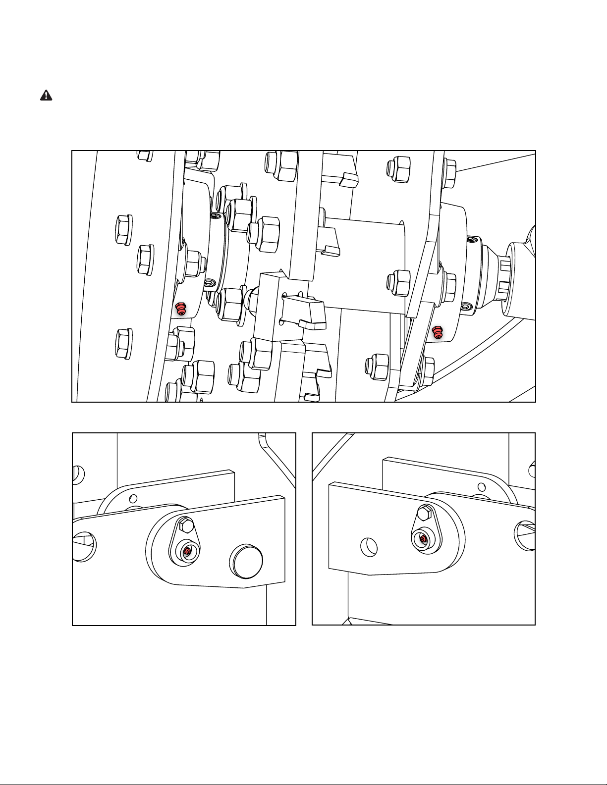
GREASING
The stump grinder has six (6) grease points: two (2) flywheel bearings, two (2) hinge pins, and two (2) on
the PTO shaft. Check each grease point prior to use and add grease as needed.
WARNING
These grease points come pre-greased from the factory. Do not add grease to these points on a new
stump grinder. Over-greasing can damage the bearing seals.
GREASING
The stump grinder has six (6) grease points: two (2) ßywheel bearings, two (2) hinge pins, and
two (2) on the PTO shaft. Check each grease point prior to use and add grease as needed.
**Warning: These grease points come pre-greased from the factory. Do not add grease to
these points on a new stump grinder. Over-greasing can damage the bearing seals.**
Page 16of 18
Flywheel Shaft Bearings (Underside of Flywheel Housing)
Right Pivot Hinge Left Pivot Hinge

BE-SG24 USER MANUAL 15
REF DESCRIPTION QTY
1 HOUSING 1
2 BACK FRAME 1
3 BACK SUPPORT LEG 2
4 FLYWHEEL 1
5 FLYWHEEL SHAFT 1
6 FLYWHEEL TOOTH 34
7 GREASE PIN, 25mm DIA 2
8 GREASE FITTING, STRAIGHT, M6 X 1 TAPERED THD 2
9 DEFLECTOR PLATE 1
10 CHAINSAW HOLDER MOUTING PLATE 1
11 CHAINSAW HOLDER CLAMPING PLATE 1
12 CHAINSAW HOLDER RUBBER MAT 2
13 CHAINSAW REST RUBBER MAT 1
14 KNOB, MULTI-LOBE, 50 mm OD, M10 X 1.5, 40 mm LG 1
15 SPACER, 11 ID X 21 OD X 11 mm LG 2
16 UPPER 3-POINT HITCH PIN, 19 mm DIA X 135 mm LG 1
17 LOWER 3-POINT HITCH PIN, 21 mm DIA X 135 mm LG 2
18 LOCKING PIN, 19 mm DIA X 150 mm LG 1
19 LOCKING PIN, SQUARE, 10 mm DIA, 70 mm USEABLE LG 2
20 LINCH PIN, 10 mm DIA, 38 mm USEABLE LG 3
21 HAIRPIN COTTER PIN, 16-20 mm CLEVIS, 4 mm WIRE DIA 1
22 MANUAL TUBE 1
23 TORQUE ADAPTER, 1/2 in DRIVE, 12-POINT 24 mm 1
24 PTO SHAFT, TRIMMABLE, 36-44 in [914-1121 mm] 1
24.1 COVER/RETAINING CLIP KIT 1
COVER/RETAINING CLIP KIT, EU -
24.2 COVER/RETAINING CLIP KIT 1
24.3 LOCKING PIN KIT 1
FLANGE BEARING, SQ, 4-BOLT, UCF210, 50 mm BORE, 111 mm C-C 2
26 HEX BOLT, M8 X 1.25, 25 mm LG 5
27 HEX BOLT, M10 X 1.5, 30 mm LG 2
28 HEX BOLT, M10 X 1.5, 45 mm LG 2
29 HEX BOLT, M12 X 1.75, 45 mm LG 8
30 SCREW, PPH, M5 X 0.8, 20 mm LG 2
31 SHCS, M16 X 2, 60 mm LG 4
32 FLAT WASHER, M5 2
33 FLAT WASHER, M8 3
34 FLAT WASHER, M10 8
35 FLAT WASHER, M12 8
36 FLAT WASHER, M16 4
37 SPLIT LOCK WASHER, M5 2
38 LOCK NUT, M8 X 1.25 5
39 LOCK NUT, M10 X 1.5 4
40 LOCK NUT, M12 X 1.75 8
41 LOCK NUT, M16 X 1.5 34
42 LOCK NUT, M16 X 2 4
PARTS LIST
Highlighted rows indicate components exclusive to European markets.

16 BE-SG24 USER MANUAL
EXPLODED ASSEMBLIES
COMPLETE ASSEMBLY
Page 18of 18
;
;
;
;
;
;
;
;
;
;
;
;
;
;
;
;
;
;
;
;
;
;
;
;
;
;
;
;
;
;
;
;
;

BE-SG24 USER MANUAL 17

18 BE-SG24 USER MANUAL
PHONE: 604-850-7770
FAX: 604-850-7774
TOLL FREE PHONE: 1-877-588-3311
TOLL FREE FAX: 1-800-665-7334
BRABEREQ.COM
WGSALES@BRABEREQ.COM
Other BE Ag & Industrial Grinder manuals


