BE Ag & Industrial AGRI EASE 81.200.004 Application guide
81.200.004
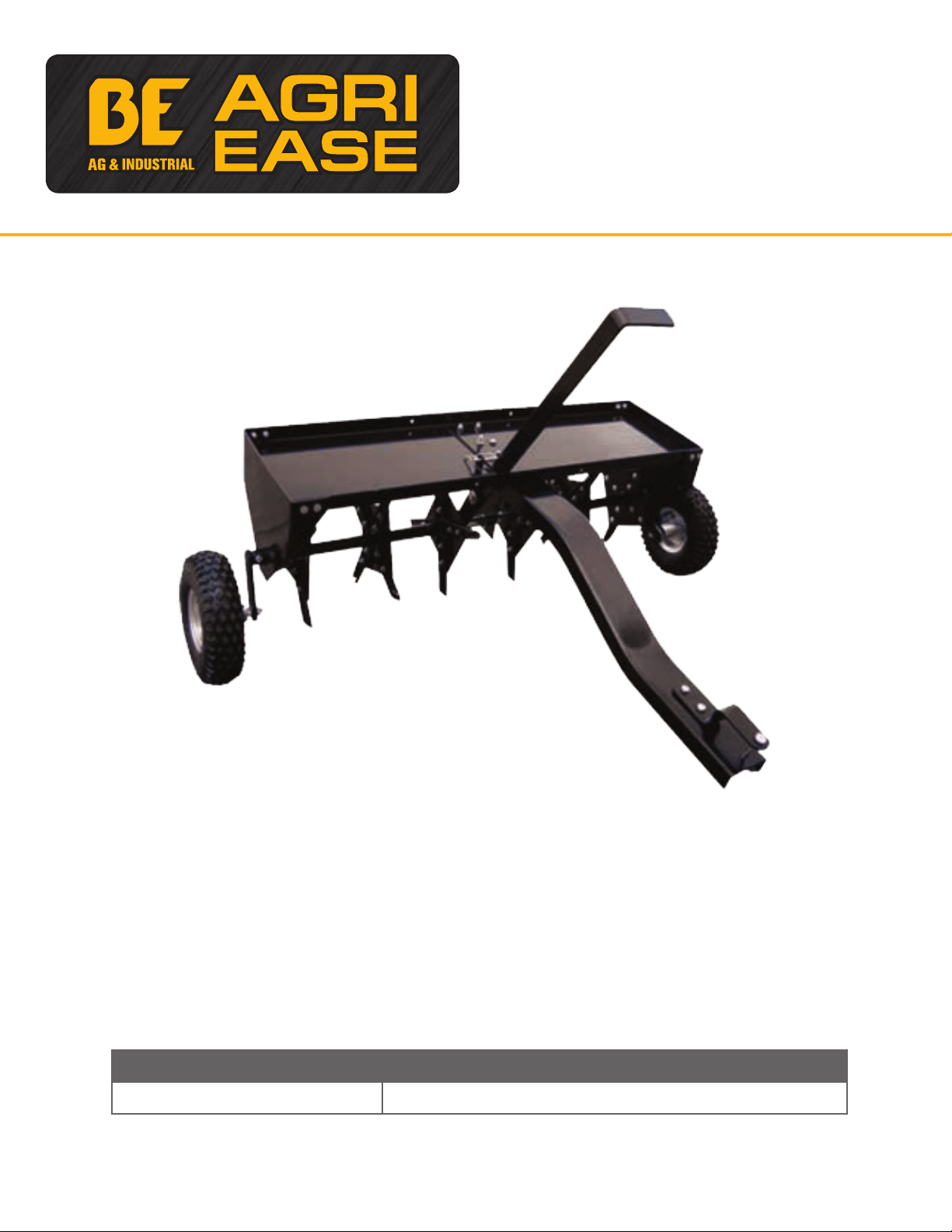
40” Trail Aerator
Operations & Parts Manual
Purchase Date Dealer

Look for this Symbol to point out important safety precautions.
It means ATTENTION! Become Alert! Your safety is involved.
RULES FOR SAFE OPERATIONS 81.200.004
CAUTION: Vehicle braking and stability may be aected with the
addition of an accessory or an attachment. Be aware of changing
conditions on slopes.
Remember, any power equipment can cause injury if operated improperly or if the user does not understand
how to operate the equipment.
Exercise caution at all times when using power equipment.
1. Read this owners manual carefully for operating and service instructions before attempting to assemble or
operate this equipment this equipment. Be thoroughly familiar with the proper use of this equipment.
2. Read the vehicle owners manual and vehicle safety rules and know how to operate the vehicle before
using this equipment.
3. Never allow children to operate the tractor or plug aerator attachment, and do not allow adults to operate
without proper instructions.
4. This aerator attachment has sharp knife points. Always handle with care and wear substantial foot wear
when operating this aerator.
5. Do not allow anyone to ride or sit on plug aerator attachment frame or on towing vehicle.
6. Keep the area of operation clear of all persons, particularly small children and also pets.
7. Always begin with the transmission in first (low) gear and engine at low speed and gradually increase
speed as conditions permit.
8. The vehicle braking and stability may be aected with the attachment of this equipment. Be aware of
changing conditions on slopes. STAY OFF STEEP SLOPES.
9. Always operate up and down a slope, never across the face of slope.
10. This equipment should be operated at reduced speed on rough terrain, along creeks and ditches and on
hillsides, to prevent tipping and loss of control. Do not drive too close to a creek or a ditch.
11. Do not this equipment on a highway or any other public thoroughfare.
12. Follow the maintenance instructions as outlined in this owner’s manual.
CARTON CONTENTS
Ref# Description
1Tray
2 Middle Brace
3 End Plate (2)
4 Lift Handle
5 Tongue
6 Shaft
7 Hitch Bracket
8 Wheels (2)
26 Single Spool (2)
9 Wheel Bracket (3)
10 Double Spool (2)

HARDWARE PACKAGE CONTENTS 81.200.004
REF NO. DESCRIPTION QTY REF NO. DESCRIPTION QTY
Hex Bolt 1/2” X 4-7/16”A 2
Hex Bolt 1/4” x 1-9/16”B 3
Hex Bolt 5/16” x 1-3/16”C 6
Hex Bolt 5/16” x 7/8”D 8
Hex Bolt 5/16” x 1”E 8
Lock PinF 1
R PinG 1
Hitch PinH 1
Hex Nut 1/2”I 2
Lock Nut 1/2”J 2
Lock Nut 5/16”K 22
Flat Washer Ø8M 12
Flat Washer Ø20P 4
Spacer 1/4” LongQ 8
Spacer Tube 1.61” LongR 1
Spacer Tube 0.79” LongS 1
Lock Nut 1/4”T 3
Spacer Tube 2.36” LongU 1
Shoulder SpacerV 1
Spacer Tube 2.76” LongW 1

ASSEMBLY INSTRUCTIONS 81.200.004
Recommended Tools for Assembly
2 each - Combination Wrenches 7/16”, 1/2” & 3/4”
1 - Adjustable Wrench - Medium Size
1 - Medium Size Pliers
Before assembling the aerator, lay out all the parts and hardware as shown on previous pages.
Step 1: Attach Wheel Bracket to Axle Shaft
1. Attach one wheel bracket to the middle hole of the axle shaft. Note the wheel bracket ring should point
towards the shortest side of the axle. See Fig. 1. Attach the wheel bracket using a 1/4” x 1-9/16”
Hex Bolt and a 1/4” Hex Lock Nut. Do not fully tighten.
2. Next, insert from the short side of the axle a 5/16” x 1-3/16” Hex Bolt into the hole on the wheel bracket
closest to the axle. (Smaller hole) attach 5/16” Hex Lock Nut to the bolt. Do not fully tighten until later
step. See Fig 1.
Step 2: Assemble Short Side of Axle Shaft
Assembly below items onto short side of the axle shaft in
the following order. Take note of the direction of plugger
knives in Fig.2.
1. Start with one double spool (knives facing outward).
2. Single spool (knives facing outward).
3. 2.36” Long Spacer
4. Ø20 Flat Washer
CAUTION: Points of aerator knives are sharp! Exercise caution
at all times while assembling and using the aerator.
ASSEMBLY INSTRUCTIONS (CONT.) 81.200.004
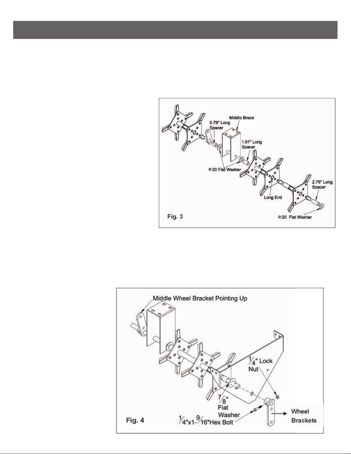
Step 3: Assemble Long Side of Axle Shaft
Assemble these items onto Long Side of the axle shaft in the following order. Take note of the direction of
plugger knives in Fig. 3.
IMPORTANT! Be sure top bracket of Middle Brace faces short end of axle
1. Start with 0.79” spacer tube.
2. Ø20 flat washer
3. Middle Brace
4. Ø20 Flat Washer
5. 1.61” Spacer Tube
6. Double spool assembly (knives facing inward)
7. Single spool assembly
8. 2.76” spacer tube
9. Ø20 flat washer
Step 4: Attach End Plates & Wheel Bracket
Start by rotating the wheel bracket in the middle of the axle shaft so it is pointing upward. Next, attach an
End Plate to one side, followed by a Ø20 Flat Washer and a wheel bracket. Note in Fig 4, Wheel bracket ring
faces inward. Fasten wheel bracket to axle shaft using 1/4” x 1-9/16” Hex Bolt and 1/4” Lock Nut.
Fully tighten connection. Repeat for opposite side.
1. End plates
2. Wheel Brackets
3. Hex Bolts 1/4” x 1-9/16”
4. Lock Nut 1/4”
This manual suits for next models
1
Table of contents
Popular Lawn And Garden Equipment manuals by other brands

Sunforce
Sunforce SOLAR user manual

GARDEN OF EDEN
GARDEN OF EDEN 55627 user manual

Goizper Group
Goizper Group MATABI POLMINOR instruction manual

Rain Bird
Rain Bird 11000 Series Operation & maintenance manual

Cub Cadet
Cub Cadet BB 230 brochure

EXTOL PREMIUM
EXTOL PREMIUM 8891590 Translation of the original user manual


Vertex
Vertex 1/3 HP Maintenance instructions

GHE
GHE AeroFlo 80 manual

Land Pride
Land Pride Post Hole Diggers HD25 Operator's manual

Yazoo/Kees
Yazoo/Kees Z9 Commercial Collection System Z9A Operator's & parts manual

Premier designs
Premier designs WindGarden 26829 Assembly instructions

Snapper
Snapper 1691351 installation instructions