BE Ag & Industrial Agri Ease BE-LS35TLE270GX Application guide

BE-LS35TLE270GX
35 Ton Log Splitter
Operations & Parts Manual
Purchase Date Dealer

To The Owner
Thank you for purchasing your Log Splitter. It was carefully engineered to provide excellent performance
when properly operated and maintained.
Please read this entire manual prior to operating the equipment.
It instructs you how to safely and easily set up, operate and maintain your machine. Please be sure that you,
and any other persons who will operate the machine, carefully follow the recommended safety practices at
all times. Failure to do so could result in personal injury or property damage.
All information in this manual is relative to the most recent product information available at the time of printing.
Review this manual frequently to familiarize yourself with the machine, its features and operation.
Please be aware that this Operator’s Manual may cover a range of product specifications for various models.
Characteristics and features discussed and/or illustrated in this manual may not be applicable to all models.
We reserve the right to change product specifications, design and equipment without notice and without
incurring obligation.
All the power testing information used to establish the power rating of the engine equipped on this machine
can be found at the engine manufacturer’s manual or website. If you have any problems or questions
concerning the machine, phone an authorized service dealer.
Throughout this manual, all references to right and left side of the machine are observed from the
operating position. The engine manufacturer is responsible for all engine-related issues with regards to
performance, power-rating, specifications, warranty and service. Please refer to the engine manufacturer’s
Owners Manual packed separately with your machine for more information.
If you have any diculty assembling this product or have any questions regarding the controls, operation or
maintenance of this machine, please contact your local dealer.
INTRODUCTION BE-LS35TLE270GX

IMPORTANT SAFETY INFORMATION BE-LS35TLE270GX
WARNING: Read and thoroughly understand all instructions in this manual and on safety decals before
assembling or operating this log splitter. Failure to do so may cause injury or death. Do not allow anyone to
operate this log splitter who has not read this manual. As with all power equipment, a log splitter can be
dangerous if assembled or used improperly. Do not operate this log splitter if you have any questions
concerning safe operation. To get answers to any questions, call your local dealer.
Si no entiende ingles, se prefiere que busque algiuen que interprete las instrucciones para usted.
The following signal words and meanings are intended to explain the levels of risk associated with this product.
WARNING: CALIFORNIA PROPOSITION 65 states that engine exhaust, some of its constituents
and certain components contain or emit chemicals known to the State of California to cause cancer
and birth defects or other reproductive harm. For more information, please go to:
www.P65Warnings.ca.gov.com
This SAFETY ALERT SYMBOL identifies important safety messages in this manual.
Failure to follow this important safety information may result in serious injury or death.
DANGER! This machine was built to be operated according to the safe operation practices in
this manual. As with any type of power equipment, carelessness or error on the part of the operator
can result in serious injury. This machine is capable of amputating hands and feet and throwing debris.
Failure to observe the following safety instructions could result in serious injury or death.
DANGER indicates a hazardous situation which,
if not followed, will result in serious injury or death.
WARNING indicates a hazardous situation which,
if not avoided, could result in serious injury or death.
CAUTION indicates a hazardous situation which,
if not avoided, could result in minor to moderate injury.
NOTICE is important information about the proper use
of your machine. Failure to follow this instruction could
result in damage to your machine or property.

SAFETY DECALS BE-LS35TLE270GX
Make sure that all safety warning decals are in good condition and legible. Always replace missing or
defaced decals. Contact your local dealer if any decals are worn or missing.

SAFETY SYMBOLS BE-LS35TLE270GX
This page depicts and describes safety symbols that may appear on this product. Read, understand and
follow all instructions on the machine before attempting to assemble and operate.
WARNING! Your Responsibility - Restrict the use of this power machine to persons who read,
understand and follow the warnings and instructions in this manual and on the machine.
SAVE THESE INSTRUCTIONS!
SYMBOL DESCRIPTION

TRAINING BE-LS35TLE270GX
• Read, understand and follow all instruction on the machine and in the manual(s) before attempting to
assemble and operate. Keep this manual in a safe place for future and regular reference and for ordering
replacement parts.
• Be familiar with all controls and their proper operation. Know how to stop the machine and disengage
them quickly.
• Never allow children under 18 years of age to operate this machine. Children 16 and over should read and
understand the instructions and safe operation practices in this manual and on the machine and be trained
and supervised by an adult.
• Never allow adults to operate this machine without proper instruction.
• Many accidents occur when more than one person operates the machine. No helpers are allowed to assist
in stacking logs.
• Keep bystanders, pets and children at least 25 feet from the machine while it is in operation.
• Never allow anyone to ride on this machine.
• Never transport cargo on this machine.
• Hydraulic log splitters develop high fluid pressures during operation. Fluid escaping through a pin hole
opening can penetrate your skin and cause blood poisoning, gangrene or death. Give attention to the
following instructions at all times:
• Do not check for leaks with your hand.
• Do not operate machine with frayed, kinked, cracked or damaged hoses, fittings or tuning.
• Stop the engine and relieve hydraulic system pressure by cycling the valve control lever forward to reverse
several times while engine is not running. Return to neutral before repairing or adjusting fittings, hoses,
tubing or other system components.
• Do not adjust the pressure settings of the pump or valve.
• Leaks can be detected by passing cardboard or wood over the suspected areas. Always wear protective
gloves and safety glasses when checking. Look for discoloration of cardboard or wood.
• If injured by escaping fluid, see a doctor immediately. Serious infection or reaction can develop if proper
medical treatment is not administered immediately.
• Keep the operator zone and adjacent area clear for safe, secure footing.
• If your machine is equipped with an internal combustion engine and is intended for use near any
unimproved forest, brush or grass covered land, the engine exhaust should be equipped with a spark arrestor.
Make sure you comply with applicable local, state and federal codes. Take appropriate fire fighting equipment
with you.
WARNING! Never use this log splitter for any purpose other than splitting wood.
It is designed for this use only. Any other use can cause serious injury or death.

PRE-OPERATION BE-LS35TLE270GX
• BEFORE operating this log splitter, make sure that you wear safety gear such as goggles or safety glasses,
steel toed shoes and tight fitting gloves (without loose cus or draw strings). Always wear a protective
hearing device when operating this log splitter.
• NEVER wear loose clothing or jewelery that can be caught by moving parts of the log splitter. Keep clothing
and hair away from all moving parts when operating this log splitter.
• Check all safety guards and shields to be sure they are in the proper position. Never operate with safety
guards, shields or other protective features removed.
• Make sure machine is on flat, dry, solid ground before operating.
• ALWAYS operate your log splitter in an open area. (Exhaust fumes contain carbon monoxide which can be
deadly when inhaled).
• ALWAYS operate your log splitter in daylight or under good artificial light.
• ALWAYS operate your log splitter on level ground. (Operating on a slope could cause the log splitter to
roll over or cause logs to fall o).
• ALWAYS block wheels to prevent unintended movement.
• ALWAYS lock beam in either the horizontal or vertical position.
• ALWAYS keep the work area clean. Remove split wood from around the log splitter immediately so that
you don't stumble over it.
• Check all nuts, bolts and hydraulic fittings are tight to be sure the equipment is in safe working condition.
• Both ends of the log should be cut as square as possible to help prevent the log form riding out of the
splitter during operation. Do not split logs greater than 25 inches in length.
Uneven logs (e.g. knotted, curved, etc.) should not be used.
• ALWAYS check the oil level before you start the log splitter.
• Do not allow familiarity with tools to make you careless. Remember that a careless fraction of a second is
sucient to inflict serious injury.
WARNING! The operation of any power tool can result in foreign objects being thrown into
your eyes, which can result in sever eye damage. Before beginning power tool operation, always
wear safety goggles or safety glasses with side shields and when needed, wear a full face shield
and earplugs too. We recommend a Wide Vision Safety Mask for use over eyeglasses or standard
safety glasses with shields. Always use eye protection which is marked to comply with ANSI187.1

OPERATION BE-LS35TLE270GX
• BEFORE operating this machine, review the safety instructions in the manual. Failure to follow these rules
may result in serious injury to the operator or bystanders.
• NEVER leave this machine unattended with the engine running.
•DO NOT operate machine while under the influence of alcohol, drugs or medication.
• NEVER allow anyone to operate this machine without proper instruction.
• ALWAYS operate this machine with all safety equipment in place and in working condition. Make sure all
controls are operating properly for safe operation.
• When loading a log, always place your hands on the side of the log, not the ends, and never use your foot
to help stabilize a log. Failure to do so may result in crushed or amputated fingers, toes, hand or foot.
• NEVER use your foot, a rope or any extension device to operate the control lever on the valve. Only use hands.
• Use only your right hand to operate the controls.
WARNING! When stabilizing log with left hand, remove your hand when the wedge begins to contact the log,
or serious injury may occur.
• For logs which are not cut square, the least square end of the log should be placed toward the beam and
wedge with the square end toward the end plate.
• When splitting in the vertical position, stabilize the log before moving the control handle. Split as follows:
• Place log on the end plate and turn until it leans against the beam and is stable.
• When splitting extra-large or uneven logs, the log must be stabilized with wooden shims or split wood
placed between the log and end plate or ground.
• NEVER place hands or feet between the log and splitting wedge during forward or reverse stroke as this
could result in serious injury or death.
• NEVER attempt to load the log splitter when the ram or wedge is in motion.
• Always keep fingers away from any cracks that open in the log while splitting. They can quickly close and
pinch or amputate your fingers.
• Keep your work area clean. Immediately remove split wood from around the machine so you don't not
stumble over it.
• NEVER straddle or step over the log splitter during operation. NEVER reach or bend over the log splitter to
pick up a log.
• NEVER try to split two logs on top of each other. NEVER try to cross split a log.
• NEVER operate your log splitter when it is in poor mechanical condition or in need or repair.
• NEVER touch the muer and other hot areas of the engine during operation. Wait until the engines cools down.
• NEVER tamper with the engine to run it at excessive speeds. The maximum engine speed is preset by the
manufacturer and is within safety limits. Refer to the engine owner’s manual for your particular log splitter.
• NEVER move the log splitter while the engine is running. Shut o the engine if you are leaving the log splitter,
even for a short period of time.
• ALWAYS be careful when moving or lifting the log splitter. Get assistance if it feels too heavy to move
by yourself.

Operator Zone
Operator Zone
OPERATION BE-LS35TLE270GX
• ONLY operate the log splitter from the operator zone as shown in the diagram below. The operator has the
safest and most ecient access to the control valve and the beam in this location. Operating the log splitter
in another location can result in serious injury or death.
a. Horizontal Operating Position: Stand on the control lever side of the log splitter and stabilize log
if needed. (See Fig. 1).
b. Vertical Operating Position: Stand in front of the log splitter and stabilize log if needed.
(See Fig. 2).
Fig. 1
Fig. 2

MAINTENANCE SAFETY BE-LS35TLE270GX
1. Stop the engine, disconnect the spark plug and ground it against the engine before cleaning or inspecting.
NEVER perform any service or repair on your log splitter without first removing the park plug wire.
2. Stop the engine and relieve hydraulic system pressure by cycling the valve control lever form forward to
reverse several times while engine is not running. Return it to neutral before repairing or adjusting fittings,
hoses, tubing or other system components.
3. ALWAYS perform all recommended maintenance procedures before using your log splitter.
4. ALWAYS check the level of hydraulic oil and engine oil before operation.
5. ALWAYS periodically check that all nuts, bolts, screws, hydraulic fittings and hose clamps are tight to be
sure equipment is in safe working condition.
6. ALWAYS replace all damaged or worn parts immediately with original equipment manufacturer’s O.E.M.
parts only. Use of parts which do not meet the original equipment specifications may lead to improper
performance and compromise safety.
7. The hydraulic system of your log splitter requires careful inspection along with the mechanical parts.
Be sure to replace frayed, kinked, cracked or otherwise damaged hydraulic hoses or hydraulic components.
8. NEVER check for leaks of hydraulic fluid with your hand. Fluid escaping from small holes can be almost
invisible. Escaping fluid under pressure can have sucient force to penetrate skin causing SERIOUS INJURY
or even DEATH. Leaks can be safely detected by passing a piece of cardboard over the suspected area and
looking for discoloration.
9. NEVER remove the cap from the hydraulic tank or reservoir while the log splitter is running. The tank could
contain hot oil under pressure which could result in serious injury.
10. NEVER adjust the hydraulic valve. The pressure relief valve on your log splitter is preset at the factory.
Only a qualified service technician should perform this adjustment.
11. ALWAYS seek professional medical attention immediately if injured by escaping hydraulic fluid.
Serious infection or reaction can develop if proper medical treatment is not administered immediately.
12. ALWAYS be sure to relieve all pressure by shutting o the engine and moving the valve control handle
back and forth should it become necessary to loosen or remove any hydraulic fitting.
NEVER alter your log splitter in any manner. Such alterations may cause your log splitter to
be unsafe and will void the warranty.
According to the Consumer Products Safety Commission (CPSC) and the U.S. Environmental
Protection Agency (EPA), this product has an Average Useful Life of seven (7) years or 130
hours of operation. At the end of the Average Useful Life have the machine inspected annually
by an authorized service dealer to ensure that all mechanical and safety systems are working
properly and not worn excessively. Failure to do so can result in accidents, injuries or death.

FIRE PREVENTION BE-LS35TLE270GX
• ALWAYS take a Class B fire extinguisher with you when operating this log splitter in dry areas.
• NEVER operate your log splitter near a flame, spark or smoke during operation. Extinguish all cigarettes,
cigars, pipes and other sources of ignition. Hydraulic oil and gasoline are flammable and can explode.
• To avoid personal injury or property damage use extreme care in handling gasoline. Gasoline is extremely
flammable and the vapors are explosive.
• ALWAYS store gasoline in an approved, tightly sealed container and keep away from heating appliances.
Store the container in a cool, dry place.
• When gasoline is spilled on yourself or your clothes, wash your skin and change clothes immediately.
• NEVER refuel the gas tank while the engine is hot or running. Allow the engine to cool before refueling.
• ONLY refuel your log splitter in a clear area with no gas fumes or spilled gas. Never fuel the machine indoors.
• Never overfill the fuel tank. Fill tank to no more than 1/2 inch below bottom of filler neck to provide space
for fuel expansion.
• If gasoline is spilled out, wipe it o the engine and equipment and move machine to another area.
Wait five (5) minutes before restarting the engine.
• ALWAYS replace the gas cap securely. Never remove gas cap while the engine is hot or running.
• To prevent fires, clean debris and cha from the engine and muer areas.
• Allow machine to cool at least ten (10) minutes before storing.
• ALWAYS drain the fuel tank prior to storage to avoid the potential fire hazard.
• Never store the machine or fuel container inside where there is an open flame, spark or pilot light as on a
water heater, space heater, furnace, clothes dryer or other gas appliances.
• If the engine is equipped with a spark arrestor muer, clean and inspect it regularly according to the
manufacturer’s instructions. Replace if damaged.
SPARK ARRESTOR WARNING!
This log splitter is equipped with an internal combustion engine and should not be used on or
near any unimproved forest-covered, brush-covered or grass-covered land unless the engine’s
exhaust system is equipped with a spark arrester meeting applicable local or state laws (if any).
If a spark arrester is used, it should be maintained in eective working order by the operator.
In the state of California, a spark arrester is required by law. Other states may have similar
restrictions. Always follow Federal laws that apply on federal lands. A spark arrester muer is
optional and available as an accessory at your nearest engine dealer. Always check the legal
requirements in your area.

TOWING SAFETY BE-LS35TLE270GX
• NEVER carry any cargo or wood on your log splitter.
• NEVER allow anyone to sit or ride on your log splitter.
• ALWAYS turn the fuel shut o valve on the engine to the “OFF” position before towing the log splitter.
Failure to do so may result in flooding the engine.
• ALWAYS check to make sure the low coupler is adjusted properly each time before towing and after
towing 50 miles.
• ALWAYS check before towing to make sure that the log splitter is correctly and securely attached to the
towing vehicle and that the safety chains are secured to the hitch or bumper of the vehicle with enough slack
to allow turning. Always use a Class 1, 2: ball with this log splitter.
• NEVER exceed weight capacity of ball or load limits of coupler. ALWAYS replace ball or coupler if damaged.
• NEVER exceed 45 mph when towing your log splitter. Towing the log splitter at speeds higher than 45 mph
could result in loss of control, damage to the equipment, or serious injury or death. Adjust towing speed for
terrain and conditions.
• ALWAYS be careful when backing up with your log splitter in tow. It could jackknife.
• ALWAYS allow for added length of your log splitter when turning, parking, crossing intersections and in all
driving situations.
• ALWAYS use safety chains when towing your log splitter.
• Be extra cautious when towing over rough terrain, especially railroad crossings. Avoid sharp turns and steep
angles when towing your log splitter.
• Never attempt to move this machine over hilly or uneven terrain without a tow vehicle or adequate help.
• ALWAYS disconnect your log splitter from the towing vehicle before operating it.
• ALWAYS check all local and state regulations regarding towing, licensing and lights before towing your
log splitter. This machine should not be towed on any street, highway pr public road without checking the
existing federal, state or local vehicle requirements. Any licensing or modifications such as taillights, etc.,
needed to comply, is the sole responsibility of the purchaser. If a “Statement of Origin” is required in your
state, see your local dealer.
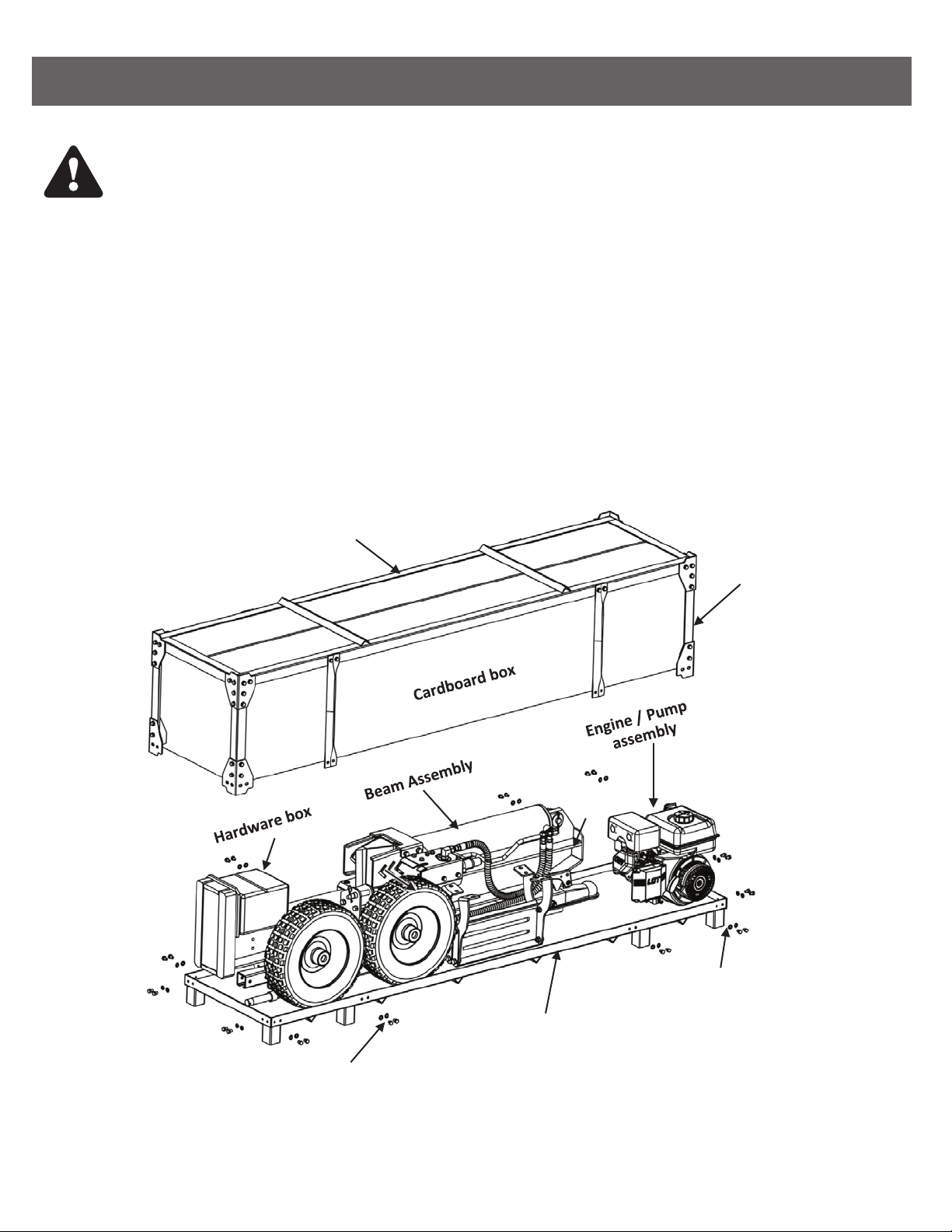
ASSEMBLY & SET-UP INSTRUCTIONS BE-LS35TLE270GX
WARNING! Use extreme caution unpacking this machine. Some components are very heavy
and will require additional people or mechanical handling equipment.
NOTE: All references in this manual to the left or right side and front or back of the log splitter are from the
operating position only. Exceptions, if any, will be specified.
Unpacking tools needed:
• Wrench 13mm
• Scissors of knife
• Pry bar or claw hammer
Step 1: Use a 13mm wrench to remove the bottom bolts and washers securing the crate side frames onto the
crate bottom, then lift up and put away the crate top with the cardboard box together. (See Fig. 3).
Crate Top
Crate Side
Frame
Flat Washer x 24PCS
Hex head bolt x 24PCS
Crate Boom
Fig. 3

Step 2: Remove all loose parts included in the container, e.g. wheels and hardware box.
Step 3: Use scissors or knife to cut and remove the straps securing the parts to the beam or tank assembly,
including tongue assembly and log tray assemblies and put aside these parts for assembly.
NOTE: DO NOT remove the strap securing the hydraulic hoses assemblies to the beam at this time, until
you do the assembly procedure of the hoses.
Step 4: Use scissors or a knife to cut and remove the straps securing the engine/pump assembly to the
crate bottom and then place aside carefully for assembly.
Step 5: Use a pry bar or claw hammer to remove the plywood splinters securing the beam and tank
assemblies on the crate bottom. Take out the two heavy assemblies.
NOTE: Due to the weight/size of the two assemblies, it is recommended two or more adults to assist in lifting
and moving the two assemblies. Lifting tools such as hoist, crane, jack, etc. are also recommended.
Step 6: Inspect all component assemblies, parts and accessories according to the packing list attached in this
manual. Make sure all items listed in the packing list are included and of no shipping damage.
If any parts are damaged or missing, please contact your local dealer assistance.
NOTE: DO NOT discard the packing materials until you have carefully inspected and satisfactorily operated
the tool.
ASSEMBLY & SET-UP INSTRUCTIONS (CONT.) BE-LS35TLE270GX

NOTE: Due to the weight/size of the two assemblies, it is recommended two or more adults to assist in lifting
and moving the two assemblies. Lifting tools such as hoist, crane, jack, etc. are also recommended.
Assembling tools needed:
• Wrench 13mm (x 2)
• Wrench 14mm (x 2)
• Wrench 16, 17, 18, 19, 27, 32 mm (x1 of each)
• Wrench 1/2” (x1)
• Adjustable Wrench (x1)
• Needle Nose Pliers (x1)
• Allen Wrench 3mm (x1)
• Flat Head Screwdriver (x1)
• Soft Faced Hammer (x1)
• Thread Locking Compound (x1)
Step 1: Install the tongue assembly to the reservoir tank. (See Fig. 4).
1. Pull out the spring loaded lock handle of flip-down stand which hold the stand on the tongue, then the stand
will automatically flip down towards the ground and be secured in position.
2. Remove the M10 hardware from the beam support bracket on the tank using a 16mm wrench for bolts and
a 17mm wrench for the lock nuts. Attach the tongue to the reservoir assembly and screw on the hardware
just removed and tighten.
ASSEMBLING BE-LS35TLE270GX
Stand Lock
Flip-down Stand
Fig. 4
REF NO. DESCRIPTION QTY
Reservoir Tank Assembly1 1
Tongue & Flip-Down Stand Assembly2 1
Hex Head Bolt - M10x75 (Beam Support Bracket)3-1 2
Flat Washer - M10 (Beam Support Bracket)3-2 4
Lock Nut - M10 (Beam Support Bracket)3-3 2

Fig. 5
ASSEMBLING (CONT.) BE-LS35TLE270GX
Step 2: Install the two wheels. (See Fig. 5).
1. Raise the reservoir tank assembly o the ground on some blocks before mounting. Remove the plastic
shipping caps from the wheels and position the wheels onto the wheel axles.
2. Screw the castle nuts onto the axles and tighten with an adjustable wrench to seat the bearings.
Then back the castle nuts o one half turn and snug them up to the bearings by hand, so they line up with
the hole in the axle.
3. Insert the split pin into the slot of castle nut and the hole in the axle, then bend the ends of the pin with
needle nose pliers keeping it close to the castle nut so the dust cap fits over it.
4. Tap the dust caps onto the wheel using a soft faced hammer.
REF NO. DESCRIPTION QTY
Pneumatic Tire/Wheel4 2
Castle Nut - 1-1/4 (Hardware Kit #2)5-1 1
Split Pin - Ø4x50 (Hardware Kit #2)5-2 2
Dust Cap (Hardware Kit #2)5-3 2

ASSEMBLING (CONT.) BE-LS35TLE270GX
Step 3: Install the engine/pump assembly to the engine mount plate on the reservoir assembly. (See Fig. 6).
1. Insert a vibration isolator between the engine and the mount plate at each of the four mounting hole
positions.
2. Secure the engine with the hardware, then tighten the hardware using two 13mm wrenches for 25 ton model;
or 16mm wrench on bolts, 17mm wrench on lock nuts for 30/35 ton model.
REF NO. DESCRIPTION QTY
Engine/Pump Assembly9 1
Hex Head Bolt - M8x40 (25/30T) (Hardware Kit #5-1)10-1 4
Flat Washer - M8 (25/30T) (Hardware Kit #5-1)10-2 8
Lock Nut - M8 (25/30T) (Hardware Kit #5-1)10-3 4
Vibration Isolator - Ø9 (25/30T) (Hardware Kit #5-1)10-4 4
O Seal Ring - Ø15*1.9// 2
NOTE: In the Hardware Kit #5-1 or 5-2, you have one (1) O Seal Ring - Ø15*1.9, which is a spare O Ring to
be used in the “Step 6: Connect Hydraulic Hoses” section if you can’t find one sitting in the fitting
slot on the reservoir tank, when you attach the oil return hose (3) to the reservoir tank.
Fig. 6

ASSEMBLING (CONT.) BE-LS35TLE270GX
Step 4: Install the beam assembly. (See Fig. 7).
1. Stand the beam upright on a flat level. Two or more people are recommended to assist with raising and
lowering the beam as it is very heavy. Have a helper support the beam as you perform the following step.
Be sure to keep hands away from any possible pinch points.
2. Remove the clevis pin and spring clip from the beam support bracket on the tank. Position the tongue/tank
assembly so that the beam support bracket is in between the two tabs on the beam.
3. Slide the clevis pin through the aligned holes and secure with the spring clip. You may need another helper
to lift up the tongue for holes to align.
4. Leave the beam in the vertical position for continual assembling steps.
Fig. 7
REF NO. DESCRIPTION QTY
Beam Assembly11 1
WARNING! Take extra care when raising and lowering the beam as it is fairly heavy.
Having a second person assist with raising or lowering the beam is recommended.
Be sure to keep hands away from any possible pinch points.

ASSEMBLING (CONT.) BE-LS35TLE270GX
Step 5: Connect hydraulic hoses. (See Fig. 8).
There are three hydraulic hoses listed below, each of them has one end fixed on the log splitter by manufacturer
and the other open end still needs to be attached. The hoses are labeled on the sends for easy installation.
1. Oil suction hoses 3/4”, labeled as (1), comes from the bottom of the reservoir (or as included in the hardware
kit box). Loosen the hose clamp on the open end of this hose using a flat head screwdriver, then connect the
hose to the fitting on the bottom of the pump, which is also labeled as (1). Tighten the hose clamp.
2. Pump/Valve Connecting hose 1/2”, labeled as (2), comes from the bottom of the valve on the beam assembly.
Screw the open end of this hose onto the fitting on top of the pump, which is also labeled as (2), tighten using
a 27mm wrench or an adjustable wrench.
3. Oil return hose 1/2”, labeled as (3), comes from the top of the valve on the beam assembly. Screw the end
of this hose onto the fitting on the reservoir tank, which is also labeled as (3). Make sure an O-ring Ø15*1.9
sitting inside the fitting slot. Or you could find a spare O-ring in your hardware Kit #5-1 or 5-2. Tighten the
hose using a 32mm wrench or an adjustable wrench.
Valve
Pump
Hose
Clamp
Fig. 8

ASSEMBLING (CONT.) BE-LS35TLE270GX
Step 6: Install the log tray assemblies. (See Fig. 9).
1. Lower the beam to horizontal position. Please refer to “Beam Operating Positions” section in Page 23.
2. Position the log tray frames onto the beam as shown below and secures with the M10 hardware loosely.
3. Tighten the M10 hardware using a 16mm wrench on the bolts and a 17mm wrench on the lock nuts.
Fig. 9
REF NO. DESCRIPTION QTY
Log Tray Assembly12 2
Hex Head Bolt - M10x45 (Hardware Kit #6-1)13-1 4
Flat Washer - M10 (Hardware Kit #6-1)13-2 8
Lock Nut - M10 (Hardware Kit #6-1)13-3 4
Table of contents


