RGBlink TAO 1pro-S User manual

Article NO: RGB-RD-UM-TAO 1pro-S E0002
Version NO: V1.2
User Manual
TAO 1pro-S

©Xiamen RGBlink Science & Technology Co., Ltd.
1
Content
Declarations ..................................................................................................................................3
FCC/Warranty ..................................................................................................................................... 3
Operators Safety Summary ................................................................................................................ 4
Installation Safety Summary ...............................................................................................................4
Chapter 1 Your Product ................................................................................................................5
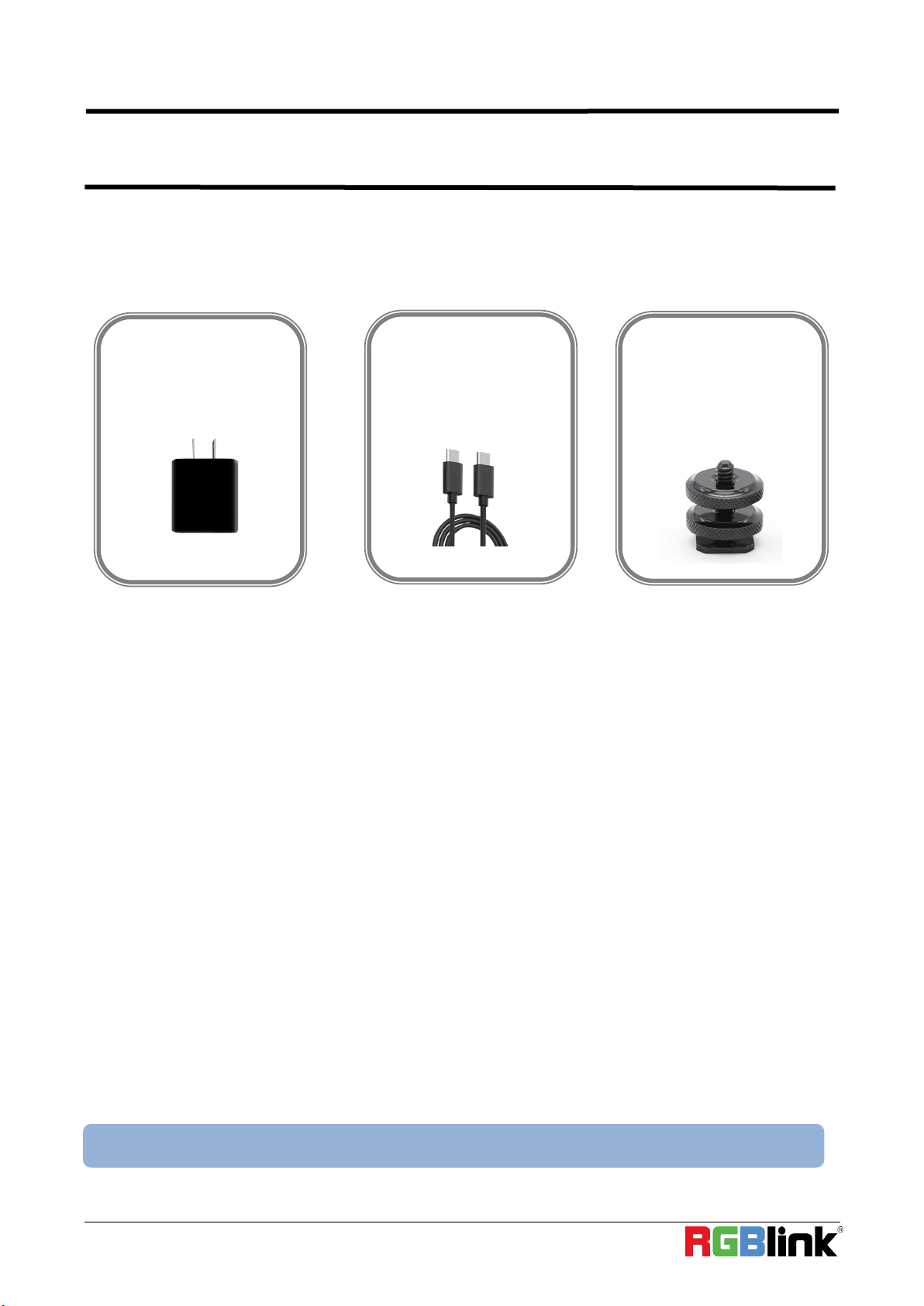
1.1 In the Box ......................................................................................................................................5
1.2 Product Overview .........................................................................................................................6
1.2.1 Key Feature ............................................................................................................................ 6
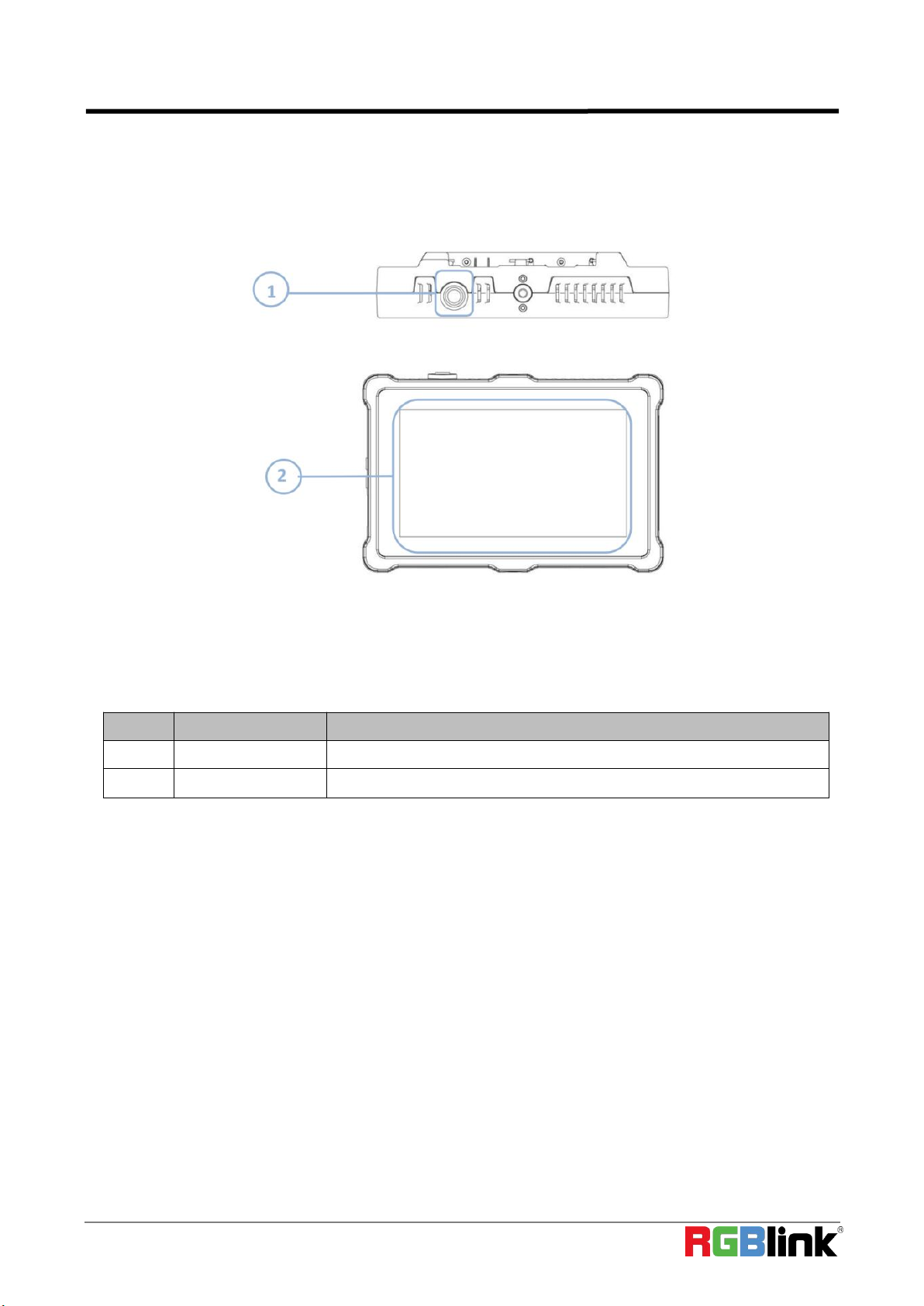
1.2.2 Front Panel .............................................................................................................................7
1.2.3 Interface Panel ....................................................................................................................... 8
1.3 Dimension .....................................................................................................................................9
Chapter 2 Install Your Product ..................................................................................................... 10
2.1 Plug in Power ..............................................................................................................................10
2.2 Connecting Input Signal ..............................................................................................................10
2.3 Connecting HDMI Output ...........................................................................................................11
2.4 Connecting Microphone and External Monitor ......................................................................... 11
2.5 Turn on TAO 1pro-S .....................................................................................................................12
Chapter 3 Use Your Product ......................................................................................................... 13
3.1 Encoding/Decoding Area ............................................................................................................13
3.1.1 NDI Encoding Area ............................................................................................................... 13
3.1.2 NDI Decoding Area/HDMI Output ....................................................................................... 14
3.2 Scroll Area ...................................................................................................................................16
3.2.1 Input Settings .......................................................................................................................16
3.2.2 Audio Meter .........................................................................................................................16
3.2.3 Network ............................................................................................................................... 17
3.2.4 PTZ Control ...........................................................................................................................17
3.2.5 NDI Decoder/Encoder ..........................................................................................................18
3.2.6 Display ..................................................................................................................................19
3.2.7 Fan Control ...........................................................................................................................19
3.2.8 About ................................................................................................................................... 20
3.3 Reminder Area ............................................................................................................................21
3.3.1 Mode Switch ........................................................................................................................ 21
3.3.2 Status Indication .................................................................................................................. 21
3.4 Status Display Area ..................................................................................................................... 22
Chapter 4 Upgrade ...................................................................................................................... 23
Chapter 5 Ordering Codes ............................................................................................................24
5.1 Product Code ..............................................................................................................................24
Chapter 6 Support ....................................................................................................................... 25
6.1 Contact Us .................................................................................................................................. 25

©Xiamen RGBlink Science & Technology Co., Ltd.
2
Chapter 7 Appendix ..................................................................................................................... 26
7.1 Specification ............................................................................................................................... 26
7.2 Battery Installation ..................................................................................................................... 27
7.3 FAQ............................................................................................................................................. 29
7.4 Terms & Definitions .................................................................................................................... 30
7.5 Revision History .......................................................................................................................... 36

©Xiamen RGBlink Science & Technology Co., Ltd.
3
Thank you for choosing our product!
This User Manual is designed to show you how to use this NDI Encoder/Decoder quickly and make use of all the
features. Please read all directions and instructions carefully before using this product.
Declarations
FCC/Warranty
Federal Communications Commission (FCC) Statement
This equipment has been tested and found to comply with the limits for a class A digital device, pursuant to Part 15
of the FCC rules. These limits are designed to provide reasonable protection against harmful interference when the
equipment is operated in a commercial environment. This equipment generates, uses, and can radiate radio
frequency energy and, if not installed and used in accordance with the instruction manual, may cause harmful
interference to radio communications. Operation of this equipment in a residential area may cause harmful
interference, in which case the user will be responsible for correcting any interference.
Guarantee and Compensation
RGBlink provides a guarantee relating to perfect manufacturing as part of the legally stipulated terms of
guarantee. On receipt, the purchaser must immediately inspect all delivered goods for damage incurred during
transport, as well as for material and manufacturing faults. RGBlink must be informed immediately in writing of
any complains.
The period of guarantee begins on the date of transfer of risks, in the case of special systems and software on the
date of commissioning, at latest 30 days after the transfer of risks. In the event of justified notice of compliant,
RGBlink can repair the fault or provide a replacement at its own discretion within an appropriate period. If this
measure proves to be impossible or unsuccessful, the purchaser can demand a reduction in the purchase price or
cancellation of the contract. All other claims, in particular those relating to compensation for direct or indirect
damage, and also damage attributed to the operation of software as well as to other service provided by RGBlink,
being a component of the system or independent service, will be deemed invalid provided the damage is not
proven to be attributed to the absence of properties guaranteed in writing or due to the intent or gross negligence
or part of RGBlink.
If the purchaser or a third party carries out modifications or repairs on goods delivered by RGBlink, or if the goods
are handled incorrectly, in particular if the systems are commissioned operated incorrectly or if, after the transfer of
risks, the goods are subject to influences not agreed upon in the contract, all guarantee claims of the purchaser will
be rendered invalid. Not included in the guarantee coverage are system failures which are attributed to programs or
special electronic circuitry provided by the purchaser, e.g. interfaces. Normal wear as well as normal maintenance
are not subject to the guarantee provided by RGBlink either.
The environmental conditions as well as the servicing and maintenance regulations specified in this manual must be
complied with by the customer.

©Xiamen RGBlink Science & Technology Co., Ltd.
4
Operators Safety Summary
The general safety information in this summary is for operating personnel.
Do Not Remove Covers or Panels
There are no user-serviceable parts within the unit. Removal of the top cover will expose dangerous voltages. To
avoid personal injury, do not remove the top cover. Do not operate the unit without the cover installed.
Power Source
This product is intended to operate from a power source that will not apply more than 230 volts rms between the
supply conductors or between both supply conductor and ground. A protective ground connection by way of
grounding conductor in the power cord is essential for safe operation.
Do Not Operate in Explosive Atmospheres
To avoid explosion, do not operate this product in an explosive atmosphere.
Installation Safety Summary
Safety Precautions
For all product installation procedures, please observe the following important safety and handling rules to avoid
damage to yourself and the equipment.
To protect users from electric shock, ensure that the chassis connects to earth via the ground wire provided in the
AC power Cord.
The AC Socket-outlet should be installed near the equipment and be easily accessible.
Unpacking and Inspection
Before opening product shipping box, inspect it for damage. If you find any damage, notify the shipping carrier
immediately for all claims adjustments. As you open the box, compare its contents against the packing slip. If you
find any shortages, contact your sales representative.
Once you have removed all the components from their packaging and checked that all the listed components are
present, visually inspect the system to ensure there was no damage during shipping. If there is damage, notify the
shipping carrier immediately for all claims adjustments.
Site Preparation
The environment in which you install your product should be clean, properly lit, free from static, and have adequate
power, ventilation, and space for all components.

©Xiamen RGBlink Science & Technology Co., Ltd.
5
Chapter 1 Your Product
1.1 In the Box
USB-C Power Cord
Power Adapter
Double-thread
1/4 Screw
Note: The color of the accessories is subject to actual conditions.

©Xiamen RGBlink Science & Technology Co., Ltd.
6
1.2 Product Overview
TAO 1pro-S is a NDI encoder/ decoder with a 5.5 inch FHD preview display, which also comes with 1
profession-scale SDI input, 1 HDMI 1.3 input and 2 USB 3.0 inputs.
TAO 1pro-S is compatible with standard USB 2.0 and USB 3.0 cameras by UVC protocol.
With a touch panel for finger configuration, TAO 1pro-S is with optional 2 chargeable battery extending its capacity
for outdoor application.
SYSTEM CONNECTION
1.2.1 Key Feature
● NDI encoder and decoder
● 5.5 inch HD touch screen for operation
● Asynchronous rotation of main screen and HDMI output
● 2*UVC inputs,1*HDMI 1.3 input,1*SDI input and 1*HDMI 2.0 output
● HDCP supported
● Sound column
● Type-C interface for charging, support PD protocol
● Compatible with SONY NF970 and Panasonic AG-VBR59MC standard battery socket (no battery install for
standard version)

©Xiamen RGBlink Science & Technology Co., Ltd.
7
1.2.2 Front Panel
No.
Item
Description
1
Power Button
Gently press to turn on,long press 3 seconds to turn off
2
Touch Screen
5.5 inch touch screen for menu control

©Xiamen RGBlink Science & Technology Co., Ltd.
8
1.2.3 Interface Panel
No.
Connectors
Number
Description
1
HDMI IN
1×HDMI IN
Connect to camera and computer
2
SDI IN
1×SDI IN
Connect to camera
3
HDMI OUT
1×HDMI OUT
Connect to external monitor
4
Type C
1×PD Type C
Connect to the power supply
5
Audio
1×MIC IN/LINE OUT
Connect to microphone and earphone
6
LAN
1×RJ45
Gigabit network port
7
USB 2.0
1×USB Type A
Connect to hard disk for recording, and storage up to 2T
8
USB 3.0
2×USB Type A
Connect to USB camera for UVC capture
6
5
4
3
2
7
Right Panel
Left Panel
Bottom Panel
1
8

©Xiamen RGBlink Science & Technology Co., Ltd.
9
1.3 Dimension
Following is the dimension of TAO 1pro-S for your reference:
160.92mm×106mm×36mm

©Xiamen RGBlink Science & Technology Co., Ltd.
10
Chapter 2 Install Your Product
2.1 Plug in Power
When connecting the power supply, please check the power supply standard used in your country/area.
Besides, TAO 1pro-S also supports power supply via batteries. (Battery options in <7.2> for your reference)
2.2 Connecting Input Signal
The camera or device with UVC compliance can be input signal to TAO 1pro-S by USB 3.0 interface.
The camera or device with HDMI 1.3 compliance can be input signal to TAO 1pro-S by HDMI interface.
You can see the resolution of the input signal on the 5.5 inch touch screen when there is active signal plugged in.
Recommend:
TAO 1pro-S is compliance to 1080p50/60 device, once the input signal is interlace or other standard, it is no reco
mmend.
And it is recommended to connect the input sources firstly and then power on TAO 1pro-S after.
Once user change the input signal standard or re-connect the input signal cables, it is strongly recommended to
power off and on TAO 1pro-S to make sure its signal capture correctly.
Notice:
Limitations of TAO 1pro-S are listed as follows :
*1. i signal input and output are not supported;
*2. Reboot is required for signal format modification;
*3. Delay of decoding and encoding is affected by the network.

©Xiamen RGBlink Science & Technology Co., Ltd.
11
2.3 Connecting HDMI Output
You can use an HDMI cable to connect the HDMI output to a monitor with an HDMI input interface, so that you can
monitor the input, output and audio display in real time.
Recommend:
External HDMI 1.3 full HD monitor is recommended.
For external HDMI 2.0 monitor, only once TAO 1pro-S is used as a converter.
2.4 Connecting Microphone and External Monitor
On the left panel of TAO 1pro-S, there is a 3.5mm standard interface which can be directly connected to the
microphone.
You can also use external speakers or headphones to monitor the main output audio signal in real time. Audio
supports 0~60db.

©Xiamen RGBlink Science & Technology Co., Ltd.
12
2.5 Turn on TAO 1pro-S
After TAO 1pro-S is connected to power supply, gently press the power button on the top panel, the device will
enter to the boot interface and enter operation interface.

©Xiamen RGBlink Science & Technology Co., Ltd.
13
Chapter 3 Use Your Product
Once push the power button to power on TAO 1pro-S, the 5.5 inch display will show TAO logo and then
come into the main menu, and once the default input signal is connected, operator can follow the following opera
tions to use TAO 1pro-S.
The main menu of TAO 1pro-S can be divided into four parts: Encoding/Decoding Area, Scroll Area, Reminder
Area and Status Display Area.
3.1 Encoding/Decoding Area
3.1.1 NDI Encoding Area
TAO 1pro-S supports NDI|HX and transmits data in H.264 format.
In NDI Encoding mode, TAO 1pro-S can convert video data from other channels (such as SDI, HDMI, UVC, etc.) into
NDI format and send it to the receiver.
Press the [ NDI Encoder ] icon to enter the interface so as to choose/switch input signal. SDI/HDMI/UVC for you to
choose from.
Decoding Area/HDMI Output
Encoding Area

©Xiamen RGBlink Science & Technology Co., Ltd.
14
Input Signal Status ( Applicable to this user manual):
NDI Status ( Applicable to this user manual):
3.1.2 NDI Decoding Area/HDMI Output
Users can switch decoding function and HDMI output function in the right corner of interface.
3.1.2.1 NDI Decoding Area
If you need to perform NDI Decoding mode, please follow the steps below.
1. --no input signal source
2. --with signal source but not be selected
3. --enabled signal source
1. --no input signal source
2. --with input signal source but not be selected
3. --enabled signal source
4. + --encoding/decoding/HDMI output function be enabled

©Xiamen RGBlink Science & Technology Co., Ltd.
15
1)If DHCP function is closed, you need to set the network of TAO 1pro-S to be the same as decoding NDI source.
(Please refer to 3.2.3 Network for operation.)
2)If DHCP function is operated, please connect TAO 1pro-S to a switcher with IP distribution function. Then TAO
1pro-S can search for NDI sources automatically.
Click [Search] for NDI source selection.
[NDI Searching] in the interface displays its searching status and NDI source list will be shown after searching is
completed.
TAO 1pro-S supports preselection of up to four NDI sources at the same time. Choose signal sources you need and
then click [Confirm].
Users can also click [MORE] in the NDI source interface for re-search.
3.1.2.2 HDMI Output
You can choose the signal to be converted from four input sources (HDMI/SDI/UVC1/UVC2), and the input signal
will be converted to HDMI output format.

©Xiamen RGBlink Science & Technology Co., Ltd.
16
3.2 Scroll Area
The left area of the interface is the Scroll Area, where users can scroll clockwise/counterclockwise to achieve
functions such as Input Settings, Audio Meter, Network, PTZ Control, NDI Decoder/Encoder, Brightness, PVW
Mode, Fan Control, About.
3.2.1 Input Settings
Click [Input] to enter the page.
In this interface, you can select Input Signal, set Input Format and Audio Sampling Rate.
3.2.2 Audio Meter
Gently touch [Audio Meter] to enter the setting interface.
As shown in the pictures above, there are four audio columns in the interface, one HDMI input audio, one 3.5 mm
analog audio input and one 3.5mm analog audio output. Every audio column is divided into left/right channel.

©Xiamen RGBlink Science & Technology Co., Ltd.
17
You can select【Auto】or manually turn on the column by touch the rectangle icon above the column. (Yellow icon
indicates selected one)
3.2.3 Network
Click [Network] to enter the following page.
When DHCP is turned on, the IP Address can be captured automatically.
When DHCP is turned off, you can manually set the IP Address, Netmask and Gateway (The Keyboard interface
will pop up for typing). After setting, click [Enter].
3.2.4 PTZ Control
When there are PTZ cameras connected to TAO 1pro-S, you can control PTZ and Tally light in the menu. Click [PTZ
Control] to enter the following page.

©Xiamen RGBlink Science & Technology Co., Ltd.
18
In the [ PTZ Control ] menu, there are six Views to be selected. After selecting the View, you should first click [Save]
and then [Load].
If you would like to change the default setting, then click [ View 1 ] and adjust the location and zoom manually or
you can turn on [ Auto].
When [ PTZ Control ] is operated, the border of the interface displays TALLY of PTZ (shown as above). Red border
indicates PTZ has been operated; green border indicates connected status of PTZ, but PTZ has not been operated.
Click [ Tally Control ] to choose whether to enable the function. 3 kinds of frame pixel for you to choose from:
mini (10 pixel), mid (20 pixel), max (30pixel). Port Number and IP Address can not be modified.
3.2.5 NDI Decoder/Encoder
Click [NDI Decoder/Encoder] to enter the setting page.
NDI Decoder
Resolution: up to 1920x1080@60
Bitrate: 41000HZ
NDI Type: NDI|HX
NDI Encoder
NDI Channel Name: Edit the name of NDI channel. After setting, click [Enter] to save.

©Xiamen RGBlink Science & Technology Co., Ltd.
19
Device Name: Edit the name of device
Coding Quality: Adjust compression ratio of NDI coding
Connection: Multicast/Unicast optional
If you select Multicast, you can also set Net Mask/ IP Address/TTL. After setting, click [Enter].
3.2.6 Display
Click [Display] to enter the setting page.
In this interface, you can set the brightness of the output, HDMI output resolution. In addition, TAO 1pro-S also
comes with a screen rotation function.
Brightness: 0-100%
HDMI Output: 2K, 4K
Display Rotation: 0°, 180°
3.2.7 Fan Control
Click [Fan Control] to enter the following page.
Table of contents
Other RGBlink Media Converter manuals

RGBlink
RGBlink GX4 User manual

RGBlink
RGBlink M2 User manual

RGBlink
RGBlink MSP326 User manual

RGBlink
RGBlink MSP 210D User manual

RGBlink
RGBlink X14 User manual

RGBlink
RGBlink RGB-RD-UM-X8 E005 User manual

RGBlink
RGBlink FLEX4ML User manual

RGBlink
RGBlink GX4 User manual

RGBlink
RGBlink GX4 User manual

RGBlink
RGBlink VSP 168S User manual

RGBlink
RGBlink VSP 516 Series User manual

RGBlink
RGBlink MVP 8043 User manual

RGBlink
RGBlink D8 User manual

RGBlink
RGBlink VENUS X1 User manual

RGBlink
RGBlink VSP268S User manual

RGBlink
RGBlink M1 User manual

RGBlink
RGBlink MSP 221 User manual

RGBlink
RGBlink VENUS X7 User manual

RGBlink
RGBlink Q Series User manual

RGBlink
RGBlink FLEXpro 8 User manual