Beachside Lighting MB4 12V User manual

MB4 12V
04/2019
LAMP TYPES:
• 12V MR16 GU5.3 bi-pin base; Max. 10W LED, 50W halogen
• LED Module; Max. 12W
800-405-6732
www.BeachsideLighting.com
CSA Listing pending
WARNING — Risk of Electric Shock. Install all luminaires 10 feet (3.05 m) or more from a
pool, spa, or fountain. This xture must be installed in accordance with the National Electric
Code and/or local codes. Failure to do so
may result in serious personal injury or death. Wir-
ing must be done by a licensed electri
cian.
INSTRUCTIONS PERTAINING TO A RISK OF FIRE OR INJURY TO PERSONS
IMPORTANT SAFETY INSTRUCTIONS SAVE THESE INSTRUCTIONS
Lighted lamp is HOT!
WARNING – To reduce the risk of FIRE OR INJURY TO PERSONS:
• Turn off/unplug and allow to cool before replacing lamp.
• Lamp gets HOT quickly! Contact only switch/plug when turning on.
• Do not touch hot lens or faceplate.
• Keep lamp away from materials that may burn.
• Do not touch the lamp at any time. Use a soft cloth. Oil from skin may damage lamp.
• Do not operate the luminaire fitting with a missing or damaged faceplate or lens.
For luminaires equipped with halogen lamps:
This is a low-voltage xture for use with maximum 25A, 15V power units only. A remote
transformer is required. Do not overload the transformer by installing or relamping with high-
er wattage lamps that together exceed the capacity of the transformer. The unit low-voltage
cable shall: a) be protected by routing in close proximity to the luminaire or tting, or next to a
building structure such as a house or deck; b) not be buried except for a maximum 6 inches
(15.2 cm) in order to connect to the main low-voltage cable; and c) have the length cut o
so that it is connected to a connector within 6 inches (15.2 cm) from a building structure, a
luminaire, or tting. Contact Beachside Lighting for low voltage cable and direct burial wire
for use as main secondary wiring.
necessary for power supply wires, using the
Mounting Collar for positioning. Conduit
should stick up above top of concrete 1/4”.
(Figure 1)
6. Fill hole with concrete. Double-check
conduit location with Mounting Collar.
7. Once concrete is set, place Mounting
Collar over conduit and mark locations for
the three mounting holes.
8. Use a 5/8” masonry bit to drill a minimum
2-1/2” deep hole at each marked location
and tap in the supplied lag shields.
9. Secure the Mounting Collar with supplied
3/8” lag screws using a 9/16” socket
wrench.
10. Pull supply wires and verify they are not
energized.
11. Feed the wire leads from the xture through
the top of the BSB Cover, apply threadlock
to the Base threads, and screw the Cover
tightly onto the 1/2” threads in the bottom
of the xture.
12. Use silicone-lled wire nuts to join xture
leads to supply wires. Use silicone or
electrical tape around wire nuts to ensure
proper connection.
13. Slide the xture with the Cover attached
straight down over the Mounting Collar.
14. If the xture is equipped with the Half
Shield, orient the xture so the light shines
in the desired direction. Alternately tighten
the three set screws in the Cover with a
1/8” hex wrench.
INSTALLATION on BRASS SURFACE BOX (BSB)
1. For mounting to concrete, skip to Step 5.
2. When mounting to a wooden surface, use the Mounting Collar to mark locations of the
three mounting screws and hole(s) for the supply wiring.
3. Drill holes for wires as needed and drill pilot holes at the marked screw locations using
a 15/64” drill bit.
4. Secure the Mounting Collar with supplied 3/8” lag screws using a 9/16” socket/wrench.
Proceed to Step 10.
5. Dig a hole at desired location at least 12” diameter x 12” deep and run conduit as
BSB COVER
LAMP OR LED
MODULE
LAMP HOUSING
LAG SHIELDS
BASE
Apply thread-locking
agent (by others) to
male threads.
SET SCREW (x3)
MOUNTING
COLLAR
SET SCREW (x3)
CONDUIT
CONCRETE
MOUNTING COLLAR
TOP VIEW
CONDUIT GUIDES
3/8" HOLES FOR
LAG SCREWS
UNION
LAG SCREWS
LOWER SHAFT
SET SCREW (x3)
Figure 1
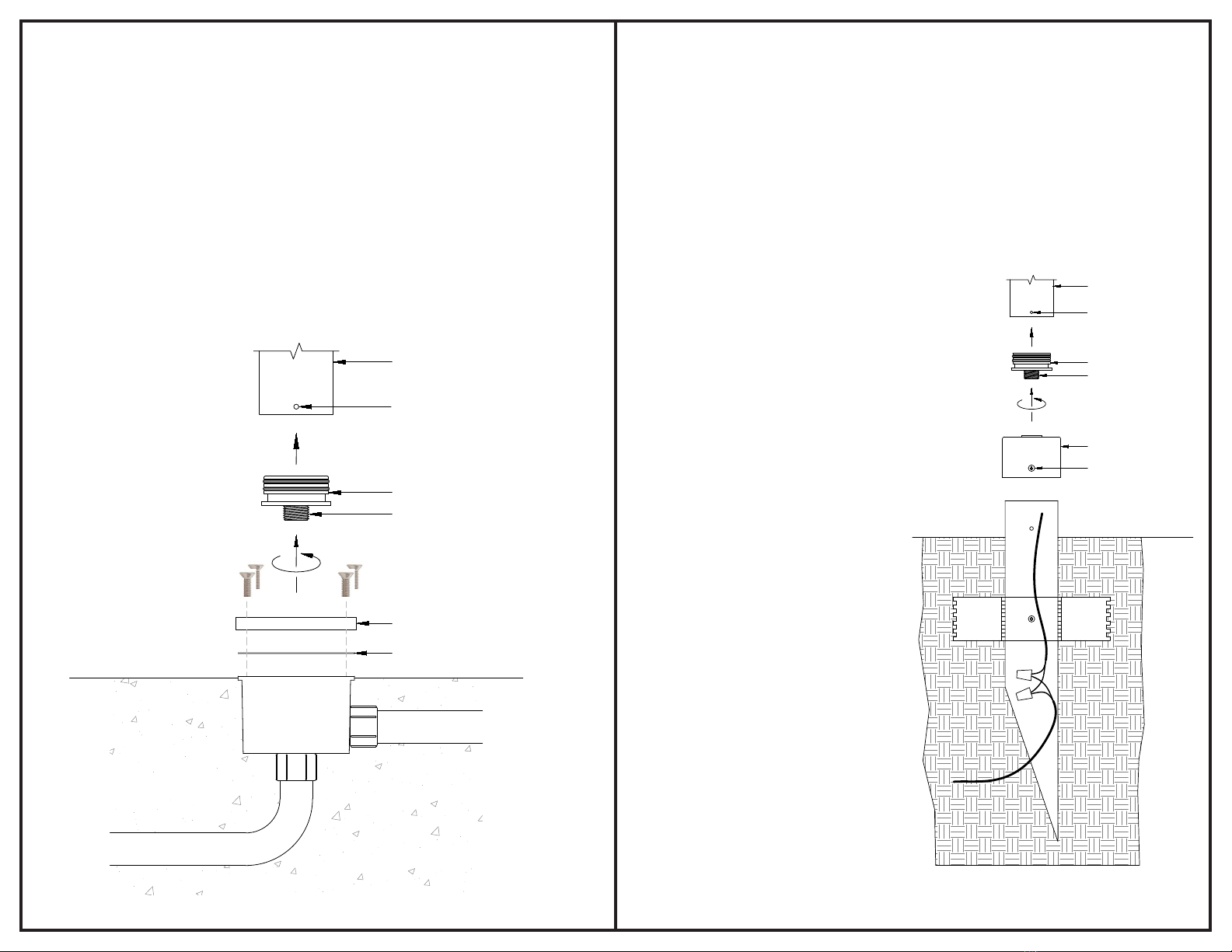
INSTALLATION on JUNCTION BOX (JB)
1. Dig a hole at desired location at least 12” diameter x 12” deep and run conduit as
necessary for power supply wires. Position the Junction Box (JB) so that the bottom of
its Cover will be above grade after the concrete is poured. (Figure 2)
2. Plug unused holes and ensure all ttings are watertight.
3. Fill hole with concrete, making sure JB is level and that its Cover will be above grade.
4. Once concrete is set, remove Cover using a 5/32” hex wrench and pull the supply wires.
Verify they are not energized.
5. Feed the wire leads from the xture through the top of the JB Cover and gasket, apply
threadlock to the Base threads, and screw the Cover tightly onto the 1/2” threads in the
bottom of the xture.
6. Use silicone-lled wire nuts to join xture leads to supply wires. Use silicone or electrical
tape around wire nuts to ensure proper connection.
7. Push the connections into the JB and reattach the Cover/xture assembly.
8. If the xture is equipped with the Half Shield, it can be aimed by loosening the three set
screws at the base of the Shaft (or Lamp Housing if not equipped with a lower Shaft) with
a 3/32” hex wrench. Aim the xture as desired and alternately retighten the set screws.
INSTALLATION on GROUND SPIKE (GS2BC)
1. Dig a hole at desired location roughly 10” diameter x 18” deep and route the supply wires
coming from the power source to the hole, entering it near the bottom. (Figure 3)
2. Remove the Brass Cap from the Ground Spike by removing the screw from the side of
the Cap.
3. Feed the supply wire into the bottom of the Spike and out through the top while placing
the Spike into the hole.
4. Rell the hole while keeping the Spike vertical. Position the Spike so that the bottom of
its Cap will be at grade when the hole is completely lled.
5. Feed the wire leads from the xture
through the top of the Cap, apply
threadlock to the Base threads, and
screw the Cap tightly onto the 1/2”
threads in the bottom of the xture.
6. Use silicone-lled wire nuts to join
xture leads to supply wires. Use
silicone or electrical tape around wire
nuts to ensure proper connection.
7. Feed the wires and connectors into
the top of the Spike while replacing
the Cap/xture assembly onto the
Spike. Align the hole and fasten
the Cap to the Spike with the screw
removed in Step 2.
8. If the xture is equipped with the Half
Shield, it can be aimed by loosening
the three set screws at the base of
the Lamp Housing with a 3/32” hex
wrench. Aim the xture as desired
and alternately retighten the set
screws.
Mounting on ground spike is only recommended for the 9” version of the MB4. Taller versions
require use of the BSB or JB mounting accessories.
LAMP HOUSING
BASE
SET SCREW (x3)
SCREW
BRASS CAP
Apply thread-locking
agent (by others) to
male threads.
LOWER SHAFT
CONDUIT
CONCRETE
JUNCTION
BOX
BASE
Apply thread-locking
agent (by others) to
male threads.
JB COVER
GASKET
SET SCREW (x3)
Figure 2 Figure 3

LAMPING – Integrated LED Module
1. Make sure the power to the xture is o.
2. With the xture still attached, remove the Cap or Cover from the Ground Spike, Junction
Box, or BSB.
3. Disconnect the xture leads from the supply wires.
4. Loosen the three set screws at the bottom of the Lamp Housing with a 3/32” hex wrench
and slide it straight up to remove, exposing the LED Module.
5. If the xture is equipped with a Lower Shaft, loosen the three set screws at its bottom
with a 3/32” hex wrench and slide it up o the Base, pulling the wires up through the red
silicone plug inside the Base. (Figure 1)
6. Unscrew the LED Module 4-5 revolutions to remove it.
7. Carefully press the red silicone plug out the bottom of the Base from the top with a
narrow, blunt object and save to be reinserted later.
8. Feed the lead wires from the new LED Module through the Base (or Union and Lower
Shaft, if equipped, then the Base) and screw the Module down until it bottoms out.
9. Replace the Lamp Housing (and Lower Shaft, if equipped) and alternately tighten the
set screws.
10. Feed the leads through the silicone plug. Carefully slide the plug up the wires and
reinsert the plug back into the Base.
11. Follow the nal three Steps in the appropriate “Installation” section of these instructions
to complete the operation.
This xture has a long-life LED Module that should not need replacement for years. However,
if a Module fails or technology improves and a new one is desired, replacements are available
from Beachside Lighting (808-263-5717). Once received:
LAMPING – MR16
1. Make sure the power to the xture is o.
2. To access the lamp compartment, loosen the three set screws at the bottom of the Lamp
Housing with a 3/32” hex wrench and slide it straight up to remove, exposing the Lamp.
(Figure 1)
3. Grasp the Lamp at its base and pull straight up to remove from socket.
4. Holding the new Lamp at its base, align its pins with the holes in the socket and push
straight down.
5. Reinstall the Lamp Housing. Apply a grease appropriate for use on silicone o-rings to
the o-rings if necessary.
6. Alternately tighten all three set screws.
Popular Landscape Lighting manuals by other brands


LIGMAN
LIGMAN MALTA 1 installation manual

Saxby Lighting
Saxby Lighting Islay 68784 Instruction leaflet

LIGMAN
LIGMAN EU-10016-3 installation manual

LIGMAN
LIGMAN KI-60475 installation manual

Cooper Lighting
Cooper Lighting McGraw-Edison ZD Credenza specification

Cooper Lighting
Cooper Lighting Generation CLB25MWW5C373 Specification sheet

Malibu Boats
Malibu Boats CM110P instructions

AMP Lighting
AMP Lighting OrchardPro APL-3018-B-BZ Installation & maintenance guide

Cooper Lighting
Cooper Lighting Invue 42 - 175W Specification sheet

ABBA
ABBA SPB12 installation guide

Techmar
Techmar Garden Lights GILVUS + manual

LIGMAN
LIGMAN RADO 1 installation manual