BeagleBoard EPD-X15 User manual

EPD-X15
Quick Start Guide

1
X15 QUICK START GUIDE
CONTENTS
What’s the in the box ............................................................................................................................................ 2
TOP EDGE AND BOTTOM SIDE ............................................................................................................................ 5
TOP SIDE AND BOTTOM EDGE ............................................................................................................................ 6
MAJOR COMPONENTS .......................................................................................................................................7
Check It Out ...........................................................................................................................................................8
WHAT YOU WILL NEED ............................................................................................................................................. 8
SETUP INSTRUCTIONS ............................................................................................................................................ 11
PLUG IN YOUR CABLES...................................................................................................................................... 12
ETHERNET .................................................................................................................................................... 12
HDMI............................................................................................................................................................ 12
eSATA .......................................................................................................................................................... 12
KEYBOARD AND MOUSE .............................................................................................................................. 13
AUDIO.......................................................................................................................................................... 13
micro sd card................................................................................................................................................ 13
boot strapping.............................................................................................................................................. 14
SERIAL DEBUG.............................................................................................................................................. 14
TERMINAL SETUP ......................................................................................................................................... 14
PLUG in POWER ........................................................................................................................................... 15
POWER LEDS ................................................................................................................................................ 15
Turn on Hd monitor...................................................................................................................................... 15
TURN ON X15 POWER .................................................................................................................................. 16
BOOTING...................................................................................................................................................... 16
USER LEDS .................................................................................................................................................... 16
TESTING ...................................................................................................................................................................18

2
X15 QUICK START GUIDE
TABLE OF FIGURES
Figure 1 –EPD-X15 KIT Contents ...................................................................................................................................4
Figure 2 –X15 Side View of Top Edge............................................................................................................................5
Figure 3 –Bottom side of X15 .......................................................................................................................................5
Figure 4 –TOP Side of X15 Major Interfaces .................................................................................................................6
Figure 5 –X15 Side View Bottom Edge..........................................................................................................................6
Figure 6 - Locations of major ICs on the EPD-X15..........................................................................................................7
Figure 7 - Desktop Configuration.................................................................................................................................11
Figure 8 - ETHERNET PORTS.........................................................................................................................................12
Figure 9 –HDMI PORT .................................................................................................................................................12
Figure 10 –eSATA PORT ...............................................................................................................................................12
Figure 11 –Keyboard Transmitter ...............................................................................................................................13
Figure 12 –AUDIO JACKS.............................................................................................................................................13
Figure 13 –micro SD CAGE ..........................................................................................................................................13
Figure 14 –BOOT JUMPERS.........................................................................................................................................14
Figure 15 –SERIAL DEBUG PORT .................................................................................................................................14
Figure 16 –TERMINAL WINDOW.................................................................................................................................14
Figure 17 –DC IN JACK P1............................................................................................................................................15
Figure 18 –DC 12V LED................................................................................................................................................15
Figure 19 –MONITOR POWER BUTTON ......................................................................................................................15
Figure 20 –POWER LEDs .............................................................................................................................................16
Figure 21 –POWER LEDs .............................................................................................................................................16
Figure 22 –POWER LEDs .............................................................................................................................................16
Figure 23 - Complete X15 system ready for test .........................................................................................................17
Figure 24 - Terminal activity on the Tera Term ...........................................................................................................18
Figure 25 - Debian Desktop .........................................................................................................................................18
Figure 26 - Open Web Browser ...................................................................................................................................19
Figure 27 - Browser opens to the home page .............................................................................................................19
Figure 28 - Insert USB Flash Drive into any unused USB port......................................................................................20
Figure 29 - Media Inserted window.............................................................................................................................20
Figure 30 - Open and Play sound file ...........................................................................................................................21
Figure 31 - Debian Volume adjustment.......................................................................................................................21
Figure 32 - Plug in eSATA cable and SSD......................................................................................................................22

3
X15 QUICK START GUIDE
TABLE OF FIGURES - CONT.
Figure 33 - Attached drives show up in Debian pop-up window................................................................................22
Figure 34 - Powering OFF using the shutdown command...........................................................................................23
Figure 35 - The RESET Button P2 .................................................................................................................................23
Figure 36 - Polarity details for Fan connctor ...............................................................................................................25

4
X15 QUICK START GUIDE
Figure 2 - EPD-X15 Kit contents
WHAT’S THE IN THE BOX
In the box you will find an EPD-X15 board inside an ESD bag. Alongside the X15 a mini CD was provided containing
this Quick Start Guide.
Figure 1

5
X15 QUICK START GUIDE
TOP EDGE AND BOTTOM SIDE
Figure 3 –X15 Side View of Top Edge
Figure 4 –Bottom side of X15
ENET X2
ESATA
HDMI
DC JACK
PWR ON
RTC XTAL
5A FUSE
µSD CAGE
20pin JTAG
USB CLIENT
ENET 0
ENET 1

6
X15 QUICK START GUIDE
TOP SIDE AND BOTTOM EDGE
Figure 4 shows the edge connectors and the on-board headers and optional devices
Figure 5 –TOP Side of X15 Major Interfaces
Figure 6 –X15 Side View Bottom Edge
AUDIO OUT
AUDIO IN
RESET
USER LEDs
USB3
USB3 x2
DEBUG HDR
POWER
MEASUREMENT
HEADERS
Li-ION BATTERY
(OPTIONAL)
OUT IN RESET USB Port 0 USB Port 2
USB Port 1
µSD USB CLIENT
CAUTION!
THIS AREA CAN
GET VERY HOT
POWER BUTTON
DC IN JACK
HDMI
eSATA
ENET x2
HEATSINK
FAN SOCKET
7
X15 QUICK START GUIDE
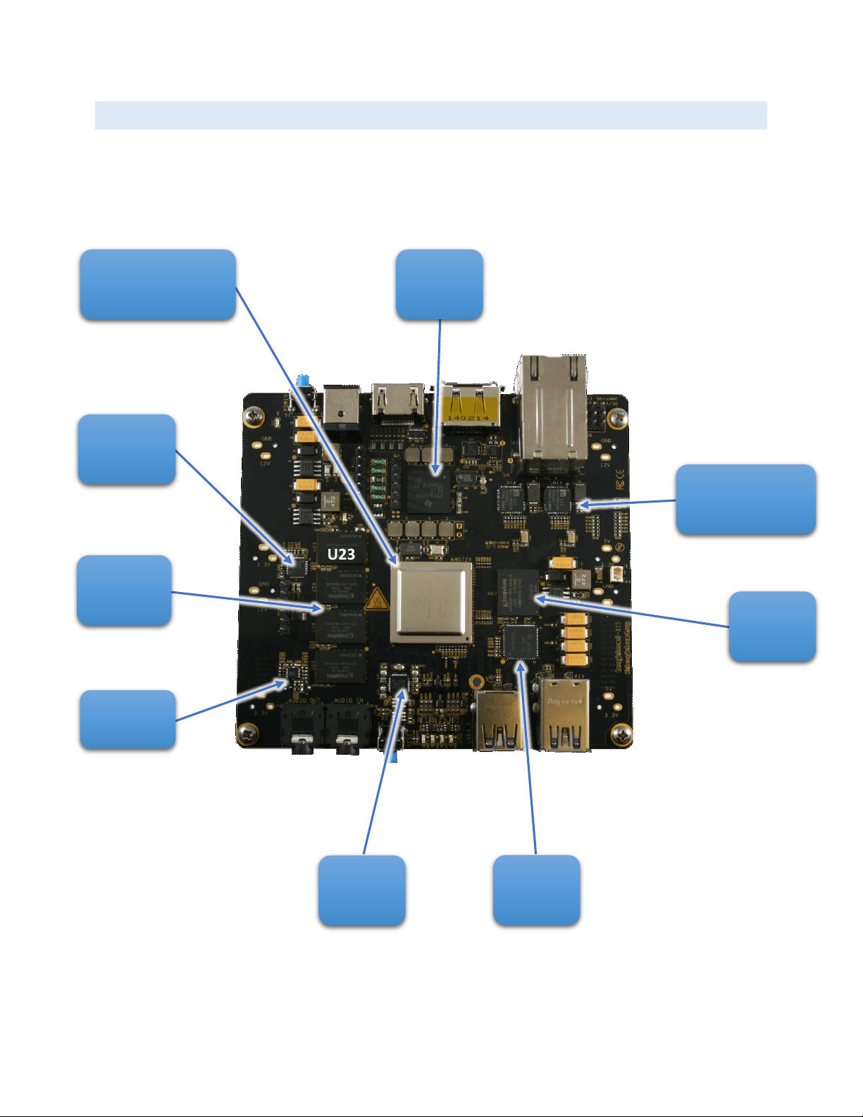
MAJOR COMPONENTS
Figure 7 shows the major IC and components on the EPD-X15.
Figure 7 - Locations of major ICs on the EPD-X15
U5
U11
U18
U23
U24
U26
U25
U14 U15
U22
U17
U
AM5728
PMIC
nFBGA
10/100/1000
ENET PHY x2
eMMC
4Gx8
USB
HUB
AUDIO
CODEC
DDR
Regulator
DDR3
4Gb x4
SERDES
CLK GEN
8
X15 QUICK START GUIDE
CHECK IT OUT
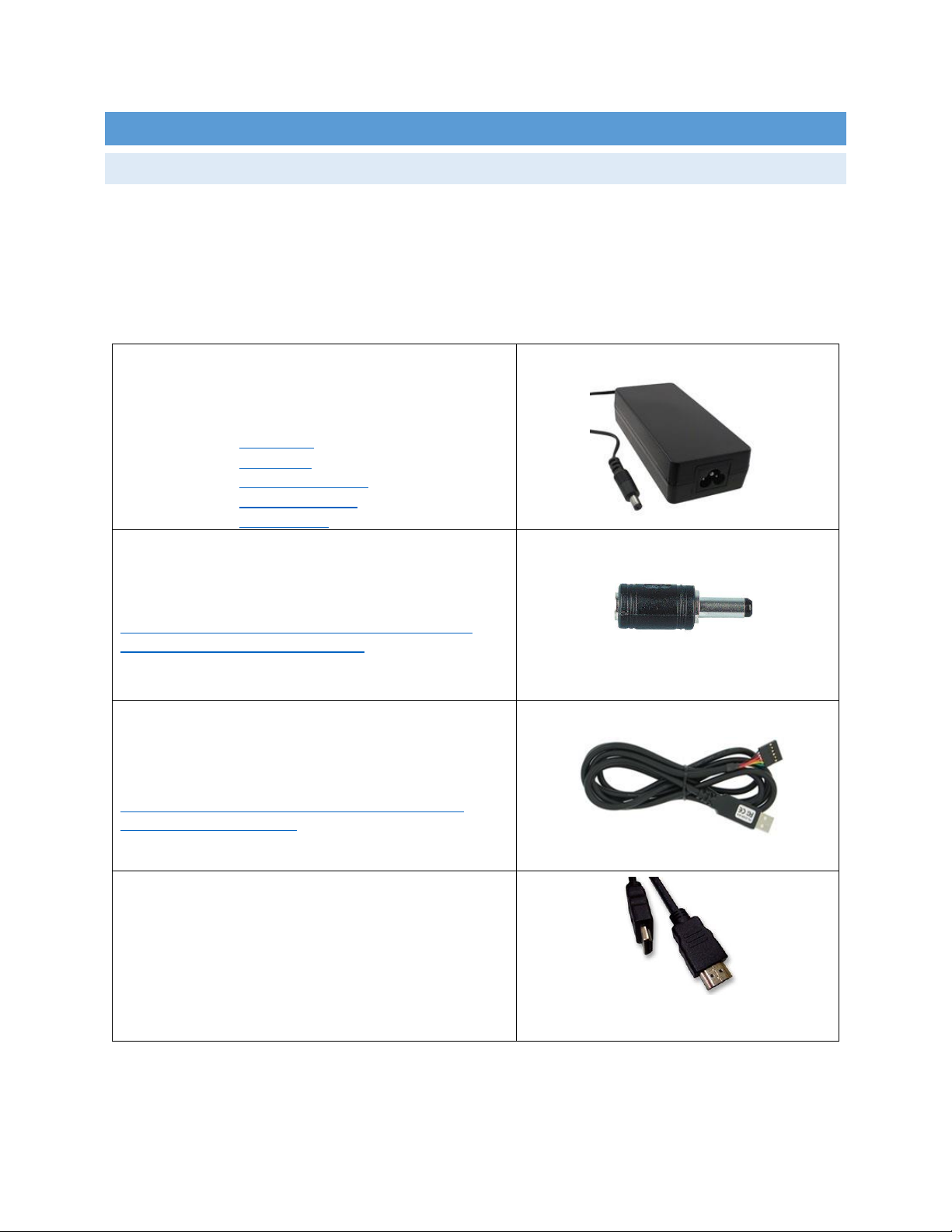
WHAT YOU WILL NEED
Table 1 shows the accessories needed to test all X15 peripherals. Some of these items may need to be purchased
if the user does not already own them. For power supply and serial cables please observe power requirements when
purchasing. The power jack on the EPD-X15 accepts a 2.5mm barrel to differentiate it from other board supplies.
Table 1 –LIST OF NEEDED ACCESSORIES
DC POWER SUPPLY
12V Supply
60W (5A min)
2.5mm x 5.5mm Barrel Plug Size
Option 1: TRG70A120
Option 2: VEF65US12
Option 3: CENB1060A1203F01
Option 4: TRG70A120-02E01
Option 5: PSAC60M-120 (needs adapter below)
2.5mm ADAPTER
Needed only for 12V supplies that have 2.1mm plug
Can be purchased online
One such source:
http://www.newark.com/multicomp/c4074/2-5mm-dc-
socket-to-2-1mm-dc-plug/dp/71T9782
TTL TO USB SERIAL CABLE
3.3V USB to SERIAL
Can be purchased from various sources
One such cable can be purchased here:
http://www.digikey.com/product-detail/en/TTL-232R-
3V3/768-1015-ND/1836393
HDMI AUDIO-VIDEO CABLE
Off the shelf quality Cable
HDMI-A Male to HDMI-A Male
Preferably 3ft or longer

9
X15 QUICK START GUIDE
ETHERNET CABLE
Two cables needed if both interfaces used
Use Cat5e cables
ENET PHYs have Auto MDI/MDI-x
Crossover or straight cables can be used
AUDIO CABLE
3.5mm jacks on both ends
Need two if Speakers do not come with one
SPEAKERS
Any desktop speaker system
With 3.5mm cable
HDMI MONITOR
HD monitor capable of 1080P
With integrated audio
Or Output jack for Audio
MICRO SD CARD
4GB to 16GB
Class 10
Standard Adapter
eSATA ADAPTER CABLE
eSATA to SATA cable
Combo cable
SATA DRIVE
SATA HDD - Hard Disk Drive
SATA SSD - Solid State Drive

10
X15 QUICK START GUIDE
USB THUMB DRIVE
USB3.0 thumb drive
Needed for file storage
Or to boot from USB3
WIRELESS KEYBOARD/MOUSE
Wireless combo will save USB ports used
Less wire clutter
Besides the accessories mentioned it is assumed the user has a PC or Laptop running Linux or Windows.
11
X15 QUICK START GUIDE
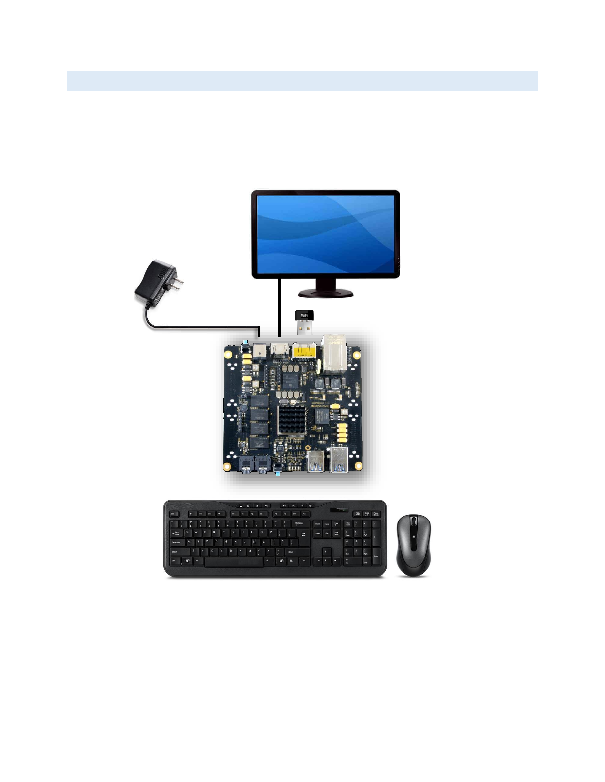
SETUP INSTRUCTIONS
Standalone w/Display and Keyboard/Mouse
In this configuration, the board works more like a PC, totally free from any connection to a PC as
shown in Figure 7. It allows you to create your code to make the board do whatever you need it to
do. It will however require certain common PC accessories. These accessories and instructions are
described in the following section
Figure 8 - Desktop Configuration
Additionally an Ethernet cable can be connected for network access.

12
X15 QUICK START GUIDE
PLUG IN YOUR CABLES
ETHERNET
There are two ports on the Ethernet connector on X15. Plug
cable into either port. Notice the orientation of cable
insertion between the two ports in Figure 8.
Figure 9 - ETHERNET PORTS
HDMI
Plug in HMDI cable into P11 HDMI connector on the top edge
of the X15 board.
Figure 10 –HDMI PORT
ESATA
Plug in eSATA cable as shown in Figure 10.
Figure 11 –eSATA PORT
13
X15 QUICK START GUIDE
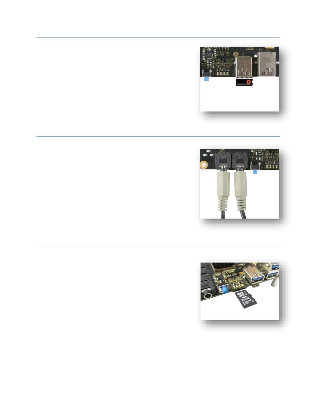
KEYBOARD AND MOUSE
To avoid using up multiple USB ports a Wireless keyboard and
mouse combination is preferred. The transceiver can be
installed in either USB port including P6 eSATA connector.
Figure 12 –Keyboard Transmitter
AUDIO
To playback and record audio, insert speaker cable into Audio
OUT jack of the X15 and an audio source into the Audio IN
jack.
Figure 13 –AUDIO JACKS
MICRO SD CARD
On the bottom edge of the X15 board, on the bottom side is
the micro SD card cage. I booting from SD card the micro SD
card is inserted as shown in Figure 12 with the top side facing
up. Change boot settings on J3-J4-J6 as shown in the next
section.
Figure 14 –micro SD CAGE
OUT IN

14
X15 QUICK START GUIDE
BOOT STRAPPING
J3, J4 and J6 can be strapped with Shunts for different booting options.
See Figure 15 for details.
Figure 15 –BOOT JUMPERS
SERIAL DEBUG
Plug in the USB to Serial cable into the 6 pin header P10.
Observe correct orientation. Pin1 is located at the top side of
the header.
PIN NUMBER
SIGNAL
1
Ground
4
Receive
5
Transmit
Figure 16 –SERIAL DEBUG PORT
TERMINAL SETUP
Plug the USB end into your PC or Laptop
and invoke MINICOM or TERATERM or your
favorite Terminal emulator program. The
settings for serial communications are:
Figure 17 –TERMINAL WINDOW
Pin1
Pin6
15
X15 QUICK START GUIDE
PLUG IN POWER
Once all the needed cables are inserted, plug in the DC power
adapter into the P1 jack. This is a 2.5mm center contact and
requires a supply that comes with a 2.5mm jack or an adapter
to 2.5mm. See Table 1 for more info.
Figure 18 –DC IN JACK P1
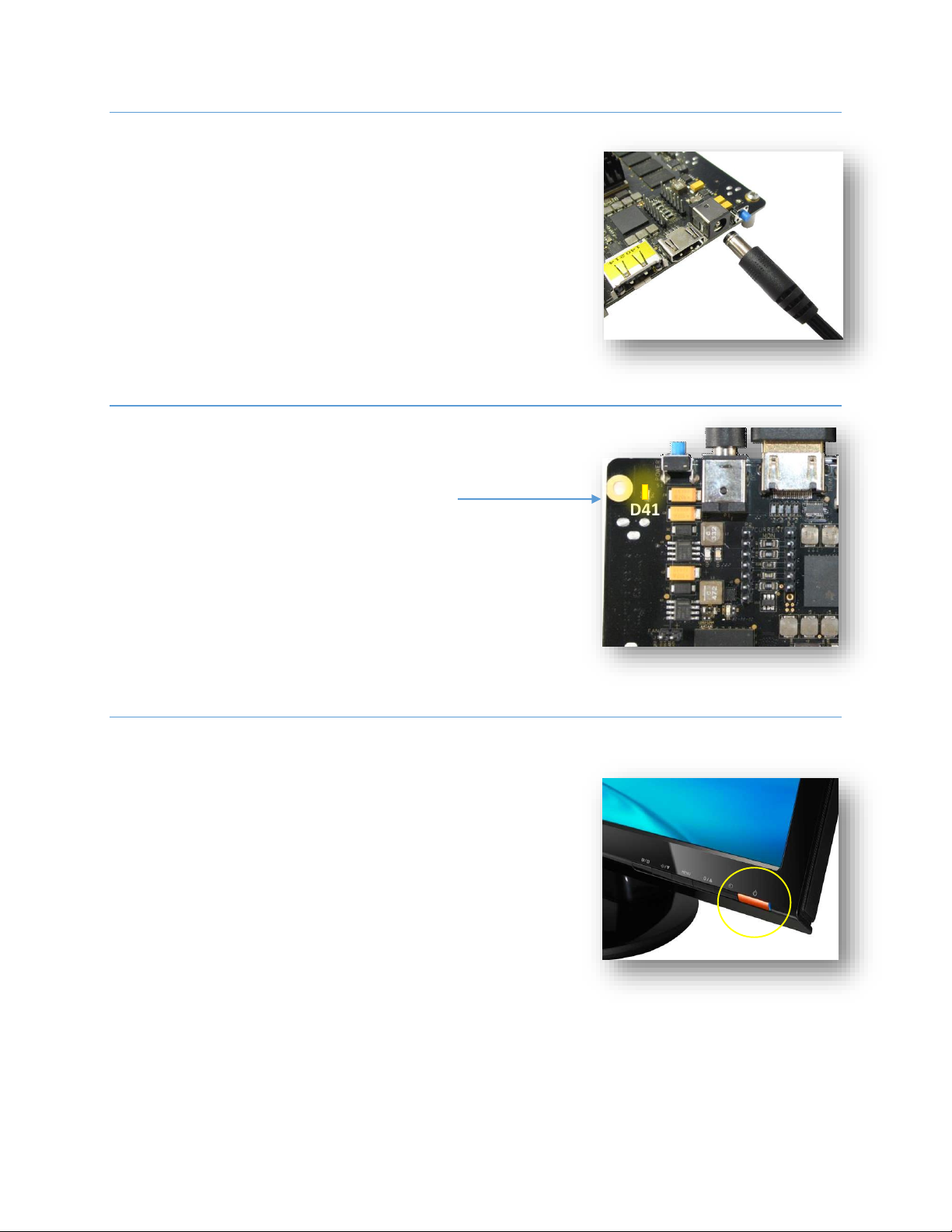
POWER LEDS
Once the power plug is inserted in P1, the Power LED D41 will
light up.
Figure 19 –DC 12V LED
TURN ON HD MONITOR
Once power is connected, turn on HDMI monitor. Change
input to the HDMI port the X15 is connected to.
Figure 20 –MONITOR POWER BUTTON
D41
D41 - 12V Present LED
16
X15 QUICK START GUIDE
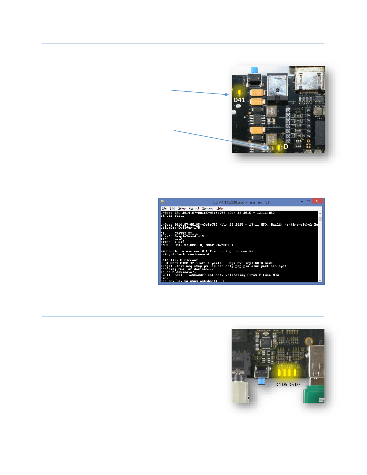
TURN ON X15 POWER
Though power is plugged in and the terminal is connected
there will be no activity observed on the terminal. LED D41
will glow.
To turn ON the X15 main power press the blue momentary
switch S1. This will cause LED D3 to glow showing that the
board power is ON.
Figure 21 –POWER LEDs
BOOTING
At this point the software present in eMMC
will start to boot and activity can be seen on
the terminal.
Figure 22 –POWER LEDs
USER LEDS
During the botting process the user may notice that the user
LEDs will blink.
Figure 23 –POWER LEDs
D41 - 12V Present LED
D3 - POWER ON LED
D4 D5 D6 D7
S1
D41
D3

17
X15 QUICK START GUIDE
Once the X15 interfaces are connected your system is ready to test. The next section will go through what you can
Figure 24 - Complete X15 system ready for test

18
X15 QUICK START GUIDE
TESTING
DEBUG:
The Serial debug port on the processor is UART3 via a single 1x6 pin header. In order to use the interface a USB to
TTL adapter will be required. The header is compatible with the one provided by FTDI and can be purchased from
various sources. Signals supported are TX and RX. None of the handshake signals are supported. On the PC you will
see activity that will take you to login prompt.
Figure 25 - Terminal activity on the Tera Term
A few seconds after the board power is turned on, the image in eMMC will boot and the Debian desktop will soon
show up on the HDMI monitor.
Figure 26 - Debian Desktop
19
X15 QUICK START GUIDE
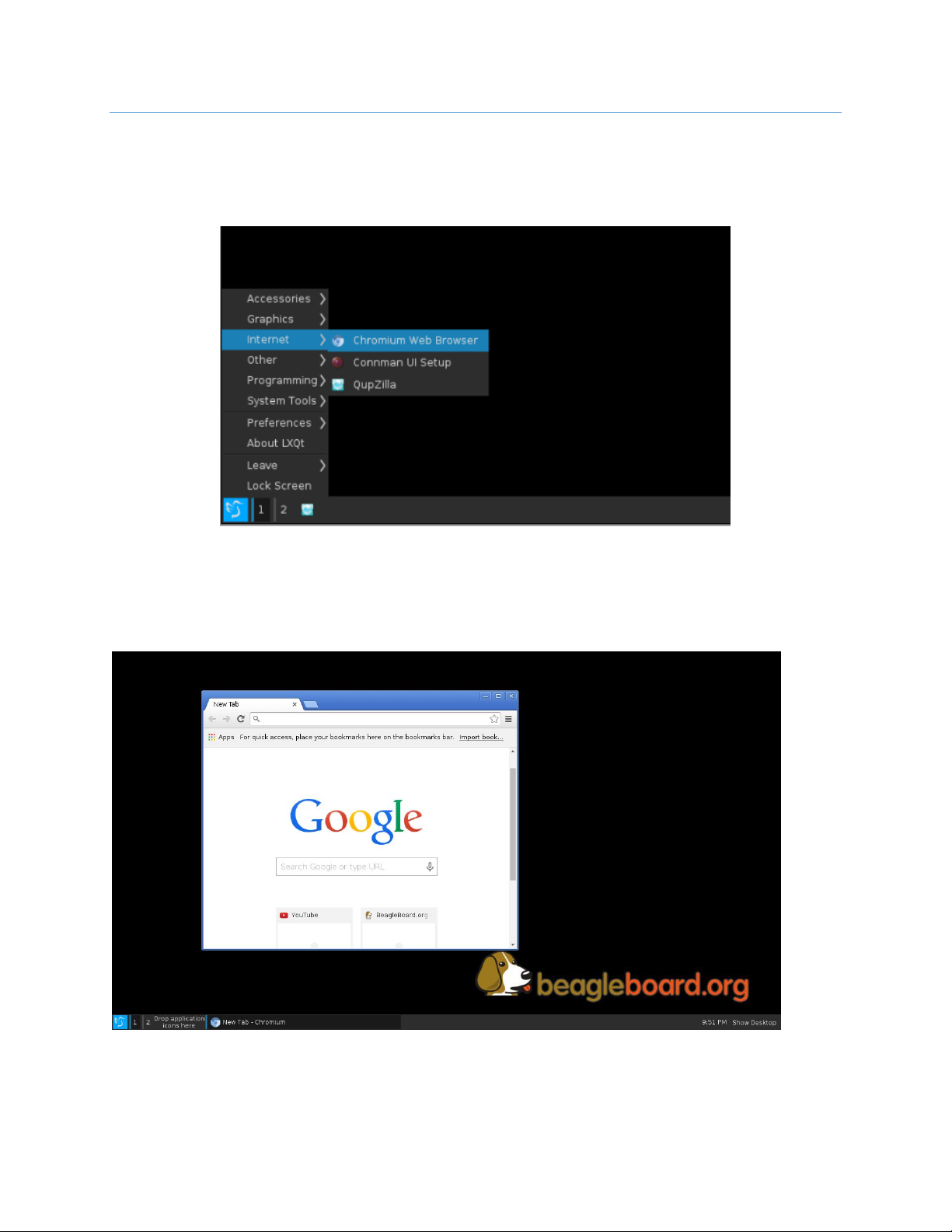
ETHERNET
Assuming the Ethernet cable is connected to one of the ENET ports on the EPD-X15 a quick test can be performed
by pointing the mouse to the bottom left corner of the Desktop and clicking the Debian menu logo. From here
point to Internet Chromium Browser.
Figure 27 - Open Web Browser
The browser window will open and if there is an internet connection, the browser will go to the homepage.
Figure 28 - Browser opens to the home page
The second Ethernet port can be similarly tested by moving the cable from ENET0 to ENET1. See Figure 3
Table of contents


 Series instruction manual")


