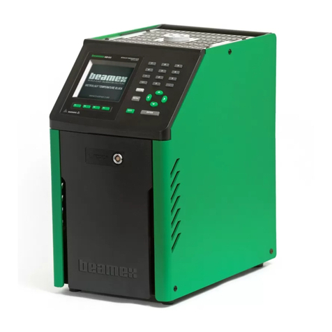
BEAMEX MC6-T User manual

MC6-T
Multifunction Temperature
Calibrator and Communicator
Applies to firmware version 4.00
Dear user,
We have made every effort to ensure the accuracy of the contents of this
manual. Should any errors be detected, we would greatly appreciate to
receive suggestions to improve the quality of the contents of this manual.
For more detailed technical data about Beamex MC6-T Multifunction
Temperature Calibrator and Communicator, please contact the
manufacturer.
© Beamex 2020
Beamex Oy Ab
Ristisuonraitti 10
FIN-68600 Pietarsaari
Finland
Tel:
E-mail:
Internet:
+358-10-5505000
https://www.beamex.com
8862000 / MC6-TuEng / Version 4.00


Table of Contents - iii
Table of Contents
Prologue....................................................................................7
About This Manual.............................................................................8
Where am I?.............................................................................8
Typographical Conventions.......................................................9
Unpacking and Inspection................................................................. 9
Feedback..........................................................................................10
MC6-T Safety.......................................................................... 11
Approvals......................................................................................... 11
Symbols Used..................................................................................11
Operating Environment....................................................................11
Safety Precautions and Warnings................................................... 13
Warnings Concerning Temperature.................................................14
Using the Temperature Block.................................................14
After using the Temperature Block.........................................15
Warnings Concerning Electrical Measurement and Generation..... 16
Warnings Concerning Pressure.......................................................16
General Warnings Concerning Pressure Measurement..........16
Warnings Concerning High Pressure......................................17
General description............................................................... 19
About MC6-T....................................................................................19
Hardware.................................................................................19
General...........................................................................19
MC6-T top view..............................................................21
Connectors on the Left Side of MC6-T..........................22
MC6-T Handle................................................................22
Memory.......................................................................... 23
Display............................................................................23
Batteries......................................................................... 23
Power Management................................................................24
User interface..........................................................................28
PC Communication/Calibration software................................ 32
USB Communication Driver...........................................32
MC6-T Related Tools Available for Personal
Computer................................................................... 32
Options.............................................................................................33
Software Options.....................................................................33
Hardware Modules/Options and Accessories.........................34
Accessory Holder Kit..................................................... 34
Related Products.....................................................................37

iv - Table of Contents
Active Terminals and Connections......................................39
General.............................................................................................39
Measurements..................................................................................40
Temperature Measurement (Thermocouple)..........................40
Temperature Measurement (RTD)..........................................41
Resistance Measurement....................................................... 42
Pressure Measurement...........................................................43
Connecting and Disconnecting External Pressure
Modules......................................................................43
Zeroing a Pressure Module........................................... 44
Current Measurement.............................................................44
Voltage Measurement.............................................................45
Frequency Measurement........................................................45
Pulse Counting........................................................................46
Switch Sensing....................................................................... 47
Generations/Simulations.................................................................. 47
Changing the Generated/Simulated Value............................. 47
Using the Soft Numeric Keypad.................................... 47
Spinning......................................................................... 48
Temperature Generation.........................................................49
Inserts to be used in the Temperature Block.................50
Thermocouple Simulation....................................................... 51
RTD Sensor Simulation..........................................................52
Current Generation (Source or Sink)......................................53
Voltage Generation.................................................................54
Resistance Simulation.............................................................54
Frequency Generation............................................................ 55
Pulse Generation.................................................................... 56
Thermocouple Connections.............................................................57
Tools........................................................................................59
Tools for Measurements..................................................................60
Additional Stability Check....................................................... 62
Tools for Generations/Simulations...................................................64
Temperature Calibrator......................................................... 67
About Temperature Calibrator......................................................... 67
The Menu................................................................................70
Calibrator................................................................................ 71
About Calibrator...............................................................................71
Documenting Calibrator........................................................73
General.............................................................................................73
Calibration Software................................................................74
Calibrating Instruments....................................................................74

Table of Contents - v
Generating/Simulating the Input Value...................................75
Instrument List........................................................................ 75
Instruments.....................................................................76
Instrument List Window Menu....................................... 87
Plant Structure Levels....................................................88
Work Order View Mode.................................................88
Instrument Overview Window.................................................90
Calibrating an Instrument Using MC6-T................................. 91
Changing the Pressure Module During Calibration........95
About Fieldbus and HART Device Specifics..................96
Calibration Results...........................................................................97
Deleting Calibration Results....................................................98
Get mapped value feature...............................................................98
Getting and Editing Mapped Data.......................................... 99
Preparations...................................................................99
Getting Default Mappings............................................ 100
Customizing the Mappings...........................................100
Mobile Security Plus software option.............................................103
General..................................................................................103
Applied Restrictions..................................................... 103
Data Logger..........................................................................105
General...........................................................................................105
Doing a Data Log.......................................................................... 106
Configuring............................................................................106
Saving and Opening Configurations............................109
Starting the Data Log............................................................110
Viewing and Saving or Deleting the Results.........................111
Viewing Saved Data Log Results.........................................112
Transferring Data Log Results to a Personal Computer....... 113
Communicator......................................................................115
General...........................................................................................115
Warnings............................................................................... 118
Connections................................................................................... 118
Selecting the Instrument................................................................120
List of Found Devices...........................................................121
About Instrument Parameters........................................................122
Instrument Parameters in General........................................122
Calibrating or Data Logging HART Instruments....................123
Calibrating or Data Logging Fieldbus Instruments................124
Editing Parameters................................................................125
Trimming a HART Instrument...............................................126
Trimming a Fieldbus Instrument...........................................129
HART Device Description Specifics...............................................131
About HART Device Description...........................................131
Basic View................................................................... 132
Managing Digital Communication Instrument Configurations........ 134
General..................................................................................134

vi - Table of Contents
Tools in MC6-T.....................................................................135
Saving Configurations..................................................135
Viewing/Managing Configurations................................135
Beamex MC6 Fieldbus Configuration Viewer.......................136
Uploading Configurations.............................................137
Linking Configurations to CMX.................................... 137
Settings................................................................................. 139
Settings overview...........................................................................139
Maintenance..........................................................................141
Replacing the mains fuses............................................................ 141
Overtemperature Protection Test Mode.........................................142
Cleaning instructions......................................................................143
Firmware Update............................................................................144
Recalibrating MC6-T......................................................................144
Disposal of Waste Electrical and Electronic Equipment................ 145
Beamex and WEEE..............................................................145
Service and transportation instructions............................147
Safe delivery for service................................................................147
Resetting MC6-T............................................................................149
Additional Information.........................................................151
User Defined Function Data..........................................................151
User Defined PRT/RTD Sensors..........................................152
General.........................................................................152
Callendar van Dusen Formula for PRTs......................154
ITS-90 PRT Sensor..................................................... 155
Factor........................................................................... 157
Check Sensor Conversion...........................................158
User Defined Transfer Functions..........................................159
User Defined Pressure Units................................................161
User Defined Steps Calibration Points................................. 163
Controller Communication.....................................................164
What Can be Done With Controller Communication....165
Configuring Controller Communication........................166
Changing Controller During Calibration....................... 167
Index.......................................................................................................169

- 7
Prologue
Thank you for buying Multifunction Temperature Calibrator and
Communicator.
Beamex MC6-T is an advanced, high-accuracy field calibrator and
communicator. It offers calibration capabilities for temperature, various
electrical signals as well as pressure. MC6-T also contains a fieldbus
communicator for HART, FOUNDATION Fieldbus and Profibus PA
instruments.
MC6-T consists of two main parts: Temperature Block and Process
Calibrator. MC6-T is equipped with an internal battery, therefore the
Process Calibrator functions can be used without mains voltage.
There are two different models available for MC6-T:
• MC6-T150 that can generate temperatures between -30..150 °C, at
ambient temperature of 23 °C.
• MC6-T660 that can generate temperatures between 50..660 °C.
This manual is valid for both models.
MC6-T's main features are multifunctionality and ease-of-use. MC6-T is
one device with five different operational modes: Temperature Calibrator,
Calibrator, Documenting Calibrator, Data Logger and Communicator.
In addition, MC6-T communicates with Beamex CMX and LOGiCAL
calibration softwares, enabling fully automated and paperless calibration
and documentation. MC6-T can also communicate with external
temperature and pressure controllers/generators.

8 - Prologue
About This Manual
MC6-T User Manual is divided into several parts as follows:
•Prologue, contains a general presentation of MC6-T.
•MC6-T Safety, includes safety warnings and precautions.
•General description discusses general matters.
•Active Terminals and Connections. Whatever you measure, generate
or simulate, here's how to make the necessary connections.
•Tools, presents the tools available in MC6-T.
•Temperature Calibrator, an operational mode for using the
Temperature Block to manually calibrate up to three temperature probes
or instruments simultaneously.
•Calibrator. A more generic operational mode which allows you to
measure/generate/simulate two things at the same time etc.
•Documenting Calibrator concentrates on instrument calibration using
the full featured documenting calibrator.
•Data Logger. Collecting and reviewing data and transferring logged
data to a PC.
•Communicator. Invoking digital communication with modern
instruments. This feature is optional.
•Settings. How to customize MC6-T and what the About window
contains.
•Maintenance. Contains a description of maintenance actions available
to the user.
•Service and transportation instructions. Useful information about
how to send the device for service.
•Additional Information. About advanced tools for, e.g. adding custom
pressure units, connecting external devices etc.
Where am I?
The header of each page in MC6-T User Manual informs you of where you
are: The even page shows the part you are in and the odd page shows the
main topic you are currently viewing.
Example of even page header:
2 – Part 1, Introduction
Example of odd page header:
About This Manual – 3

Unpacking and Inspection - 9
Typographical Conventions
The following typographical conventions apply to the MC6-T User Manual:
Bold text is used in following situations:
• References to User Manual topics and parts,
• MC6-T keywords, i.e. terms shown in the User Interface and
• other keywords, e.g. the names of fieldbus parameters.
Note: This is a note. Notes typically inform you of something
useful concerning the current topic.
CAUTION: This is a caution. Whenever you see a caution, read
it carefully and take it seriously. By not observing cautions, you
may damage the calibrator.
Warning: This is a warning. Whenever you see a warning, read
it carefully and take it seriously. By not observing warnings, you
may -at worst- damage the calibrator and/or even risk your life.
Unpacking and Inspection
At the factory each new MC6-T passes a careful inspection. It should
be free of scrapes and scratches and in proper operation order upon
receipt. The receiver should, however, inspect the unit for any damage
that may have occurred during transportation. If there are signs of obvious
mechanical damage, package contents are incomplete, or MC6-T does not
operate according to specifications, contact the purchasing sales office as
soon as possible.
If you have to return the device to the factory for any reason, use the
original packing whenever possible. Include a detailed description of
the reason for the return. Read also chapter Service and transportation
instructions, section Safe delivery for service.
For a description of available options, see Options.

10 - Prologue
Standard accessories:
• Accredited calibration certificate,
• this User Manual,
• Warranty Card,
• insert removal tool,
• Mains cord specific to your regions mains electricity,
• Cu/Cu extension cable,
• test leads,
• clips as follows:
◦ a pair of Grabber clips and
◦ two pairs of Alligator clips,
• USB cable,
• "Stay up to date" card, which contains links to Beamex website, where
different software tools (e.g. remote controller) can be downloaded
from,
Feedback
We want to improve our products and services constantly. Therefore we’d
like to know Your opinion of the product You use. Please spend a moment
of Your valuable time by giving us feedback about the product.
Beamex Oy Ab
Quality Feedback
Ristisuonraitti 10
FIN-68600 Pietarsaari
Address:
FINLAND
E-mail: [email protected]
Internet: https://www.beamex.com

Approvals - 11
MC6-T Safety
Approvals
IEC 61010-1:2010
IEC 61010-2-010:2014
Safety Directive 2014/35/EU
IEC 61010-2-030:2010
EMC Directive 2014/30/EU EN 61326-1:2013
Symbols Used
The following symbols concerning safety are used on the MC6-T.
Caution! See manual for further information
Caution! Hot surface
Operating Environment
Warning: Only use the calibrator for purposes and in
environments specified in the user manual.
• Do not use in wet conditions.
• Do not use in pollutive environments.
• Do not use in potentially explosive environments.

12 - MC6-T Safety
Operating
Temperature
0 … 45 °C (32 … 113 °F)
Storage Temperature -20 ... 60 °C (-4 ... 140 °F)
Operating Humidity 0 to 90 % R.H. non condensing
Storage Humidity 10 to 60 % R.H. non condensing
Max. safe operating
altitude
5000 m (approx. 16404 ft)
Pollution Degree 2 (only non-conductive POLLUTION occurs except
that occasionally a temporary conductivity caused
by condensation is expected)
Indoor use only
Note: Beamex provided temperature specifications are valid for
ambient temperatures between 13..33 °C. Outside of this scope,
temperature coefficients must be used. For more information
about temperature coefficients see User Guide for Beamex CMX
Calibration Software.
Note: MC6-T150's heating/cooling modules undergo normal
aging process during usage, after which minimum reachable
calibration temperature may be higher.
Note: Using the calibrator in a highly pollutive environment,
such as coal mine and steel factory is not allowed, unless
the calibrator is stored and used in a non-pollutive area, for
example a dedicated calibration room that has suitable air filters.
Contamination of conductive dust can cause electrical hazard.
Note: If the calibrator has been stored in different environment,
it should be allowed to stabilize to new environment before use.
For all measurement ports except IN and OUT a cable not
longer than 3 m must be used.
Sometimes it is necessary to use a portable radio transceiver
while working with the calibrator. To prevent calibration errors
caused by the radio frequency interference, keep the radio
far (at least 1 meter) from the calibrator and the circuit under
calibration while sending.

Safety Precautions and Warnings - 13
Safety Precautions and Warnings
CAUTION: Read and fully understand this manual and all
other safety instructions before operating this Multifunction
Temperature Calibrator and Communicator.
CAUTION: Only qualified and trained personnel is allowed to
use the MC6-T.
Working with MC6-T involves the usage of temperature,
electrical and pressure instruments. Only personnel with good
experience and knowledge of high temperature media, high
temperature instruments and connections are allowed to work
with the Temperature Block. Incorrect use may result in
damage to the device and/or personal injury.
Warning: Do not use MC6-T in any other way than as
described in thisUser Manual. If this equipment is used in
a manner not specified by the manufacturer, the protection
provided by it against hazards may be impaired.
Warning: To ensure safe use of the MC6-T follow these rules:
• Mains cord of correct type and rating must be used. The
Mains cord of the calibrator is equipped with a grounding plug
for your protection against electrical shock hazards. It must be
plugged directly into a properly grounded receptacle.
• Always make sure that mains inlet socket is easy to reach in
case the Mains cord needs to be unplugged. It is located at
the front of the device for maximizing safety.
• The device must always be used in upright standing position.
• Free space must be ensured around the calibrator. 25 cm is
required on all sides and 1 m above the calibrator to allow
correct ventilation.
Warning: Use MC6-T only if you are certain of that it can be
used safely. Safe use of MC6-T is no longer possible if one or
more of the following cases are true:
• When the enclosure of MC6-T is evidently damaged
• When MC6-T is not functioning as expected
• When there is unusual smell emitted by the battery of the
device
• After prolonged storage in unfavorable conditions
• After serious damage during transport

14 - MC6-T Safety
Warnings Concerning Temperature
Using the Temperature Block
Warning: The MC6-T is a temperature calibrator which
has been designed for calibrating instruments with typical
industrial calibration procedures. It has not been designed for
prolonged use at a temperature setpoint. Very low and very high
temperatures may cause injuries if touched. Temperatures below
dew point may cause condensation on cold surfaces in high
humidity environments. If water gathers on top of the device,
wipe the excess liquid away with a clean cloth. Do not leave the
calibrator unattended. Always power off the calibrator when not
using it.
Warning: The areas marked with hot surface warning symbol
might be hot during usage of the calibrator and must not be
touched. Never leave the calibrator unattended while it is hot.
The hot warning symbol next to the screen will light up to
indicate when the Temperature Block is hot.
Warning: A removable insert must not be removed from or
inserted to the Temperature Block when block temperature is
above 50 °C. Do not touch the insert when it is hot. Note that the
instruments to be calibrated may also be hot and must not be
touched during calibration.
Note: Use sensor heat shield when calibrating sensors at
temperatures above 150 °C to protect the handle and internal
structures of the sensor.
Warning: Any heat-transfer media, such as oil or paste, must
not be used with a dryblock calibrator. Make sure that the
Temperature Block boring is clean. If necessary, use a soft wipe
or compressed air to clean it.
Warning: Avoid handling flammable objects or liquids near the
calibrator as they might catch fire.

Warnings Concerning Temperature - 15
Warning: MC6-T's handle must be in down position during
calibration to prevent it from getting too hot.
After using the Temperature Block
Warning: If the Temperature Block has been heated up to
temperatures above 50 °C, it must be cooled down below this
temperature before switching off the device.
Warning: If the Temperature Block has been cooled down to
temperatures below dew point, it must be heated up until all
water has evaporated from the Temperature Block and insert.
Temperature Block must then be cooled down below 50 °C
before switching off the device.
Warning: Always remove the insert from the Temperature Block
when not using the calibrator. Use the insert removal tool for
removing the insert.
Warning: Always switch off the Mains switch when not using
the device.
Warning: Never set the device inside a carry case if the
Temperature Block temperature is above 50 °C or below dew
point.

16 - MC6-T Safety
Warnings Concerning Electrical
Measurement and Generation
Warning: MC6-T's OUT section terminals are protected against
over voltage and over current as far as it has been possible
without affecting the accuracy. Do not however connect signals
that are above the measurement range of the selected Function.
Maximum output voltage from MC6-T's terminals is below 30
V. If you, however, connect together voltages from the IN and
OUT sections or if you connect external voltages to MC6-T, the
resulting voltage may be high enough to be hazardous.
There is no galvanic isolation between the USB, Ethernet and
External Pressure Module connectors.
However there is a galvanic isolation between MC6-T's IN and
OUT sections. R3 connector is also galvanically isolated from
the other connectors. It is for functional purposes only. Do not
exceed 60 VDC / 30 VAC / 100 mA between any terminals.
Functional isolation is not intended for protection against
transient overvoltages. Do not connect measuring terminals to
circuits where transient overvoltages are possible.
Warnings Concerning Pressure
General Warnings Concerning Pressure
Measurement
Warning: The maximum pressures of optional pressure T-
hoses may not be exceeded.
Applying higher pressure than the maximum pressure can be
hazardous.
We recommend the use of the optional pressure hose sets.
When using other hoses and connectors, make sure they are
high quality products that withstand the used pressure.

Warnings Concerning Pressure - 17
Warning:
Always depressurize the system before opening or connecting
any pressure fittings or connectors. Use proper valves for
venting the system. Ensure that all connections are made
correctly and that the hose and the connectors are intact.
External pressure modules have the allowed media printed on
the module's sticker. Using unsuitable pressure media may
destroy the pressure module/calibrator.
Warning: External Pressure Modules: Use only the pressure
media stated on the pressure module. Use of wrong type of
Pressure Media may destroy the pressure module.
Never exceed the maximum pressure of a pressure module. The
maximum pressure of external modules is stated on module's
sticker and mentioned in the Instruction Booklet that is provided
with the external module.
Never plug a hose with your hands or put hands in front of a
gas spray coming from a leakage. A gas bubble in the blood
circulation can cause death.
Warnings Concerning High Pressure
Warning: High pressure is always dangerous. Only personnel
with good experience and knowledge of high pressure liquid, air
and nitrogen operations are allowed to work with the module.
Read carefully all these instructions and familiarize yourself
with local safety instructions for high pressure operations before
starting the use.
When using gas, the system must not contain any liquid,
especially if you do not know how they may react under
pressure. Use of clean air or nitrogen is recommended as
gaseous pressure media. Liquid pressure media should be
preferred when using modules with a pressure range of 60 bar
(30000 psi) or more.

18 - MC6-T Safety
Warning: If you use nitrogen, minimize the leak to the
atmosphere and take care of sufficient ventilation. Close the
valve of the nitrogen cylinder, when the system is not in use.
Increase in the percentage of nitrogen in the ambient air may
cause unconsciousness and death without warning. Read
carefully the safety instructions for nitrogen and make sure that
other people in the same space are aware of the danger.
Use of liquid pressure medium is recommended with pressure
measurement modules at higher pressure range. Use water
or suitable hydraulic oil. Check that the used liquid is not
aggressive against the materials used in the transducer or
tubing. When using liquid, minimize the amount of air in the
system to minimize the amount of spilled liquid in case of
leakage.
Warning: Do not use the same tubing with different liquids or
gases.
Check what the local regulations say about construction and
use of pressurized vessels. The regulations normally control
construction and use of systems where the product of the
pressure and volume exceeds a certain limit. The volume of this
system depends on the instrument connected to it.
High pressure gas is dangerous because it can break the
container and the flying splinters may cause injury. Also small
leaks of gas may be dangerous because the high velocity of the
leaking gas jet enables penetration through skin. If a gas bubble
gets into the blood circulation, it can cause death. The leak jet is
particularly penetrative, if some liquid is coming with the gas.

About MC6-T - 19
General description
Things discussed in this part:
• Briefly about MC6-T's hardware and firmware
• Available software and hardware options
• Power management explanation
About MC6-T
Hardware
General
Figure 1: MC6-T, overview presents a general view of the MC6-T, its parts
and its buttons' functionality.
Figure 1: MC6-T, overview

20 - General description
Legend:
1. Temperature Block. See also Figure 3: MC6-T, top view.
2. Display and Touch Panel.
3. Home button. Press this button to return to Home View.
4. Hot Temperature warning symbol that lights up when the
Temperature Block is hot.
5. Process Calibrator Power button, see chapter Power Management.
6. Arrow buttons. First press displays the Hardware Focus Indicator.
Further presses move the indicator on the Display.
7. Enter button for selecting the item surrounded with the Hardware
Focus Indicator.
8. RTD and Resistor connector (R2).
9. RTD and Resistor connector (R3).
10. Voltage, Frequency and Switch input (IN).
11. Current Measurement, Loop Supply, HART® and Fieldbus
connection (IN).
12. Voltage, Current and Frequency output (OUT).
13. RTD and Resistor connector (R1).
14. Thermocouple connectors (TC1 and TC2). TC1 for cables and
standard TC plugs and TC2 for TC plugs with flat contacts.
15. Mains switch (115 V / 230 V). For more details see Power
Management.
16. Mains Inlet socket (115 V / 230 V) to connect the Mains cord.
17. Fuse holders.
18. External Pressure Module connector.
19. Internal Barometric Pressure Module (optional).
20. Ethernet connector.
21. USB-B connector.
22. USB-A connector.
Table of contents
Other BEAMEX Measuring Instrument manuals
Popular Measuring Instrument manuals by other brands
HBM
HBM C16i series Mounting instructions
Keysight Technologies
Keysight Technologies N9030A Installation note

Hanna Instruments
Hanna Instruments HI 83748 instruction manual

Truvelo
Truvelo ProLaser 4 Operator's manual
Siemens
Siemens Clinitek Advantus Operator's guide
ProMinent
ProMinent DULCO flex Control operating instructions
AEMC instruments
AEMC instruments DIGITAL FLEXPROBE 400D-6 user manual
GE
GE DINAMAP ProCare Service manual
Extech Instruments
Extech Instruments 380460 user guide

Prosense
Prosense FMM50-1001 operating instructions
Fluidwell
Fluidwell E115-P user manual
Agilent Technologies
Agilent Technologies FieldFox N9923A user guide
