Nitto TGF450 Series User manual

User’s Manual Rev1.0
Date:15/07/2015 User’s Manual
1/47
TGF450 Series
Thermal Mass Flowmeter
User’s Manual
Nitto Instruments Co.,Ltd Japan
Hefei Comate Intelligent Sensor Technology Co,. Ltd

User’s Manual Rev1.0
Date:15/07/2015 User’s Manual
2/47
Dear Customer:
Thanks for choosing our flowmeter products. Please read this manual carefully to know how to
install and use this product to ensure its best performance. If you should encounter a problem when
using the product, please do not hesitate to let us know. We are going to take no responsibility if the
flowmeter is damaged because of anyone repair or replace any parts of it with our permission.
Support
Please reach to us according to the contact information below to get support or update of our VFM60
vortex flowmeter:
zWebsite
http://www.comatemeter.com
zTelphone:
+86-0551-63653542
zE-mail:
supports@ comatemeter.com
Place an order
If you need to place an order or need to know the status of your processing orders, please contact us
according to below information:
Phone: +86-0551-63653542
Website: www.comatemeter.com
Email: sales@comatemter.com
Address:2nd floor, Building D2, Hefei Innovation Industrial Park,No.800 Wangjiang West Road,Hefei
Tech Development Zone, Hefei, China
Postal code:230088

User’s Manual Rev1.0
Date:15/07/2015 User’s Manual
3/47
TABLEOFCONTENTS
SUPPORT.........................................................................................................................................2
PLACEANORDER............................................................................................................................2
1GENERAL......................................................................................................................................6
1.1MODELNUMBERANDGENERALSPECIFICATION.........................................................................6
1.2PACKINGLIST.............................................................................................................................6
1.3STORAGE...................................................................................................................................6
1.4MEASURINGPRINCIPLE..............................................................................................................6
2INSTALL........................................................................................................................................7
2.1FINDMOSTSUITABLELOCATION................................................................................................7
2.2REQUIREMENTONSTRAIGHTPIPELINE.....................................................................................8
2.3REQUIREMENTONINSERTIONDIRECTION.................................................................................9
2.4PROCEDUREOFINSTALLATION.................................................................................................10
9)INSERTTHEMETERTOTHEDEPTHSASCALCULATEDWITHTHEHOTTAPMOUNTINGTOOL.
(PLEASEREFERENCETOTHEMANUALOFHOTTAPMOUNTINGFORDETAILS).NOWHOLDTHE
SLEEVE(PARTNO.3)WITHAWRENCHANDTIGHENTHENUT(PARTNO.4)WITHANOTHERWRENCH.
MAKESURETHENUTSLEEVEISHOLDINGTHEMETERTIGHTENLY..................................................13
3WIRING......................................................................................................................................13
3.1WIRINGFORTERMINALBOARD...............................................................................................14
3.2SHELLGROUNDINGANDELIMINATIONOFINTERFERENCE........................................................15
3.4REQUIREMENTONWIRING......................................................................................................15
4DISPLAY......................................................................................................................................16
4.1INTRUCTIONOFMULTI‐FUNCTIONALLCDDISPLAY...................................................................16
4.2UNITOFTHEVARIABLEDISPLAYED...........................................................................................17
4.3THREEBUTTONSETTING..........................................................................................................18
4.4TOTALFLOWDISPLAYING.........................................................................................................18
4.5STATUS....................................................................................................................................19
5SETTING.....................................................................................................................................19
5.1HOWTOSET............................................................................................................................19
5.1.1CODESETTING......................................................................................................................19
5.1.2DIGITALSETTING...................................................................................................................20

User’s Manual Rev1.0
Date:15/07/2015 User’s Manual
4/47
5.2SETTINGLIST............................................................................................................................22
CHART5.1CODESETTINGADDRESS...............................................................................................22
CHART5.2DIGITSSETTINGADDRESS..............................................................................................25
5.3EXAMPLEOFSETTING..............................................................................................................26
5.4PASSWORDSETTINGINSTRUCTION..........................................................................................26
6INSTRUCTIONOFRS485MODBUSCOMMUNICATION.................................................................27
6.1INTERFACEREGULATION..........................................................................................................27
6.2COMMENDS............................................................................................................................29
6.3CALCULATIONOFCRCPARITYCODE.........................................................................................31
6.4THEFLOATDATEFORMATOFTHEINSTRUMENT.......................................................................31
6.5THESEQUENCEOFTHEFLOATDATEBYTESOFINSTRUMENT.....................................................32
6.6MODBUSERRORREPONSE.......................................................................................................32
6.7EXAMPLESOFCOMMUNICATION.............................................................................................33
7INTRODUCTIONOFHARTCOMMUNICATIONPROTOCOL.............................................................33
7.1HARTCOMMANDS...................................................................................................................33
7.1.1COMMAND0:READTRANSMITTERUNIQUEIDENTIFIER........................................................34
7.1.2COMMAND1:READPRIMARYVARIABLEVALUE(PV).............................................................34
7.1.3COMMAND2:READPRIMARYVARIABLE’SCURRENTANDPERCENTAGEVALUE......................34
7.1.4COMMAND3:READPRIMARYVARIABLECURRENTANDDYNAMICVARIABLES......................35
7.1.5COMMAND6:WRITEPOLLINGADDRESS...............................................................................35
7.1.6COMMAND11:READUNIQUEIDENTIFIERASSOCIATEDWITHTAG.........................................36
7.1.7COMMAND12:READMESSAGE.............................................................................................36
7.1.8COMMAND13:READTAG,DESCRIPTOR,DATE......................................................................36
7.1.9COMMAND14:READPRIMARYVARIABLESENSORINFORMATION:DEVICESERIALNUMBER
ANDLIMITS...................................................................................................................................37
7.1.10COMMAND15:READPRIMARYVARIABLEOUTPUTINFORMATION......................................37
7.1.11COMMAND16:READFINALASSEMBLYNUMBER.................................................................37
7.1.12COMMAND17:WRITEMESSAGE.........................................................................................38
7.1.13COMMAND18:WRITETAG,DESCRIPTOR,DATE...................................................................38
7.1.14COMMAND19:WRITEFINALASSEMBLYNUMBER...............................................................38
7.1.15COMMAND34:WRITEPRIMARYVARIABLEDAMPINGVALUE..............................................39

User’s Manual Rev1.0
Date:15/07/2015 User’s Manual
5/47
7.1.16COMMAND35:WRITEPRIMARYVARIABLERANGEVALUES.................................................39
7.1.17COMMAND36:WRITEPRIMARYVARIABLEUPPERLIMITVALUE..........................................39
7.1.18COMMAND37:WRITEPRIMARYVARIABLELOWERLIMITVALUE.........................................40
7.1.19COMMAND40:ENTER/EXITPRIMARYVARIABLECURRENTMODE.......................................40
7.1.20COMMAND45:TRIMPRIMARYVARIABLECURRENTDACZERO............................................40
7.1.21COMMAND46:TRIMPRIMARYVARIABLECURRENTDACGAIN............................................41
8MAINTAINING.............................................................................................................................41
8.1HOWTOCHANGETHETRANSMITTER’SDIRECTION..................................................................41
8.2REPLACEATRANSMITTERCIRCUITBOARDS.............................................................................42
8.3REMOVETHEFLOWMETER......................................................................................................42
8.4HOWTOCLEANTHESENSORS..................................................................................................43
9TROUBLESHOOTINGANDREPAIR................................................................................................43
9.1SAFTYINTRODUCTION.............................................................................................................43
9.2TROUBLESHOOTINGANDREPAIR.............................................................................................43
9.3SELF‐DIAGNOSEFUNCTION......................................................................................................45
10REMARK...................................................................................................................................45
APPENDIX.....................................................................................................................................46

User’s Manual Rev1.0
Date:15/07/2015 User’s Manual
6/47
1 General
Every TGF450 thermal mass flowmeter will be carefully inspected before delivered to users.
Please carefully check if there is any damage on the package and product when you received them
Please check if the package contains all the accessories according to 1.2 or your purchase order.
Please make sure the person in charge of this device has carefully read this manual and understand its
descriptions.
1.1 Model Number and General Specification
Please check if the model number and specifications on the name plate match your requirement on the
purchase order.
Please kindly record the model number and instrument ID code, which will be required if you need and
service or support from us.
1.2 Packing List
When you recived the package, please check if it contains the items as below:
TGF450 thermal mass flowmeter x1
User’s manual x1
Calibration certificate x1
Quality certificate x1
Cable (For remote type only, length according to customer’s requirement)
Counter flanges (For wafer type, or for flanged type when customer requied so)
Screws and bolt (For wafer type, or for flanged type when customer requied so)
1.3 Storage
If the product needs to be stored for a long period before use, please be awared of below:
(1) The product should be kept in the origin package and same as it was when received.
(2) Please store the product in a proper location according to the requirements below:
Not in a uncovered field.
Not in a location where could have great vibration.
Please keep the enclosure of the meter closed.
The ambient temperature, atmospheric pressure and humidity should be:
Temperature: -20~+60℃;RH:5%~99% ;Pressure:86~106Kpa
1.4 Measuring principle
TGF450 Series Thermal Mass Flowmeter measures gas mass flow base on thermal diffusion theory and thermal
principle of Newton , It have two RTD sensor (ref to picture 1.2) located in the flow. One RTD is heated to T1 by a
heating power rate of P, the other is not heated but to measure the medium temperature T2. So there is a
temperature difference TD=T1-T2 . TD reach max when mass flow is 0. When the mass flow Q increases, the heat
on T1 is taken away so the T1 decline and the TD become smaller. So there is a certain relationship between
heating power rate P, difference of temperature TD and mass flow Q as below:
P/ T
D = K1 + K2 F(Q)K3

User’s Manual Rev1.0
Date:15/07/2015 User’s Manual
7/47
Picture 1.2 Principle
The K1,K2 and K3 in above equation is constant related to the character of medium . So the mass flow Q can be
get through measuring the heating power rate P and difference of temperature TD . In actual application, there are
two different method, one is consistent current method (keep the P unchanged) and the other is consistent
temperature method (keep TD unchanged)
2 Install
2.1 Find Most Suitable Location
2.1.1 Ambient temperature
Please avoid installing the flowmeter at a location where temperature could dramaticly changes. If the
meter is under heavy heat radiation, please implement effective heat insulation and venting method.
2.1.2 Atomosphere
Please do not install the meter at a locaition where the atomosphere contains a high level of corrosive
substance. If can not install the meter at a better location, please make sure there is enough venting.
2.1.3 Vibration
The meter should not be installed at a location where could have strong vibration. If the mounting
pipeline could have heavy vibration, the pipe line should be holden steady by some supporting racks.
2.1.4 Caution
(a) All screws and bolts should be tighen.
(b) Make sure there is not leakage point on the connection.
(c) The process pressure should not be higher than the meter’s rated pressure.
(d) Once the meter is under pressure, please do not screw the bolts and screws.
(e) When measuring harzad gas, do not breath the gas in
(f) If the meter is insertion mounted, please the outer of the connection part should be sealed with
proper sealant.
(g) If the meter is insertion mounted,

User’s Manual Rev1.0
Date:15/07/2015 User’s Manual
8/47
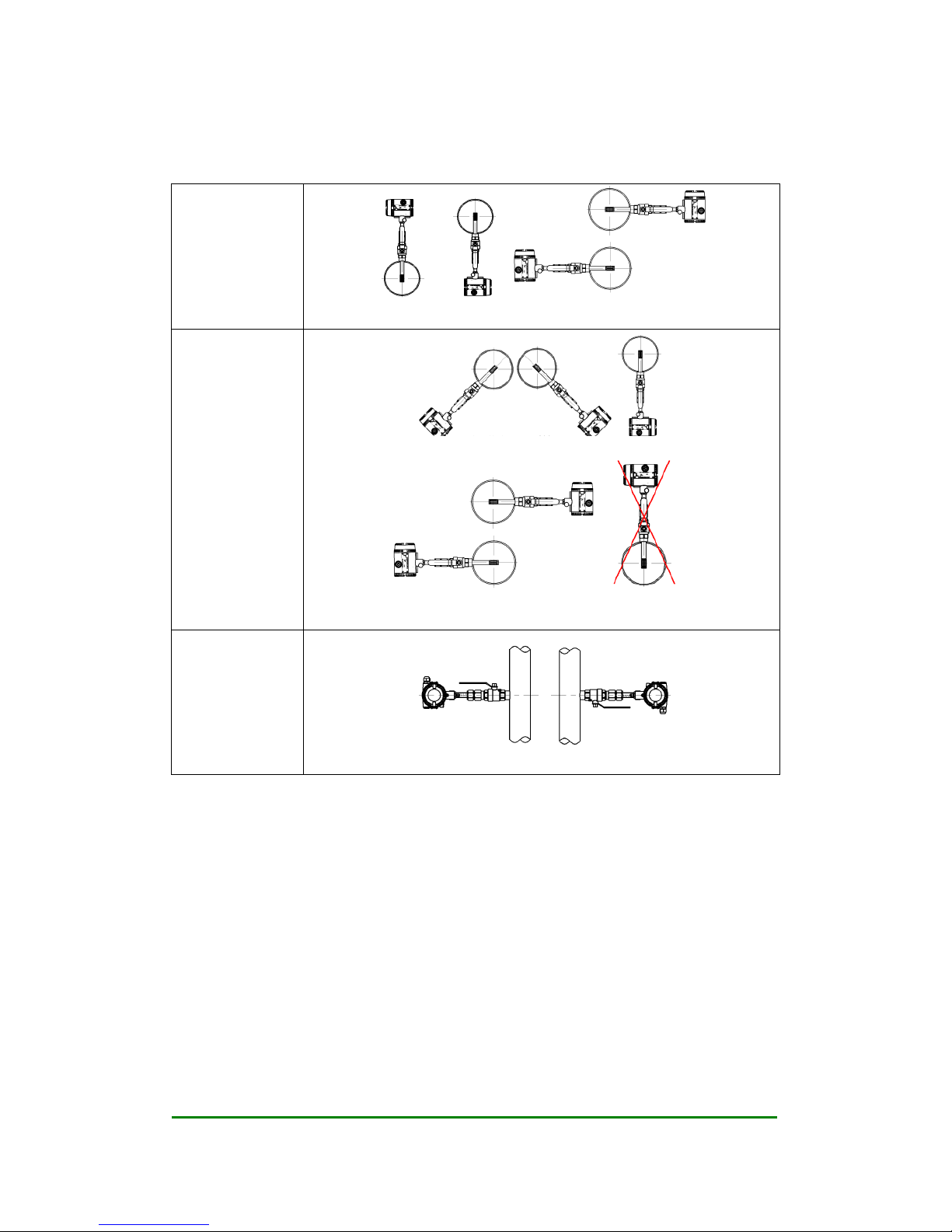
2.2 Requirement on straight pipe line
Standard
Curved pipe line in the
upstream or downstream
Curved pipe line that may creat
turbulence in the upstream or
downstream
There are valves or pressure
controller or any other device
may cause turbulence in
upstream or down stream of the
flowmeter
If the pipeline of the flowmeter
is upsized
If the pipeline of the flowmeter
is downsized
User’s Manual Rev1.0
Date:15/07/2015 User’s Manual
9/47
2.3 Requirement on insertion direction
On a horizontal
pipe line, normal
air or gas
Above or under the pipeline Side of the pipe line
On a horizontal
pipe line, high
humidity air or wet
natural gas.
45 degree under the pipe line or just under the pipelien
On the side of the pipe. Do not recommend to install the meter above the
pipeline
On a vertical
pipeline, when the
density of the gas is
higher than air

User’s Manual Rev1.0
Date:15/07/2015 User’s Manual
10/47
2.4 Procedure of installation
2.4.1 Nut sleeve insertion (No flow in pipeline)
1) Drill a hole on the position where the meter will be installed, Ø 13mm (± 0.5 mm)
2) Clean the burrs and sharps on where will be welded
3) Weld the MNPT 1/2” socket (Part No.1) on the open hole vertically. The socket and the open hole
should be concentric, and vertical to the center line of the pipe line
4) Connect the 1/2” ball valve (Part No.2) with FNPT threads on both ends to the socket. Seal the
thread connection with thread sealant. Please note the lever on the ball valve should be point to up
when the valve is open
5) Insert the flowmeter into the ball valve and the socket, connect the sleeve (Part No.3) on the meter
and the ball valve, seal the thread conection part with thread sealant. Tighten the nut (Part No.4) with
hand.
6) Calculate the insertion depth. The sensor should be in the middle of the pipe area, insertion
depth S=A/2+B+C. Please reference to the picture below
A: Inner diameter of the pipeline
B: Thickness of the pipe line
C: The distance between the top of the pipeline and the upper end of the nut when the nut is fixed

User’s Manual Rev1.0
Date:15/07/2015 User’s Manual
11/47
7) Adjust the direction of the flowmeter: Make sure the derection mark on the probe (Part No.5) is
pointing to the direction as the flow goes. Please reference to the picture below.
8) Insert the flowmeter to the depth S as calculated previous, now hold the sleeve (Part No.3) with
a wrench and tighen the nut (Part No.4) with another wrench. Make sure the nut sleeve is holding
the meter tightenly.
Remark: If flow rate higher than 90Nm/s or pipe size larger than DN400, will require 19mm
diameter probe, mounted in 1” ball valve and 1” socket and 22mm hole
2.4.2 Nut sleeve insertion (flow and pressure in pipeline)
1) Weld the MNPT 1/2” socket (Part No.1) on the pipeline vertically. The socket should be vertical to
the center line of the pipe line

User’s Manual Rev1.0
Date:15/07/2015 User’s Manual
12/47
2) Connect the 1/2” ball valve (Part No.2) with FNPT threads on both ends to the socket. Seal the
thread connection with thread sealant. Please note the lever on the ball valve should be point to up
when the valve is open.
3) Drill a hole with the hot tap hole opener, Ø 13mm (± 0.5 mm). (Please reference to the manual of
hot tap mounting for details)
4) Make sure the senor of the meter is with in the sleeve on the flowmeter, so the sleeve can protect the
sensor.
5) Connect the sleeve with the ball valve with the thread, please seal the 1/2” NPT thread connection
with thread sealant, (the ball valve should be closed)
6) Calculate the insertion depth. The sensor should be in the middle of the pipe area, insertion
depth S=A/2+B+C. Please reference to the picture below
A: Inner diameter of the pipeline
B: Thickness of the pipe line
C: The distance between the top of the pipeline and the upper end of the nut when the nut is fixed

User’s Manual Rev1.0
Date:15/07/2015 User’s Manual
13/47
7) Adjust the direction of the flowmeter: Make sure the derection mark on the probe (Part No.5) is
pointing to the direction as the flow goes. Please reference to the picture below.
8) Open the ball valve, please make sure that procedure 1~7 is operated properly before opening the
ball valve. The sleeve should be connected to the ball valve tightenly that the meter can not be ejected
out.
9) Insert the meter to the depth S as calculated with the hot tap mounting tool. (Please reference to the
manual of hot tap mounting for details). Now hold the sleeve (Part No.3) with a wrench and tighen
the nut (Part No.4) with another wrench. Make sure the nut sleeve is holding the meter tightenly.
Remark: If flow rate higher than 90Nm/s or pipe size larger than DN400, will require 19mm
diameter probe, mounted in 1” ball valve and 1” socket and 22mm hole
3 Wiring
The terminal board of TGF450 is as picture 3.1 below
Picture 3.1 TGF450 terminal board
On above board, V+ and V- are for power, the DC power should be within 15VDC~32VDC.
is pulse output terminal. A, B are “+” and “-” for RS485Modbus communication, I+ and I- are +
and – for 3-wire or 4-wire 4~20 mA. P+,P- are for pressure transmitter .
User’s Manual Rev1.0
Date:15/07/2015 User’s Manual
14/47
3.1 Wiring for terminal board
3.1.1 Wiringfor 3-wire pulse output
TGF450 use a current pulse output with 50% duty ratio. If the pulse reciving instrument require
voltate pulse, please add a resistor between “ ” and “V-”, the resistance should be within
500ohms~1000ohms, and power consumption should be no less than 0.5W.
Picture 3.2 Wiring of TGF450 3-wire pulse output
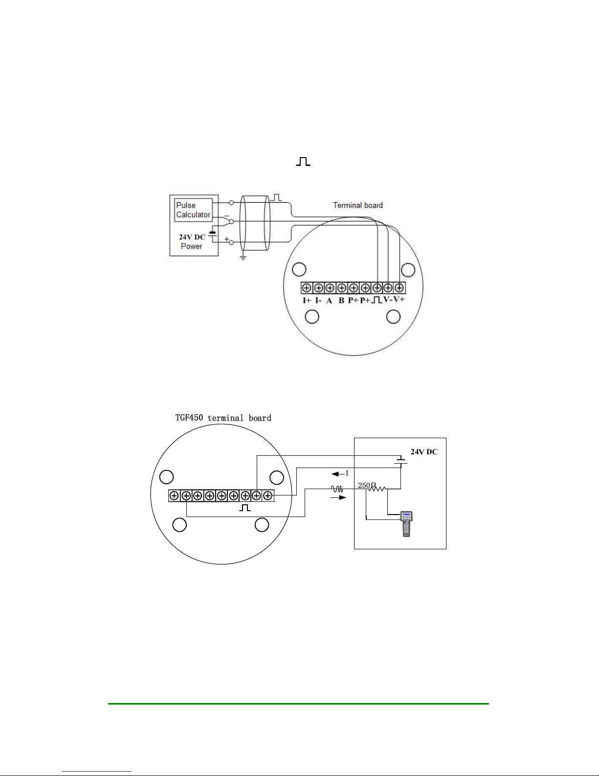
3.1.2 Wiringfor 3-wire HART@4~20mA
V-
BAI+ I- P+ P+ V+
Picture 3.3 Wiring of TGF450 3-wire HART@4~20mA

User’s Manual Rev1.0
Date:15/07/2015 User’s Manual
15/47
3.1.3 Wiringfor 3-wire HART@4~20mA
V-
BAI+ I- P+ P+ V+
24V DC
Picture 3.4 Wiring of TGF450 4-wire HART@4~20mA
3.1.4 Wiring for RS485
V-
BAI+ I- P+ P+ V+
Picture 3.5 Wiring of TGF450 RS485
3.2 Shell grounding and elimination of interference
In TGF450 thermal mass flowmeter the power supply of signal processing circuit is transferred from
outside power supply by a isolation type DC-DC transmitter with advanced grounding technology . The
field frequency interference can be isolated well.
When using this product , the “V-” of power supplier should not be connected with the ground .When
this product is used in a environment with strong interference , the shell should be clean connected with
earth through cable , so the interference can be eliminated .
3.4 Requirement on wiring
1) Please do not conduct wiring when the power is on in a explosive environment.
2) Please open the rear cover first, then inert the cable into back zone of housing thourgh the
water-proof cable gland.

User’s Manual Rev1.0
Date:15/07/2015 User’s Manual
16/47
3) Conduct wiring according to 3.2.
4) If possible, please conduct the wiring according to picture 3.6 to avoid the water get into the housing
through the cable.
Picture 3.6 Wiring instruction
4 Display
TGF450 thermal mass flow meter provide with local display and setting. Users can display several
variables on the local multi-funcational LCD display. The transmitter also has 3 buttons so users can do
setting on it.
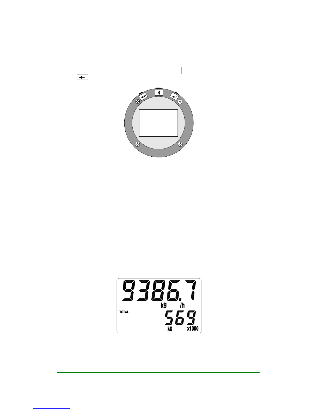
4.1 Intruction of multi-functional LCD display
TGF450 thermal mass flow meter has a display to indicate “Temperature” “Flow rate” “Total flow”
and more parameters. Please reference to picture 4.1 below.
Pitcure 4.1 TGF450 display

User’s Manual Rev1.0
Date:15/07/2015 User’s Manual
17/47
The LCD display has 2 areas to display the content, the upper row, the lower row. The upper
row displays the flow rate/mass flow/standard flow rate. Below the upper row shows the unit of the
variable displayed in upper row.
The lower row display indicates other variables, such as temperature/ pressure/ total flow/ density.
And below the lower row shows the unit of the variable displayed in lower row.
Please reference to picture 4.2 for display
Picture 4.2 Flow rate and total flow display
TGF450 multi-varibale version can also display temperature. Users can switch the parameter
displayed by using the buttons and the parameter will be displayed for 30 seconds. Please reference to
picture 4.3 for mass flow and temperature displaying. Users can also fix the lower row to display a
parameter consistently.
Picture 4.3 Mass flow and temperature display
You can also set the lower row to display several variables in circular turn.
4.2 Unit of the variable displayed
The variables that can be displayed in lower row and their units that can be displayed are as the chart
4.4 below.
Subject Variable Unit Circular display code
TOTAL Total flow N3
m,3
m,L,kg or t 01
Temperature ℃ 02
Pressure MPa or kPa 03
Frequency Hz 04
Density kg/ 3
m 05
Chart 4.4 The displayed units
Remark: Clients can select the unit, pressure need separate pressure sensor
User’s Manual Rev1.0
Date:15/07/2015 User’s Manual
18/47
4.3 Three button setting
TGF450 series thermal mass flowmeter has three buttons on the top of the displayer, which are:
↔ (will be mentioned as “L-R button” below), b (will be mentioned as “U-D button”
below), (will be mentioned as “Enter button” below). Please reference to below picture
Picture 4.5 buttons
When under working, use “U-D button” to switch the displaying content, use “L-R button” can switch
to the left and right digits of total flow. “Enter button” is to dispay the entire digits of total flow
directly.
When the flowmeter is under setting mold, the “L-R button” means move to left and right to select the
digit, the “U-D button” means to set the digit to a number, the “Enter button” means “confirm”. All the
“Digital setting” and “Code setting” of VFM series vortex flowmeter is made through these 3 buttons.
Please reference to related article for details.
4.4 Total flow displaying
TGF450 can display the total flow with 9 digits left to decimal point and 3 digits right to it.When
there is more than six digits, the total flow reading will be displayed in two times. One time
displays the right digits and the other displays the left digits. You can use the “L-R button” to
switch between the right digits and left digits. The left digits will be displayed with a mark of
“x1000”. Please reference to picture 4.6
Picture 4.6 Displaying the left digits, a “x1000” mark is displayed
If you want to check the right digits now, please pressure the “L-R button”, the display will be as
picture 4.7 below.

User’s Manual Rev1.0
Date:15/07/2015 User’s Manual
19/47
Picture 4.7 Displaying the right digits
According to picture 4.6 and 4.7, the total flow is 569864.581 kg.
4.5 Status
TGF450 series thermal mass flowmeter have three different statuses as below
Working status
Setting status
Calibration status
When under working status,please follow the instruction in 4.1 to switch the parameter displayed.
When under setting status, you can set the flowmeter, while the flowmeter is still processing, so setting
will not have effect on the measuring. In next chapter, there will be instruction of how to do setting.
The calibration of the flowmeter have been finished in manufacture’s lab before delivery, including
temperature and pressure calibration if required and the setting of high-limit and low-limit of 4~20mA
stimulation output. Thus customers do not to set any more.
5 Setting
Note: Every TGF450 thermal mass flowmeters has been set according to requirement before
delivery, please do not change setting unless it is necessary and under correct instruction!
TGF450 thermal mass flowmeter have digital setting and code setting. Use code setting to set
parameters such as damping and output signal. Use digital setting to set parameters related to a number,
such as pipe size, flow range, factor.
5.1 How to set
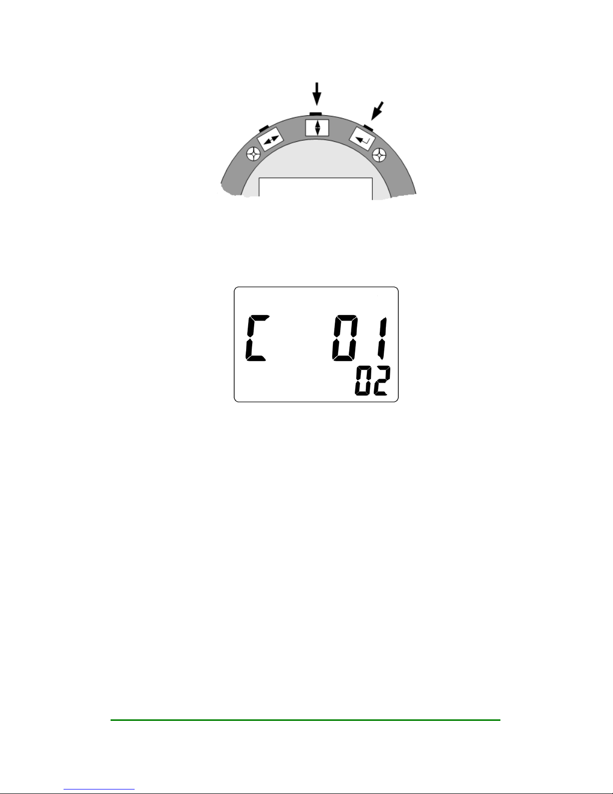
5.1.1 Code setting
Under working status, to enter code setting, please hold “Enter button” then press “U-D button” at the
same time. Please reference to picture 5.1.
User’s Manual Rev1.0
Date:15/07/2015 User’s Manual
20/47
Picture 5.1 enter and quit code setting
When in code setting, the first row will display the reference number of the code setting, and the
lower row will display the contents of this parameter. The digit that is flashing is the digit under
setting. Please reference to picture 5.2, which means C01=02, that is set the pre-heating time to 2
seconds.
Picture 5.2 code setting
When under code setting, Now ,user can use “L-R button” to choose which digit on the displayer
are to be set , and use “R-D button” to switch the digit to 0~9 . The first time of pressing “Enter
button” means to set the lower row, when under this situation, users can still use “L-R button” or
“U-D button” to set. Press “Enter button” again to check if the setting is available. If setting is
available, the display will not flash, when user can still press “L-R button” or “U-D button” to set
again. When display is not flashing, pressure “Enter button” to save and go to next setting.
If want to quit code setting, same as entering, please hold “Enter button” then press “U-D button”
at the same time.
5.1.2 Digital setting
Under working status, to enter code setting, please hold “Enter button” then press “L-R button” at the
same time. Please reference to picture 5.3.
Table of contents
Other Nitto Measuring Instrument manuals


Popular Measuring Instrument manuals by other brands

Freiberg Instruments
Freiberg Instruments lexsyg research MANUAL AND DOCUMENTATION

Wallbox
Wallbox MID METER installation guide

XONOX
XONOX CT 200 Quality assurance document

Hanna Instruments
Hanna Instruments HI 88703 instruction manual

Roughneck
Roughneck 24923 owner's manual

Elenco Electronics
Elenco Electronics TWT-1 instruction manual


