Beamreach networks BeamPlex BRU-100 Instruction Manual

BeamPlex
BRU-100 and BRU-150
Remote Unit
Installation and
Maintenance
Service Utilities
1106333-01
Rev. 3
Nov. 2003

ii
Legal Notices
This document is published in association with the products of BeamReach Networks Incorporated.
Due to ongoing product development and improvements, BeamReach Networks makes no
representations or warranties with respect to the accuracy or completeness of this document and
reserves the right to make changes without notice.
Patents
Products and technologies described herein include those covered by one or more U.S. patents owned
by BeamReach Networks Incorporated.
Copyrights
© 2003 BeamReach Networks Incorporated. All rights reserved. No part of this document may be
copied, photocopied, reproduced, translated, or reduced to any electronic medium or machine-
readable form without prior written consent from BeamReach Networks Incorporated.
Printed in the United States of America.
Trademarks
BeamPlex and Adaptive MultiBeam OFDM are trademarks of BeamReach Networks Incorporated.
All other brand names are trademarks of their respective holders.
Revision History
Document number 1106333-01
This document applies to System Software versions subsequent to that which is listed here, unless the
document is reissued due to software feature upgrades. The software release notes will indicate the
applicable document revision level.
BeamReach Networks
755 North Mathilda Ave.
Sunnyvale, CA 94086
408.869.8700
www.BeamReachNetworks.com
Revision Status Revision Level Date System Release
Pre-Production Rev 1 April 2003 1.1
Pre-Production Rev 2 June 2003 1.1
Pre-Production Rev 3 November 2003 1.1

1106333-01 Pre-Production iii
Revision 3
Table of Contents
Chapter 1 – Introduction . . . . . . . . . . . . . . . . . . . . . . . . . . . . . . . . . . . . . . . . . . . . . . . 1
Overview . . . . . . . . . . . . . . . . . . . . . . . . . . . . . . . . . . . . . . . . . . . . . . . . . . . . . . . . . . . . . . . . . . . . . . . 2
Scope and Purpose . . . . . . . . . . . . . . . . . . . . . . . . . . . . . . . . . . . . . . . . . . . . . . . . . . . . . . . . . . . . 2
Important Notices . . . . . . . . . . . . . . . . . . . . . . . . . . . . . . . . . . . . . . . . . . . . . . . . . . . . . . . . . . . . . 3
Remote Unit Models . . . . . . . . . . . . . . . . . . . . . . . . . . . . . . . . . . . . . . . . . . . . . . . . . . . . . . . . . . . 3
Remote Unit Service Utilities . . . . . . . . . . . . . . . . . . . . . . . . . . . . . . . . . . . . . . . . . . . . . . . . . . . . . . . 5
BRU Installation Tool (BRUIT) . . . . . . . . . . . . . . . . . . . . . . . . . . . . . . . . . . . . . . . . . . . . . . . . . .5
BRU Status Monitor . . . . . . . . . . . . . . . . . . . . . . . . . . . . . . . . . . . . . . . . . . . . . . . . . . . . . . . . . . . 5
BRU-150 Transceiver Features . . . . . . . . . . . . . . . . . . . . . . . . . . . . . . . . . . . . . . . . . . . . . . . . . . . . . . 6
Installation Overview . . . . . . . . . . . . . . . . . . . . . . . . . . . . . . . . . . . . . . . . . . . . . . . . . . . . . . . . . . . . . . 8
BRU-150 Self-Install Remote Unit . . . . . . . . . . . . . . . . . . . . . . . . . . . . . . . . . . . . . . . . . . . . . . . .8
BRU-100 Professional Install Remote Unit . . . . . . . . . . . . . . . . . . . . . . . . . . . . . . . . . . . . . . . . . 8
Reference Documents . . . . . . . . . . . . . . . . . . . . . . . . . . . . . . . . . . . . . . . . . . . . . . . . . . . . . . . . . . . . . 9
Chapter 2 – Preparation . . . . . . . . . . . . . . . . . . . . . . . . . . . . . . . . . . . . . . . . . . . . . . 11
Service Computer . . . . . . . . . . . . . . . . . . . . . . . . . . . . . . . . . . . . . . . . . . . . . . . . . . . . . . . . . . . . . . . . 12
Computer . . . . . . . . . . . . . . . . . . . . . . . . . . . . . . . . . . . . . . . . . . . . . . . . . . . . . . . . . . . . . . . . . . . 12
Ethernet Cable . . . . . . . . . . . . . . . . . . . . . . . . . . . . . . . . . . . . . . . . . . . . . . . . . . . . . . . . . . . . . . . 12
IP Address . . . . . . . . . . . . . . . . . . . . . . . . . . . . . . . . . . . . . . . . . . . . . . . . . . . . . . . . . . . . . . . . . . 13
Software . . . . . . . . . . . . . . . . . . . . . . . . . . . . . . . . . . . . . . . . . . . . . . . . . . . . . . . . . . . . . . . . . . . . . . . 13
Service Utilities . . . . . . . . . . . . . . . . . . . . . . . . . . . . . . . . . . . . . . . . . . . . . . . . . . . . . . . . . . . . . . 13
Software Image . . . . . . . . . . . . . . . . . . . . . . . . . . . . . . . . . . . . . . . . . . . . . . . . . . . . . . . . . . . . . . 13
Service Order File . . . . . . . . . . . . . . . . . . . . . . . . . . . . . . . . . . . . . . . . . . . . . . . . . . . . . . . . . . . . 14
BRU-100 . . . . . . . . . . . . . . . . . . . . . . . . . . . . . . . . . . . . . . . . . . . . . . . . . . . . . . . . . . . . . . . 14
BRU-150 . . . . . . . . . . . . . . . . . . . . . . . . . . . . . . . . . . . . . . . . . . . . . . . . . . . . . . . . . . . . . . . 14
Equipment and Material . . . . . . . . . . . . . . . . . . . . . . . . . . . . . . . . . . . . . . . . . . . . . . . . . . . . . . . . . . . 17
Chapter 3 – Installation Tool . . . . . . . . . . . . . . . . . . . . . . . . . . . . . . . . . . . . . . . . . . 19
Preface . . . . . . . . . . . . . . . . . . . . . . . . . . . . . . . . . . . . . . . . . . . . . . . . . . . . . . . . . . . . . . . . . . . . . . . . 20
BRU-150 Pre-Configuration . . . . . . . . . . . . . . . . . . . . . . . . . . . . . . . . . . . . . . . . . . . . . . . . . . . .20
Antenna Location . . . . . . . . . . . . . . . . . . . . . . . . . . . . . . . . . . . . . . . . . . . . . . . . . . . . . . . . . . . . 21
Installation Tool Operation . . . . . . . . . . . . . . . . . . . . . . . . . . . . . . . . . . . . . . . . . . . . . . . . . . . . . . . . 22
Step 1 Physical Installation . . . . . . . . . . . . . . . . . . . . . . . . . . . . . . . . . . . . . . . . . . . . . . . . . . . 22
LAN Connection . . . . . . . . . . . . . . . . . . . . . . . . . . . . . . . . . . . . . . . . . . . . . . . . . . . . . . . . .23
Step 2 Login . . . . . . . . . . . . . . . . . . . . . . . . . . . . . . . . . . . . . . . . . . . . . . . . . . . . . . . . . . . . . . . 23
Step 3 Status Check . . . . . . . . . . . . . . . . . . . . . . . . . . . . . . . . . . . . . . . . . . . . . . . . . . . . . . . . . 24
BRU Configuration . . . . . . . . . . . . . . . . . . . . . . . . . . . . . . . . . . . . . . . . . . . . . . . . . . . . . . .25
BRU Software Upload . . . . . . . . . . . . . . . . . . . . . . . . . . . . . . . . . . . . . . . . . . . . . . . . . . . . . 25
Step 4 Antenna Pointing Calculations . . . . . . . . . . . . . . . . . . . . . . . . . . . . . . . . . . . . . . . . . . . 27
Calculate Base Station Direction . . . . . . . . . . . . . . . . . . . . . . . . . . . . . . . . . . . . . . . . . . . . . 27
Coordinates . . . . . . . . . . . . . . . . . . . . . . . . . . . . . . . . . . . . . . . . . . . . . . . . . . . . . . . . . . . . . 28

Remote Unit Installation
Service Utilities Table of Contents
1106333-01 Pre-Production iv
Revision 3
Step 5 Antenna Pointing . . . . . . . . . . . . . . . . . . . . . . . . . . . . . . . . . . . . . . . . . . . . . . . . . . . . .29
Background Information . . . . . . . . . . . . . . . . . . . . . . . . . . . . . . . . . . . . . . . . . . . . . . . . . . . 29
Working the GUI . . . . . . . . . . . . . . . . . . . . . . . . . . . . . . . . . . . . . . . . . . . . . . . . . . . . . . . . .30
Signal Strength Details . . . . . . . . . . . . . . . . . . . . . . . . . . . . . . . . . . . . . . . . . . . . . . . . . . . .31
Message Log . . . . . . . . . . . . . . . . . . . . . . . . . . . . . . . . . . . . . . . . . . . . . . . . . . . . . . . . . . . . 32
Step 6 Service Activation . . . . . . . . . . . . . . . . . . . . . . . . . . . . . . . . . . . . . . . . . . . . . . . . . . . . . 33
Step 7 IP Address . . . . . . . . . . . . . . . . . . . . . . . . . . . . . . . . . . . . . . . . . . . . . . . . . . . . . . . . . . . 34
Step 8 Installation Status . . . . . . . . . . . . . . . . . . . . . . . . . . . . . . . . . . . . . . . . . . . . . . . . . . . . . 35
Other Technical Features . . . . . . . . . . . . . . . . . . . . . . . . . . . . . . . . . . . . . . . . . . . . . . . . . . . . . . . . . . 36
Default Configuration Button . . . . . . . . . . . . . . . . . . . . . . . . . . . . . . . . . . . . . . . . . . . . . . . . . . . 36
Shortcut Menu . . . . . . . . . . . . . . . . . . . . . . . . . . . . . . . . . . . . . . . . . . . . . . . . . . . . . . . . . . . . . . . 36
Chapter 4 – Status Monitor . . . . . . . . . . . . . . . . . . . . . . . . . . . . . . . . . . . . . . . . . . . . 39
Overview . . . . . . . . . . . . . . . . . . . . . . . . . . . . . . . . . . . . . . . . . . . . . . . . . . . . . . . . . . . . . . . . . . . . . . 40
Status Monitor Displays . . . . . . . . . . . . . . . . . . . . . . . . . . . . . . . . . . . . . . . . . . . . . . . . . . . . . . . . . . . 41
Signal Strength Monitor . . . . . . . . . . . . . . . . . . . . . . . . . . . . . . . . . . . . . . . . . . . . . . . . . . . . . . . 41
IP Address Setting . . . . . . . . . . . . . . . . . . . . . . . . . . . . . . . . . . . . . . . . . . . . . . . . . . . . . . . . . . . . 43
Diagnostics . . . . . . . . . . . . . . . . . . . . . . . . . . . . . . . . . . . . . . . . . . . . . . . . . . . . . . . . . . . . . . . . . 44
Appendix A – Remote Unit Specifications . . . . . . . . . . . . . . . . . . . . . . . . . . . . . . . . 45
Functional Characteristics . . . . . . . . . . . . . . . . . . . . . . . . . . . . . . . . . . . . . . . . . . . . . . . . . . . . . . 46
User Throughput . . . . . . . . . . . . . . . . . . . . . . . . . . . . . . . . . . . . . . . . . . . . . . . . . . . . . . . . . . . . . 46
Radio Characteristics . . . . . . . . . . . . . . . . . . . . . . . . . . . . . . . . . . . . . . . . . . . . . . . . . . . . . . . . . 46
Antenna Characteristics . . . . . . . . . . . . . . . . . . . . . . . . . . . . . . . . . . . . . . . . . . . . . . . . . . . . . . . 47
Physical Characteristics . . . . . . . . . . . . . . . . . . . . . . . . . . . . . . . . . . . . . . . . . . . . . . . . . . . . . . . 47
Physical Dimensions . . . . . . . . . . . . . . . . . . . . . . . . . . . . . . . . . . . . . . . . . . . . . . . . . . . . . . . . . . 47
Environmental Characteristics . . . . . . . . . . . . . . . . . . . . . . . . . . . . . . . . . . . . . . . . . . . . . . . . . . 47
Regulatory Compliance . . . . . . . . . . . . . . . . . . . . . . . . . . . . . . . . . . . . . . . . . . . . . . . . . . . . . . . 48
Index . . . . . . . . . . . . . . . . . . . . . . . . . . . . . . . . . . . . . . . . . . . . . . . . . . . . . . . . . . . . . . 49

1106333-01 Pre-Production v
Revision 3
List of Figures
Chapter 1 – Introduction
Figure 1-1 Remote Unit Models . . . . . . . . . . . . . . . . . . . . . . . . . . . . . . . . . . . . . . . . . . . . . . . . . . . 4
Figure 1-2 Transceiver Front Panel . . . . . . . . . . . . . . . . . . . . . . . . . . . . . . . . . . . . . . . . . . . . . . . . 6
Figure 1-3 Transceiver Rear Panel . . . . . . . . . . . . . . . . . . . . . . . . . . . . . . . . . . . . . . . . . . . . . . . . . 7
Chapter 2 – Preparation
Figure 2-1 Service Order File Contents . . . . . . . . . . . . . . . . . . . . . . . . . . . . . . . . . . . . . . . . . . . . 16

vi Pre-Production 1106333-01
Revision 3

1106333-01 Pre-Production 1
Revision 3
CHAPTER
1
Introduction
In This Chapter:
Overview, page 2
Remote Unit Service Utilities, page 5
BRU-150 Transceiver Features, page 6
Installation Overview, page 8
Reference Documents, page 9
This chapter introduces the service utilities for the
BRU-100 and BRU-150 Remote Unit. It also provides
reference information regarding the installation
process.

Ch. 1 Introduction Remote Unit Installation
Overview Service Utilities
2 Pre-Production 1106333-01
Revision 3
Overview
This section describes the intended use of this document and introduces
the service utilities used for remote unit installation and maintenance.
A remote unit is the subscriber termination equipment for the BeamPlex
broadband wireless access system. It communicates with its associated
base station through an RF signal path; and it communicates with the
subscriber’s computer through an Ethernet cable.
The service utilities are used to set configuration parameters, initiate the
phases of service activation, and monitor the status of a remote unit.
Scope and Purpose
The service utilities are applicable for professional installation and
diagnosis of both the BRU-150 and BRU-100 models of remote unit, which
are described below. Both models are designed with the same electronics so
the service utilities will work with either one of them.
Caution: Read the section BRU-150 Self-Install Remote Unit on page 8
about required configuration before delivery to the subscriber.
This document is primarily for technicians who perform a manual BRU-
150 installation. The BRU-150 is designed for subscriber self-installation.
If the subscriber encounters problems during or after self-installation,
technicians will use these service utilities to resolve the problems.
For system release 1.1, the existing installation manuals listed in the
section Reference Documents on page 9 accurately describe the physical
installation process. However, the BRU-100 documents describe the use of
the RIT (Remote Unit Installation Tool) which has now been replaced by
the service utilities described here. Installers should use this document for
configuring the BRU-100 until the installation manuals have been revised.

Remote Unit Installation Ch. 1 Introduction
Service Utilities Overview
1106333-01 Pre-Production 3
Revision 3
Important Notices
Warning: This device is a radio frequency transmitter. It is required to comply
with FCC RF exposure requirements for transmitting devices. A
minimum separation distance of 8 inches (20 cm) or more must be
maintained between the antenna and all persons during device
operations to ensure compliance with the FCC's rules for Radio
Frequency Exposure. If this minimum distance cannot be
maintained, exposure to RF levels that exceed the FCC's limits may
result. This equipment must not be co-located with any other
transmitting antenna.
Note: This equipment has been tested and found to comply with the limits
for a Class B digital device, pursuant to Part 15 of the FCC Rules.
These limits are designed to provide reasonable protection against
harmful interference in a residential installation. This equipment
generates, uses, and can radiate radio frequency energy and, if not
installed and used in accordance with the instructions, may cause
harmful interference to radio communications. However, there is no
guarantee that interference will not occur in a particular installation.
If this equipment does cause harmful interference to radio or
television reception, which can be determined by turning the
equipment off and on, the user is encouraged to try to correct the
interference by one or more of the following measures:
– Reorient or relocate the receiving antenna.
– Increase the separation between the equipment and the receiver.
– Connect the equipment into an outlet on a circuit different from
that to which the receiver is connected.
– Consult the dealer or an experienced radio/TV technician for help.
Note: Any changes or modifications to this equipment that are not
approved by BeamReach Networks could void your authority to
operate the equipment if such changes or modifications affect the
regulatory compliance specified in Appendix A.
Remote Unit Models
The BeamPlex Broadband Wireless Access System offers two models of
remote units for CPE, as shown in Figure 1-1:

Ch. 1 Introduction Remote Unit Installation
Overview Service Utilities
4 Pre-Production 1106333-01
Revision 3
Figure 1-1 Remote Unit Models
SD 008
Power
Adapter
BRU-150
Transceiver
Antenna
BRU-150
BRU-100
SD 017
Outdoor Unit
(ODU)
Service
Interface Box
(optional)
Power Injector
Power Adapter
Ground
Wire
Ground Rod
Self-install, Indoor Unit
Professional-install, Outdoor Unit

Remote Unit Installation Ch. 1 Introduction
Service Utilities Remote Unit Service Utilities
1106333-01 Pre-Production 5
Revision 3
Remote Unit Service Utilities
The service utilities are two applets designed to support the installation
and maintenance of a remote unit:
BRU Installation Tool (BRUIT)
The installation tool consists of a set of GUI windows that guide the
installer through the steps of the configuration and activation process.
Latitude/longitude coordinates of the subscriber’s premise and compass
bearings to the closest base stations are used to accurately point the
antenna in areas of difficult reception. The GUI contains a signal
strength indicator and other technical displays. Installers can set
certain configuration parameters and install software upgrades with
this tool.
The BRUIT is used primarily for BRU-100 professional installations. It
is also used for onsite technical support if a subscriber encounters
problems with either model of remote unit.
BRU Status Monitor
The status monitor displays information about the state of the air link
between the remote unit and the base station. It provides a utility to
change the IP address in the remote unit, and it performs a basic
continuity check between the PC and the remote unit, and between the
PC and base station.
The status monitor utility is part of the service utilities, but it was
designed for the subscriber and is installed on their computer.

Ch. 1 Introduction Remote Unit Installation
BRU-150 Transceiver Features Service Utilities
6 Pre-Production 1106333-01
Revision 3
BRU-150 Transceiver Features
This section introduces the physical features of the displays and
connections on the BRU-150 Transceiver.
The BRU-150 is designed for the subscriber, so its displays and controls are
designed for simple functionality.
Figure 1-2 Transceiver Front Panel
SIGNAL
STRENGTH
AIR LINK
SYNC
LEDs illuminate progressively
from the bottom up as the
signal strength increases.
Each LED also has three stages:
· Slow blink at lowest signal
· Fast blink at medium signal
· Solid at highest signal
Solid green when
authentication completes.
Red while unit is booting up.
Flashing amber while unit auto-searches
for a base station.
Solid green when synchronization and
ranging completes.
Flickers green when data is being passed.
Solid amber if synchronization did not
complete.
Default configuration button
recessed behind front panel.
· Cycles power to the unit
· Sets IP address to 192.168.1.1
· Sets subnet to 255.255.255.0
· Sets BSOC to -1
Use a paper clip or
similar object to actuate
the reset button.
IDU001
Flickers green when data
is being passed.

Remote Unit Installation Ch. 1 Introduction
Service Utilities BRU-150 Transceiver Features
1106333-01 Pre-Production 7
Revision 3
Figure 1-3 Transceiver Rear Panel
DATA
ANTENNA
48V .7A
Ethernet
Green LED -- Flickers when data is being passed.
Amber LED -- Steady when Ethernet link is established.
Flickers when data is being passed
Power
IDU 002

Ch. 1 Introduction Remote Unit Installation
Installation Overview Service Utilities
8 Pre-Production 1106333-01
Revision 3
Installation Overview
This section overviews the installation steps for the BRU-150 and BRU-100
remote units.
BRU-150 Self-Install Remote Unit
The BRU-150 is designed for the subscriber to self-install the unit.
However, for system release 1.1 the configuration process has not been fully
automated. You must manually set the Local RUID (remote unit
identification) before delivering the unit to the subscriber. This parameter
uniquely identifies this remote unit to the base station.
Prior to sending the remote unit to a subscriber, you must determine the
Local RUID that will be assigned to this unit. Your company should have
developed a plan for Local RUID assignment.
Note: The Local RUID is normally associated with a particular
subscriber. You must ensure the correct BRU-150 is being
delivered to a subscriber based on the Local RUID assignment.
The Local RUID is configured into the Transceiver of the BRU-150 with
the BRUIT (installation tool). At Step 3 in the BRUIT you will open the
BRU Configuration window and set a value for the Local RUID.
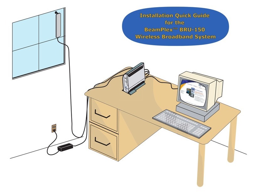
The subscriber will use the BRU-150 Installation Quick Guide to
accomplish the installation. If a subscriber is in an area with difficult
reception, you may need to make a service call to perform a manual
installation using precise antenna-pointing techniques.
BRU-100 Professional Install Remote Unit
The installation process for the BRU-100 is described in detail in the
installation documents listed in the following section. The service utilities
are used in place of the RIT (Remote Unit Installation Tool) currently
described in those documents.

Remote Unit Installation Ch. 1 Introduction
Service Utilities Reference Documents
1106333-01 Pre-Production 9
Revision 3
Reference Documents
The following technical publications from BeamReach Networks describe
the installation process for the two remote unit models:
♦BRU-150 Installation Quick Guide, 1106333-02
♦BRU-100 Installation and Configuration, 1106138-01
♦BRU-100 Installation Summary, 1106138-03

10 Pre-Production 1106333-01
Revision 3

Ch. 2 Preparation Remote Unit Installation
Service Computer Service Utilities
12 Pre-Production 1106333-01
Revision 3
Service Computer
This section describes the requirement for the service computer that will
host the service utilities and be used in the field to install remote units.
These requirements also apply to the subscriber’s computer.
Computer
The service utilities are designed to run on a computer with a Windows
2000 or later operating system. For field service, a portable (laptop)
computer is used.
The computer must be configured with
–an Ethernet (NIC) card,
–a PPPoE client, and;
–a CD drive.
Ethernet Cable
The service computer connects to the remote unit through an Ethernet
cable.
BRU-150
Use a CAT 5 Ethernet straight-thru cable with RJ-45 plug (male)
connectors on both ends to connect the computer to a BRU-150 Transceiver.
BRU-100
For the current version of the BRU-100 remote unit, a cable is supplied
with the installation kit that mates with the round connector on the
Outdoor Unit and has an RJ-45 connector on the other end. You will need
this cable and the installation power injector to connect the service
computer to the Outdoor Unit. Follow the instructions in the BRU-100
Installation and Configuration manual, or the Installation Summary
guide, using the service computer in place of the RIT.
The next version of the BRU-100 will have a standard RJ-45 jack in place of
the round connector, and the installation power injector will not be needed.

Remote Unit Installation Ch. 2 Preparation
Service Utilities Software
1106333-01 Pre-Production 13
Revision 3
IP Address
The service computer must have a static IP address that is compatible with
the remote unit’s address, which is delivered with the default address of
192.168.1.1. Set the IP address in the service computer as follows:
♦IP address 192.168.1.X
Where X is any number between 2 and 255. If the number you
choose causes a conflict with another network device, you will see an
error message. If this occurs, try a different number for the X value.
♦Subnet mask 255.255.255.0
Software
This section lists the software files you must load onto the service
computer prior to a service call.
Service Utilities
The service utilities are not packaged in an installation shield at this time.
The files are delivered in a self-extracting Zip file (bruit.exe) on a CD.
Create a new directory on the service computer and unzip the files into it.
Open the applications by executing these files:
♦BRU-IT.exe – BeamPlex Remote Unit Installation Tool
♦BRU-Mon.exe – BeamPlex Remote Unit Monitor
You may to create shortcuts to these files for ease of use.
Software Image
You must also download and store the current remote unit software image
file, which contains updates to the operating system. Step 3 in the
installation tool allows you to read the software version currently in the
remote unit, and to send a new image file if an update is indicated.
A software image file is provided by BeamReach Networks and should be
stored in your system on a TFTP server.

Ch. 2 Preparation Remote Unit Installation
Software Service Utilities
14 Pre-Production 1106333-01
Revision 3
Service Order File
A service order file is generated by the SAM (Service Activation Module) of
the BeamPlex Element Management System. The service provider inputs
customer data into the SAM for each BRU-100 subscriber.
BRU-100
For a BRU-100 installation, you must also download a service order file for
each subscriber who will receive an installation on the pending service
trip. This file contains the subscriber’s latitude and longitude estimated
coordinates and the coordinates of the closest base stations. This data is
retrieved when you enter the customer number in Step 4 of the installation
procedure. The customer number is the numeric part of the service order
file name. For example, service order file SO_567891.xml denotes a customer
number of 567891.
BRU-150
A service order file may not exist for a subscriber with a BRU-150. You will
need a file only if you have to perform a manual installation. In this case,
there is a default service file included with installation tool that can be
used. Its file name is SO_1467854.xml and it is in the same directory in the
service computer as the installation tool files.
Edit this default file to change the following data:
–BSOC (base station offset code) – The remote unit uses this code to
identify a base station.
–Base station coordinates – The latitude/longitude coordinates of the
three closest base stations in your service area.
Note: You must obtain the BSOC and coordinates from the engineers
that configured the base station.
This XML file can be easily edited with a text editor, such as the Notepad
or Wordpad applications that come standard with Windows operating
systems.
A portion of the service order file as read by a text editor is shown in
Figure 2-1 on page 16. The file contains data on three base stations.
This manual suits for next models
1
Table of contents
Other Beamreach networks Microphone System manuals
Popular Microphone System manuals by other brands
IMG STAGE LINE
IMG STAGE LINE TXS-626 instruction manual
Rocket Fish
Rocket Fish RF-WHTIB-A Quick setup guide

IMG STAGE LINE
IMG STAGE LINE TXS-142/VT instruction manual
IMG STAGE LINE
IMG STAGE LINE STAGE LINE TXS-100SET B instruction manual
IMG STAGE LINE
IMG STAGE LINE TXS-727 instruction manual

Beyerdynamic
Beyerdynamic Opus 100 operating instructions

