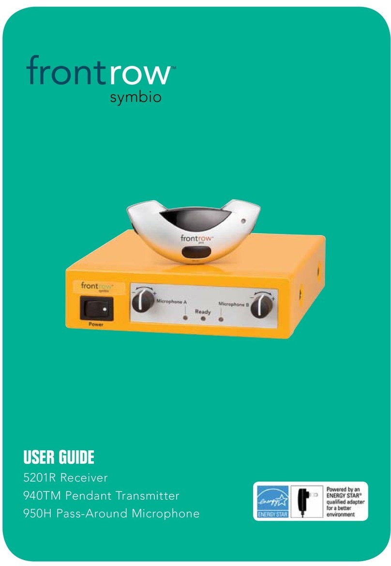
FrontRow symbio 5201R Assembly instructions

INSTALLER GUIDE
5201R Receiver
symbio

Contents
Electrical Warnings ........................................................1
Receiver Components......................................................2
Chapter 1 Installation ..................................................3 - 5
Chapter 2 Get Your FrontRow Symbio Parts Ready.........................6 - 7
Chapter 3 Get Yourself Ready..............................................8
Chapter 4 Plan Your Sensor Installation..................................9 - 12
Chapter 5 Installing Sensors ..............................................13 - 16
Chapter 6 Install the Receiver.............................................17 - 20
Chapter 7 Adjust the Amplifier............................................... 21
Chapter 8 Test System ...................................................22
Chapter 9 Product Specifications ..........................................23
Chapter 10 Troubleshooting ...............................................24
Chapter 11 Regulatory ....................................................25

1
1. Avoid Abuse to the Power Supply
To reduce risk of electric shock, unplug
the power supply from outlet before
attempting any maintenance or cleaning.
Turning off controls will not reduce this risk.
DO NOT disassemble the power supply.
Return the apparatus to FrontRow for
qualified service and repair if service
or repair is required. Incorrect reassembly
may result in a risk of electric shock
or fire.
DO NOT expose the power supply to
rain, snow, water, gas, oil, etc.
DO NOT operate the power supply
if it has received a sharp blow, been
dropped, or otherwise damaged in any
way; return the apparatus to FrontRow
for qualified service and repair.
DO NOT block or cover the apparatus
and impede ventilation.
2. Proper Use of the Power Supply
and Wiring
An extension cord should not be used
unless absolutely necessary. Use of
improper extension cord could result
in a risk of fire and electric shock. The
cord MUST be plugged into a grounded
outlet. Make sure it is properly wired, in
good electrical condition, and wire size
is large enough for AC ampere rating of
the power supply or charger as specified by
FrontRow. AWG = American Wire Gauge.
To reduce risk of damage to plug and
cord when disconnecting the power
supply or charger, ALWAYS pull on plug
- NEVER on cord.
Locate cord so that it will not be
stepped on, tripped over, or otherwise
subject to damage or stress. DO NOT
lay extension cord on charger.
DO NOT operate the power supply
with damaged cord or plug - replace
them immediately.
ELECTRICAL WARNINGS
!
ELECTRICAL SAFETY
INFORMATION:
PRECAUTIONS & SAFETY
RECOMMENDATIONS
Follow Manufacturers' Recommendations
Before using the receiver and power supply,
read all instructions for, and caution markings
on the receiver and power supply and in this
installation guide.

2
Receiver Components
Receiver
1. Receiver
2. Infrared ceiling sensor*
3. Receiver power supply
4. Receiver mounting tray (optional)
1
4
2
3
*Not necessary if FrontRow IR speakers are already installed

1Installation
Before you begin your installation
Make sure you've got everything you need to set up your FrontRow Symbio system.
By taking a few minutes to prepare, you'll help ensure the actual set-up is as quick and
problem-free as possible.
General safety precautions
• Do not install or use the receiver near water or heat sources
• Clean only with a dry cloth
• Do not block any ventilation openings
• Protect all cables from wear and damage from foot traffic, doors, and other hazards
• Use only accessories specified by FrontRow
• Refer servicing to qualified service personnel
• Wear safety goggles when using power tools
• Follow all safety guidelines when using ladders
• Observe your local building, electrical, and fire codes when installing any
electrical equipment
Does your system meet the classroom requirements?
Check the table below to confirm that your classroom is set up properly for the
Frontrow Symbio system you have. In most cases one ceiling sensor will be suf-
ficient. However, some classrooms may require one or more additional sensors for
optimal room coverage. While other classroom configurations may work with your
Frontrow Pro Symbio system, we can only support those listed below.
Size
Walls
Windows
Obstructions
(hanging art, tall free-
standing bookshelves,
suspended lights)
Shape
< 900ft2
Light colors
Few
Few
Simple
900ft2 - 1500ft2
Dark colors
Many (>50% window-to-wall area)
Many
Complex
(Alcoves/bays where teachers may walk)
______ x 1 +______ x 3 =
If your score is: We recommend:
< = 5 1 ceiling sensor
> 5 2 wall* OR 2 ceiling sensors
*Wall sensors can help where there are ceiling obstructions (hanging lights, artwork, etc.)
(Square, Rectangle)
Total
Checked Total
Checked
3

4
Are your existing speakers a feedback risk?
It's very important to assess the position of existing speakers — and move them if necessary — to
avoid creating acoustic feedback. Confirm before your begin that your speakers are positioned
according to these guidelines:
a Installing ceiling speakers?
Install speakers only over the area where students are sitting — not the entire room.
Avoid installing speakers directly in front of the white board — this not only covers an
area not used by students but increases the chance of feedback.
Each speaker fully covers
one-fourth of student
listening area
Avoid covering area in
front of white board
Install speakers in ceil-
ing tiles centered over
one-fourth of the stu-
dent listening area
Correct
✔
Inadequate coverage of
student listening area
Too much coverage in
front of white board
(feedback risk)
Incorrect
✘

5
b Installing IR speakers?
Install speakers only over the area where students are sitting — not the entire room.
Speakers should only be placed on the side walls of the classroom.
Walls should have a space approximately 10in wide by 5in tall (25 x 13cm) to solidly mount the
wall bracket.
Avoid installing speakers directly in front of the white board — this not only covers an area not
used by students – but increases the chance of feedback.
Correct
✔
Inadequate coverage of
student listening area
Too much coverage
in front of white board
(feedback risk)
Incorrect
✘
seating area centerline
White board
Speaker too close to white
board (feedback risk)
Inadequate coverage of
student listening area

6
2Get Your FrontRow Symbio Parts Ready
Check the contents of your FrontRow Symbio installation kit against the parts listed
below. To help you stay organized, we recommend that you keep the parts needed for
each step separate.
1. Open your main component box
940TM microphone
+
AA (LR6) NiMH
Rechargeable Batteries
(silver sleeve)
+
Aux-in Cord
+
5201R Symbio Receiver
+
*Not needed if FrontRow IR speakers
have been installed prior
Power Supply
940CS Ceiling Sensor
with mounting bracket*
+
Sensor Cable
Two Unit Charger
950H Mic
+
AA (LR6) NiMH
Rechargeable Batteries
(silver sleeve)
+
OR
Aux-in Cord

7
2. Open your RMS Kit (for use with ezRoom)
Adapter Cable
RJ45-RJ45 Adapter
UTP CAT 5e Cable
Volume Setting Label
When using Symbio with ezRoom setup, turn both volume
controls to maximum setting
Please DO NOT change these volume settings

8
3Get Yourself Ready
Nearly everything you need to install your FrontRow Symbio system is included in the
boxes we shipped. You will need some basic tools and materials, depending on how
your classroom is built:
1. What kind of walls do you have?
For drywall installations (similar to most houses) gather the following tools:
Drill Wall anchors
Drill bits Cable tacks/staples
Phillips #2 driver bit Plastic cable (zip) ties
Level or ruler/tape measure Plastic raceway with screws
Crimp pliers or scissors Tin snips (optional)
Hammer Ladder
Staple gun Safety goggles
For concrete walls, assemble the following tools:
Hammer drill Hammer
Masonry drill bits Plastic cable (zip) ties
Phillips #2 driver bit Plastic raceway with adhesive
Level or ruler/tape measure Tin snips (optional)
Crimp pliers or scissors Ladder
Concrete screws Safety goggles

9
SENSOR & SENSOR CABLE
The sensor and sensor cable are critical elements in the system and the most
sensitive to electrical noise.
a. DO NOT shorten OR lengthen the sensor cable. Its factory-specified length is
critical to the performance of the system.
b. DO NOT use a splitter with the sensor cable.
c. DO NOT use a different cable.
d. DO NOT alter the RCA connectors on the cable.
e. AVOID routing the sensor cable next to other cables or electrical systems (e.g.,
other electrical conduit, Ethernet cable, video cable, fluorescent light ballast, etc.).
Leave at least 6 in. (15cm) space around the sensor cable.
f. Excess cable can be coiled, tied and placed safely in a plenum space. DO NOT
place the sensor coil near other cables or electrical systems (e.g., other electrical
conduit, Ethernet cable, video cable, fluorescent light ballast, etc.).
g. Route the sensor cable AWAY from speaker wires as far as practical. We
recommend leaving at least 6 in. (15cm) between the two whenever possible.
h. Local regulations may require plenum-rated cable if used in a plenum space.
Sensor cable supplied with your system is plenum rated.
4 Plan Your Sensor Installation
(Skip this section if FrontRow IR speakers have been installed previously)
Sensor Mounting
Assessing the individual characteristics of the environment is critical to achieving the
best performance. Poor coverage planning can dramatically reduce the performance
of the system.
a. DO NOT mount the ceiling sensor or wall sensors in direct sunlight as it will greatly
reduce performance.
b. The ceiling sensor must have a clear view of the coverage area and must be
mounted parallel to the floor to function optimally (figure 1). If drop lights are used
in the room, wall sensors may be a better option. Or, a drop mount* may be used to
lower the ceiling sensor.
Light
Fixture
Ceiling Sensor
Orientation and coverage
optimized
*
*not supplied by FrontRow
Classroom
Ceiling
Sensor
XSensor performance reduced: Not parallel
to floor AND blocked by light fixtures.
Figure 1: Ceiling Sensor Installation
Sensor cable
Receiver
Amplifier

10
Plan Your Sensor Installation (cont.)
Interference and IR Coverage
The FrontRow Symbio system uses infrared light to transmit the voice signal from the microphone
to the sensor in the ceiling/wall sensors. Proper placement of the sensors is critical for optimal
system performance.
a. Adjacent classrooms that use FrontRow infrared systems can interfere with each other if the
rooms are separated by windows. The windows allow the infrared light to “escape” from the
classroom only to be picked up by the sensors in the adjacent classroom, causing interference
and “cross talk”. Be sure to recommend window coverings to the greatest extent practical
when using the system.
b. Direct sunlight can reduce system performance. Be sure to recommend window coverings to
the greatest extent practical when using the system.
c. Infrared light has better reflection off of white and glossy surfaces. The ceiling sensor can be
placed to help provide coverage in areas where the signal may be weak due to insufficient
infrared reflection.

11
Installing one ceiling sensor
Mentally divide the room into quarters and locate the center of the room as shown.
Use a piece of tape to mark a spot on the ceiling in the center of the room.
NOTE: The sensor must be able to "see" the entire room — do not block the sensor
with projector mounts, lighting, hanging art, or other obstructions. If the teacher can
see the sensor from all parts of the room, you've probably chosen a good spot.
1. Positioning a ceiling sensor
Sensor symbols:
= ceiling sensor
Plan Your Sensor Installation (cont.)
Installing two ceiling sensors
Mentally divide the room into half and locate the center of each half as shown.
Use a piece of tape to mark the spots in each half of the room.
NOTE: The sensor must be able to "see" the entire room — do not block the sensor
with projector mounts, lighting, hanging art, or other obstructions. If the teacher can
see the sensor from all parts of the room, you've probably chosen a good spot.

12
Plan Your Sensor Installation (cont.)
2. Positioning wall sensors
Installing 2 wall sensors
Use a piece of tape to mark a spot for each sensor as shown below. One near the back corner,
one near the front corner.
The sensors should be positioned on the side walls relative to whiteboard/main
lecture area at right angles to the board.
Be sure they are in a position such that the teacher can see at least one sensor from all
parts of the room.
= wall sensor
Sensor symbols:
whiteboard

13
5Install the Ceiling Sensor
Mounting style #1: Suspended ceiling T-bar rail mount
1. Lift ceiling tiles away from T-bar support.
2. Route ceiling sensor pigtail cord above
ceiling tiles and connect sensor cable.
3. Twist ceiling sensor & bracket so the
bracket tabs are resting on top of the
T-bar. Drop ceiling tiles in place.
4. Connect the IR sensor cable to the ceiling
sensor pigtail above the ceiling tiles.
5. Route sensor cable above ceiling tiles
toward your receiver location, following
guidelines in chapter 4 and all applicable
building and electrical codes.
NOTE: Ensure cables are installed in
adherence to local and national electric
codes. Sensor cables should not rest on
the ceiling. Lift them off the ceiling and
use cable/zip ties to secure them loosely
to beams, anchor bolts, or other support
structures in the ceiling (do not attach
them to duct work, plumbing, or other
secondary work).
1
IMPORTANT!
DO NOT ALTER THE IR SENSOR CABLE
Read the FrontRow Installer Guide thoroughly
before installing sensor cable. The cable has
been rigorously tested and qualified to work
with your FrontRow IR sensors.
• Do NOT shorten
• Do NOT alter or replace the RCA connectors
• Do NOT "splice" or split the cable
• Do NOT use a "Y" adaptor
• Do NOT use any other type of cable
Altering the cable in any way will result in
decreased performance of your system and will
void your Manufacturer's Limited Warranty.
!

14
Install the Ceiling Sensor (cont.)
Mounting style #2: Suspended ceiling tile mount
1. Locate the center of the ceiling tile and
mark holes using the mounting bracket as
a template.
2. Drill two 1/8” mounting holes through
the tile.
3. Drill a 1/2” sensor cable hole in line with
the two mounting holes at 1
1/4” away.
4. Insert the sensor cable through the
1/2” hole.
5. Insert the two long machine screws
(2 x M3 x 25mm Phillips) through the
bracket and ceiling tile. Tighten the
screws into rear of ceiling sensor, as
shown above.
6. Connect the IR sensor cable to the ceil-
ing sensor pigtail above the ceiling tiles.
7. Route sensor cable above ceiling tiles
toward your receiver location, following
guidelines in chapter 4 and all applicable
building and electrical codes.
2 x 1/8” holes 1/2” hole
1
1/4”
1
23
4
5
6
NOTE: Ensure cables are installed in
adherence to local and national electric
codes. Sensor cables should not rest on
the ceiling. Lift them off the ceiling and
use cable/zip ties to secure them loosely
to beams, anchor bolts, or other support
structures in the ceiling (do not attach
them to duct work, plumbing, or other
secondary work).
IMPORTANT!
DO NOT ALTER THE IR SENSOR CABLE
Read the FrontRow Installer Guide thoroughly
before installing sensor cable. The cable has
been rigorously tested and qualified to work
with your FrontRow IR sensors.
• Do NOT shorten
• Do NOT alter or replace the RCA connectors
• Do NOT "splice" or split the cable
• Do NOT use a "Y" adaptor
• Do NOT use any other type of cable
Altering the cable in any way will result in
decreased performance of your system and will
void your Manufacturer's Limited Warranty.
!

15
Install the Ceiling Sensor (cont.)
Mounting style #3: Sheetrock ceiling mount
1. Remove pre-installed tile bridge mount.
2. Remove the plastic ceiling cover from the
sensor by removing the (4) push pins and
(4) rivets by hand.
3. Place the ceiling sensor metal chassis
against the ceiling and mark the mounting
holes (2 largest holes in chassis).
4a. If mounting holes are directly under a wood
beam, drill two pilot holes 1
/16
” by 1
1
/4” deep.
4b. If mounting holes are in bare sheetrock,
install plastic sheet rock anchors (anchors
not provided).
5. Using the two wood mounting screws
(2 x M3.5 x 32 mm Phillips head wood screws),
mount the ceiling sensor chassis to the ceiling.
6. Reinstall the ceiling sensor plastic cover
with the four push pins/plastic rivets.
7. Connect the IR wall sensor cable to the
pigtail on the sensor.
8. Route sensor cable along ceiling toward
your receiver location, following guidelines
in chapter 4 and all applicable building
and electrical codes.
2
3
5
6
NOTE: Ensure cables are installed in adher-
ence to local and national electric codes.
Sensor cables should not rest on the ceil-
ing. Lift them off the ceiling and use cable/
zip ties to secure them loosely to beams,
anchor bolts, or other support structures
in the ceiling (do not attach them to duct
work, plumbing, or other secondary work).
IMPORTANT!
DO NOT ALTER THE IR SENSOR CABLE
Read the FrontRow Installer Guide thoroughly
before installing sensor cable. The cable has
been rigorously tested and qualified to work
with your FrontRow IR sensors.
• Do NOT shorten
• Do NOT alter or replace the RCA connectors
• Do NOT "splice" or split the cable
• Do NOT use a "Y" adaptor
• Do NOT use any other type of cable
Altering the cable in any way will result in
decreased performance of your system and will
void your Manufacturer's Limited Warranty.
!
1

16
If you’re installing wall sensors:
1. Locate the spots you marked in chapter 4
for sensor placement.
2. Bend sensor bracket so that when placed
on the wall, the sensor will face the center
of the section of the room it’s serving (see
chapter 4).
3. Slide bracket onto the back of the sensor.
4. Attach the sensor to the cable leading to
the receiver.
5. Press the bracket onto the wall firmly.
Use mounting screws provided to secure
bracket to wall.
2 sensor connector
1 wall sensor bracket (bent)
Install the Wall Sensor
2
wall sensor features
wall
ceiling
bend
1

17
1. Position the receiver
1. Place the receiver near the FrontRow CA1000 or CM3000 amplifier to
reduce cable length as much as possible. The receiver does NOT need to be
user-accessible.
2. Ensure that the receiver is installed in compliance with all applicable electrical
and fire standards.
3. Connect power supply to receiver and plug into power outlet.
DO NOT bundle the FrontRow power supply (or any power supply) along with the
sensor cable.
DO NOT place the FrontRow power supply (or any power supply) directly next to or
on top of the receiver.
2. Connect cables to receiver
1. Set the Mic/Line switch to Line
2. Connect sensor cables to sensor inputs Sensor 1 and/or Sensor 3
3. Connect adapter cable to Audio Out and Sensor 2.
4. Connect RJ45-RJ45 adapter to
adapter cable
5. Connect UTP Cat 5e cable to RJ45-RJ45 adapter
6 Install the Receiver
31
232

6. Connect free end of UTP Cat 5e to CA1000 or CM3000 amplifier as shown in
the following figures:
18
Install the Receiver (cont.)
UTP Cat 5e cable
IR Speaker
Speaker cable
Power cable
Sensor cable
DC INPUT
Adapter cable
NOTE: This is a schematic
illustration intended to clarify
the relationship of components
to each other. The locationof jacks
shown here may not reflect their
true position on specific devices.
Symbio Wireless
Mic Receiver
CA1000
Amplifier
IR Speaker
SENSOR 1
SENSOR 3
AUDIO OUT
SENSOR 2
RJ45-RJ45 Adapter
SPKR RS-/RS+
SPKR LS-/LS+
TB8
TB8 wire
GND
12VDC
IR1+ IN
IR-
CH4-
CH4+ WHITE
RED
GREEN
BLUE
ORANGE
BROWN
CA1000 Symbio-ezRoom basic connections
This manual suits for next models
1
Table of contents
Other FrontRow Microphone System manuals