BEANAIR BeanDevice AN Series User manual

Quick Start V 1.2
How to Install Beanair Wireless Sensor Networks (ProcessSensor Product
line
The following installation guide will help you on how to install the BeanDevices quickly

Products overview
Product focus: BeanDevice AN-XX
Product focus: BeanDevice AN-XX Xtender
BeanGateway® (Indoor Version)
BeanGateway® (Outdoor Version)
Accessories
Power supply
How to recharge battery?
BeanDevice®
BeanGateway®
Plugging Radio antennas
BeanGateway®
Mechanical mounting
Installation Steps
Page: 1
Page: 2
Page: 3
Page: 4
Page: 5
Page: 6
Page: 6
Page: 7
Page: 8
Page: 9
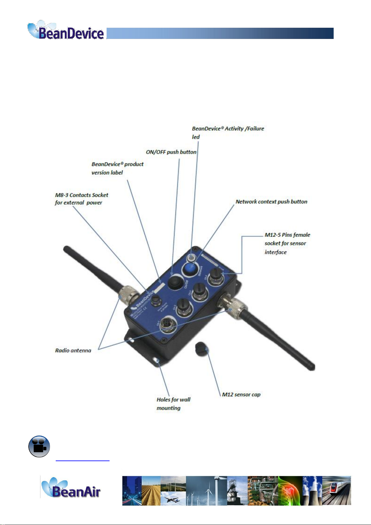
Product focus: Beandevice AN-XX
BeanDevice® AN-XX is a wireless data acquisition system with an embedded datalogger. This product is fully
dedicated to analog sensor with 4-20 mA, Voltage or Low voltage outputs.
Three different models are available: BeanDevice® AN-420 (current loop 4-20 mA), BeanDevice® AN-mV (low voltage
+/- 20 mV), BeanDevice® AN-V (+/-5V and +/-10V).
Beansdevice AN-XX
1

Product focus: Beandevice AN-XX Xtender
2

The BeanGateway® manages and coordinates the wireless sensor network. Its role is to build and oversee the
entire net-work of wireless sensors. It has the ability to identify and verify by authorizing the network access.
It deals with the exchanged data by means of compressing and connecting them to the IP of the network,
thereby reducing the necessary precision in these platforms for maintenance and consequently the
associated cost. The BeanGateway® enclosure comes in two versions: indoor and outdoor.
Indoor Version:
Front view
CNC/ Network push button (Restore
factory settings)
Micro-SD Slot
WSN activity Led
LAN activity Led
ModBus activity Led
2.4GHz antenna
Rear view
5dBi Omni Antenna
Power supply DC 8-28 Volts
OFF (left side)/ON (Right Side) switch
RJ45 shielded & Auto-MDIX socket
for LAN network
RS485/Modbus (Option)
SUBD9/RS232 Connector
Wireless Sensor Networks coordinator (BeanGateway Indoor)
3

Outdoor Version:
Front view
Rear view
4

Power Supply
AC-to-DC power supply for the BeanDevice®
AC/DC adapter 100-240V with M8-3Pins Plug. All region
changeable adaptor provision. (Supplied with the Euro-
pean adaptor as a standard package)
AC-to-DC power supply for the BeanGateway®
100-240V AC/DC adapter with power connector (jack)
To ensure uninterrupted functioning of the BeanGateway, it must be always connected to an external
power source.
5

How to recharge a battery on Beanair product?
AN-XX Beandevice
Beangateway indoor
Jack connector 2,1mm (Int) / 5.1 mm (ext)
1 2
3 : Pwr+
1 : Gnd
2 : Not used
External power supply wiring code
Legend :
Pwr+ : Power supply 8-28V DC
Gnd : Ground
M8 - 3 pins socket
Beangateway outdoor
6
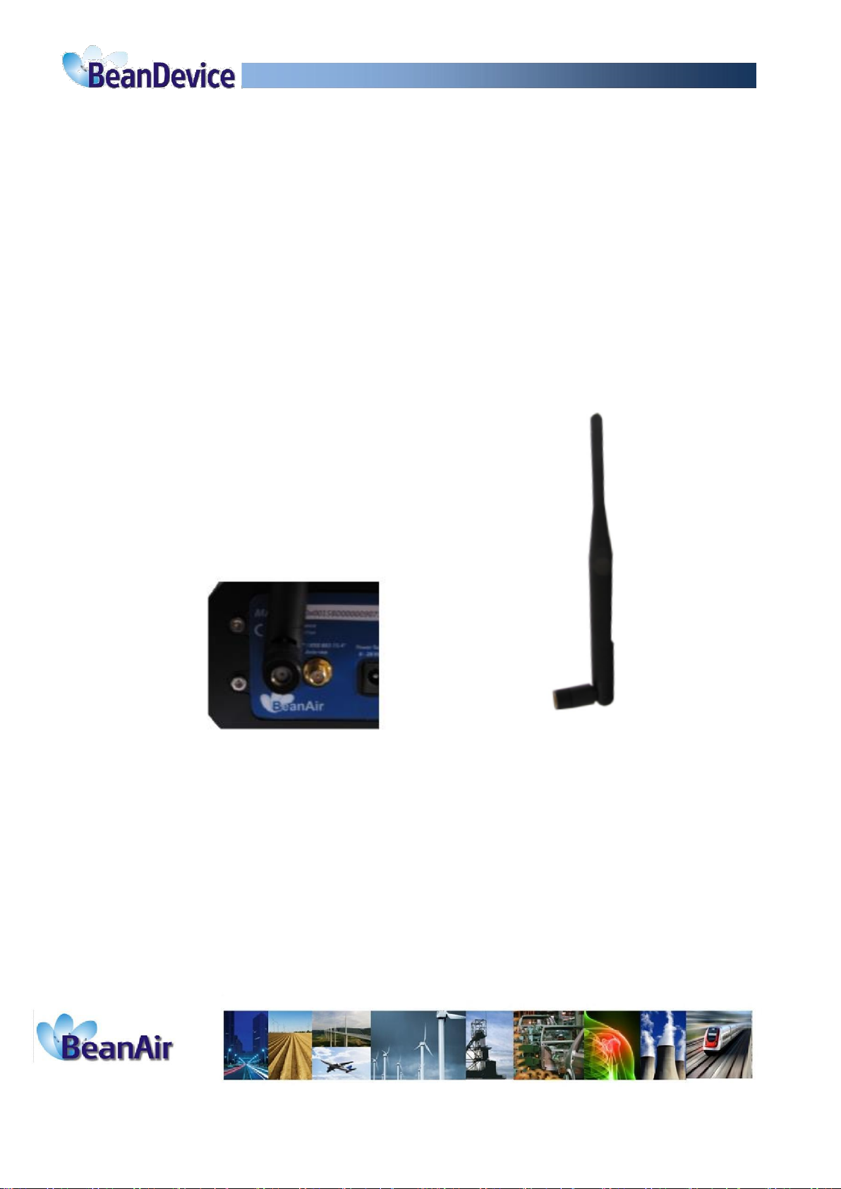
How to plug a Radio Antenna to the BeanGateway®
Be sure that your antenna is compatible with the antenna socket
Screw your antenna on your antenna
Rotate the lock nut until fully tightened
Use only antennas provided by Beanair. You may damage your equipment by using any other antenna.
7
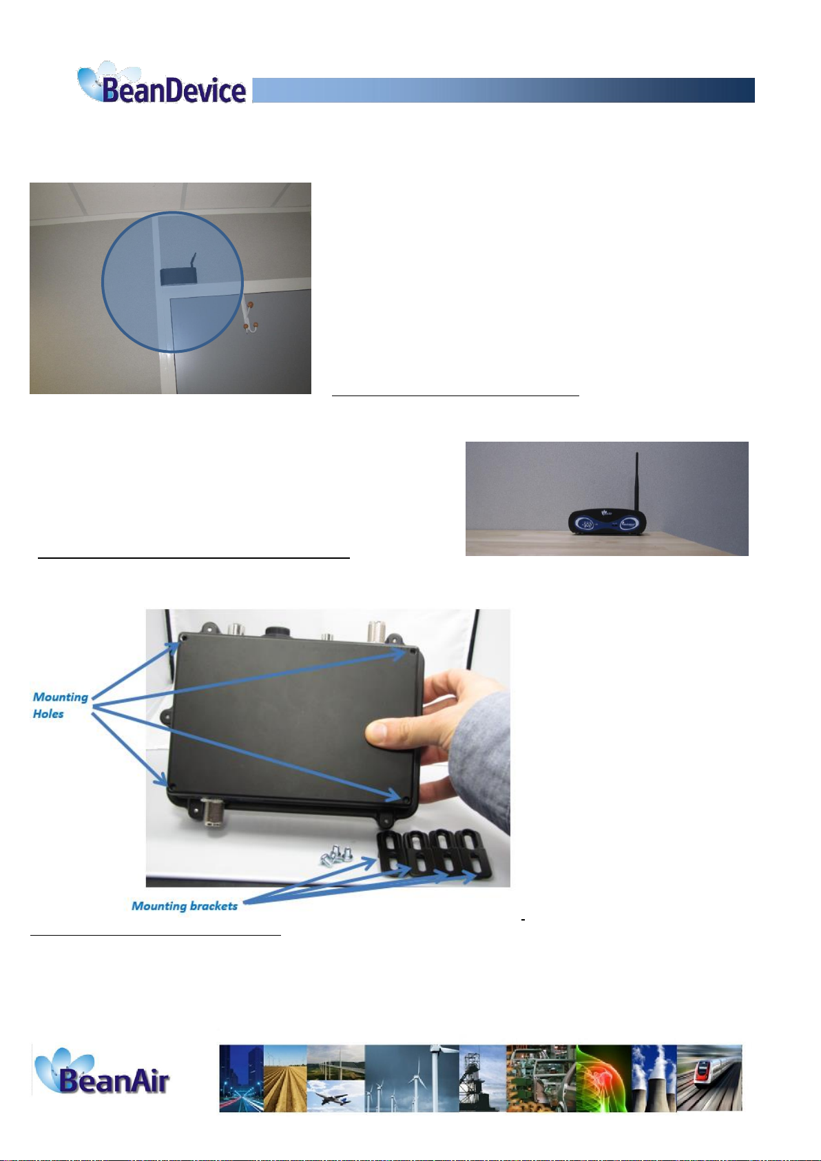
Mechanical Mounting
Wall mounting of Beangateway indoor: If your WSN is deployed
on the same floor, the RF antenna should be mounted vertically.
Desktop Installation of Beangateway outdoor
Wall mounting of Beangateway indoor: The BeanGateway® outdoor is provided with external mounting
brackets (4 x brackets and 4 x M5 attaching screws) enabling the mounting without opening the box.
8

Installation steps
Step1: Turn on the BeanGateway®
Step2: Configure the Beanscape ®on your desktop Computer System (See Beanscape ® User-Manual
click here )
Step3: Connect BeanGateway® Ethernet cable directly to your computer or through a LAN switch.
Step4: Run BeanScape® and double click on the icon
Step5: Click on “Start”to start the server
The Beanscape® launches, and creates a mapping of the BeanGateway® on the bottom of the left side
pane.
Step6: click on the network coordinator, BeanGateway® located in the lower left screen.
The network coordinator will be appointed by the PAN ID.
9
Click «start » button
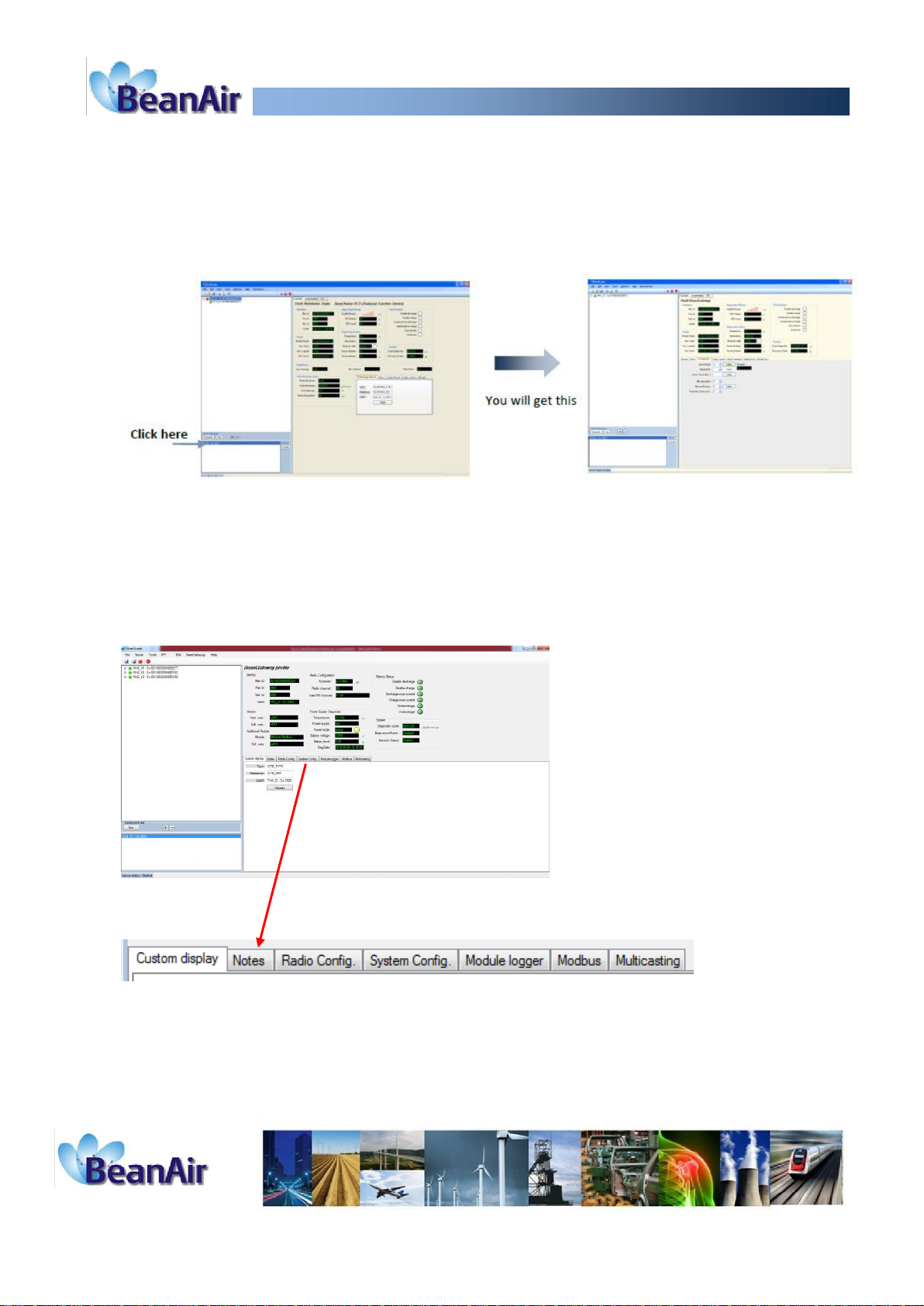
You will see the screen for monitoring and configuring your BeanGateway ®.

Step7: Go to configuration tab in order to choose the best radio channel. .
Channel List: List of channels on which the component can be set. The channels number is 16.
The "0" value is an automatic detection of the most effective channel between channel 11
and channel 26.
To edit this zone, select a value from the list and click the submit button to save.
Step8: Power on the Beandevice: press the ON/OFF push button till the LED flashes in
green.
Watch our video
Processsensor Power On video
Step9: for the first use, perform a Network context deletion operation to restore default
parameters. Press the push button ("Network") for more than 2 seconds.
1

Watch our video
Processsensor Factory settings restoration
Step10: Configure the Beandevice AN-XX
Click here
Step11: connect your sensor to the Beandevice AN-XX
Configure the sensor power supply from the sensor profile (before plugging to the
AN-XX)
Plug your sensor to the Beandevice AN-XX
12
Telefon: +49 (0)6172 5905-45
Fax: +49 (0)6172 77613
E-Mail: beanair@additive-net.de
www.additive-net.de/beanair
This manual suits for next models
7
Popular Conference System manuals by other brands

RADVision
RADVision Scopia XT5000 Series Administrator's guide

Cisco
Cisco 7936 - IP Conference Station VoIP Phone Administration guide

Blaupunkt
Blaupunkt CKT 1 Operating and installation instructions

Crestron
Crestron Mercury CCS-UC-1 Do guide

Vidyo
Vidyo vidyoroom Quick user guide

TERION
TERION UM20-100111B installation manual


