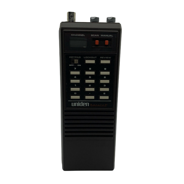
Bearcat 300 User manual

I
LIMITED
WARRANTY
This Bearcats r~ceiveris warranted to the original consumer pur-
chaser to be free fromdefects inmaterialand workmanship for aperiodof
one
(1)
year from the date of purchase as shown on purchaser's receipt.
Electrawill rep?ir or replace, AT ITS OPTION AND FREE OF CHARGE,
during the warranty period,any part which proves defective in material or
workmanship under normal installation, use, and service, provided the
receiver is returned to our factory (address below) or to one of our
authorized Service Centers(listenclosed), TRANSPORTATION CHARGES
PREPAID. Receivers returned to our factory or authorized Service Center
must be accompanied by a copy of purchase receipt. In the absence of
such purchase receipt,
ike
warranty period shall be one
(1)
year from the
date of manufacture as indicated by the seriai number on your unit.
Anjl damage to :his receiver as a result of misuse, abuse, neglect, acci-
dent, improper installation, destruction or alteration of the serial number,
repair or alteration outside our factory or Service Center, or any use
violative of instructions furnished by us WILL VOID THE WARRANTY.
THIS WARRANTY IS LIMITED TO DEFECTIVE PARTS REPAIR AND/OR
REPLACEMENT ONLY AND EXCLUDES ANY INCIDENTAL AND CONSE-
QUENTIAL DAMAGES CONNECTED THEREWITH.
Some states d~ not allow the exclusion or limitation of inciden-
ta! or consequential damages, so the above limitation or exclu-
sion may not apply to you.
This warranty gives you spec~flclegal r~ghts,and you may also have
other r~ghtswh~chvary from state to state
In
the event of a problem wlth
warranty servlce or performance. you may
be
able to gc~to
d
small clalms
court,
a
state court, or a federal d~str~ctcourt
OWNERS
MANUAL
MONITORS
VHF
and
UHF
FM
RADIO SERVICES
Hams
Utility
Services
Special
Emergency
Police
Industry
Disaster
Relief
Government
Business
School
Buses
Forestry
Hospitals Transpoi
tation
Conservation
Ambulances
-r3~irahr.
a
cLAa,,m"-
Mobtle
Telephones
Automobtle
Emergency
,
Raliroads
Press
Mar~ne
Paglng
F~re
Manufacturers
Trucks
Alrcraft

TABLE OF CONTENTS
RadioServices
.....
Front Cover
...........
Table of Contents .1
Technical Specifications
.....
.2
General Description
.........
.3
..........
Safety Precautions .3
........
Safety Instructions .4,5
.......
Operating Instructions .6
Front PanelControls
........
.7
Display Features..
..........
.9
..
Programming Frequencies .10
......
Direct Channel Access
.ll
............
Channel Banks -11
..............
Scanning .11,12
..................
Lockout .12
Speed
.....................
12
Dim
.......................
12
UNDERWRITERS
LABORATORIES
LISTED
.....................
Time .13
...................
Priority .13
..................
Auxiliary .13
.....................
Count 14
.....................
Delay 14
........
ProgrammedSearch .I5
..........
Service Search .16,17
......
Auxiliary Function. .l7,18
ExternalAntenna
..........
.19
..........
ExternalSpeaker. .19
MobileInstallation
......
.19, 20
...........
Useful Hints. .21,22
...................
Service .23
...................
Birdies .23
Frequency Allocations
...
.24-26
...........
Warranty BackCover
Certified in accordance with
FCC Rules and Regulations
Part
15.63
as of date of
manufacture.
CAUTION
TO PREVENT FIRE OR SHOCK
HAZARD, DO NOT EXPOSE THIS
APPLIANCE TO RAIN
OR MOISTURE.
For future reference,write the model number and serial number below. YOU
will find them printed on the back of your radio.
Model No. SerialNo.
Purchasedfrom: Date
I
TECHNICAL SPECIFICATIONS*
I
Size:
12 1h"W
x
4"H x7 1h"D
Weight:
6 Ibs.
Cabinet:
Painted texture steel or vinyl-clad steel
.
Power Requirements:
117Vac, 20W 13.8Vdc, 9W
Antenna:
Telescoping whip (supplied) Connector
provided for external antenna
(50-70ohms)
Clock:
Crystal-controlled,vacuum fluorescent
display of hours, minutes, seconds.
Keyboard-resetable
Frequency Coverage:
Low Band 32-50MHz
Aircraft 118-136MHZ
2-Meter Amateur 144-148MHz
High Band 148-174MHz
70 CM Amateur 421-450MHz
UHF Band 450-470MHz
I
UHF-T Band 470.0125-512.0125MHz
RF Sensitivity:
0.4uV 32-50MHz
0.4uV 144-174MHz
0.8uV 421-512MHZ
(+3KHz deviation 12db SINAD)
I
l.OV for 10db SIN Aircraft 60% mod.
i
I
'
Squelch Sensitivity:
Equal or better than
specified RF sensitivity
j
IF Selectivity:
-60db
@
*
25KHz
ScanlSearch Speed:
Selectable 5 or 15channels per second
!
ScanlSearch Delay:
Selectable 0 or 2 seconds
Audio Output:
2.5 Watts RMS, 8 ohms. 10% THD (max.)
I
Auxiliary Output:
Will switch 500 ma. d.c. (max. sink)
,'
external load
Front Panel Controls:
Volume (onloff)
Squelch (Auto Squelch)
Display
Keyboard
I
Rear Apron Connectors:
13.8Vdc
117Vac
External Antenna
External Speaker
Tape Output
I
I
Auxiliary Control Terminal
11
Ground Terminal
*Specifications are typical and subject to change without notice.

GENERAL DESCRIPTION
SAFETY INSTRUCTIONS
Your Bearcat 300 isa 50-channel,automatic VHFlUHF
FM
and air-
craft AM scanning radio receiver. Its micro-processorcontrol makes
scanning easy. The advanced search feature allows unknown signals
to be captured and monitored, and their frequencies can be manually
stored in memory for later recall. The versatile keyboard will allow
you tocommand a variety of convenient functions: digital display of
frequencies and channel numbers, direct channel access, scan or
manual control, lockout of unwanted channels,priority for important
transmissions,programmable search, service search, selectable speed
control for both scan and search., and even local time..
.
to the
second!
An internal dual power supply allows ll7Vac or 13.8Vdc operation.
Additional features include external antenna jack, external speaker
jack, tape output jack, auxiliary connector, volume and squelch con-
trols, a large, bright display panel, frequency synthesis requiring no
channel crystals, and track-tuning.
SAFETY PRECAUTIONS
Although your Bearcat 300 is listed with Underwriters Laboratories
for complying with standards of safety, a review of common precau-
tions is recommended:
Do not operate this unit if it
is
wet.
Never touch an electrical appliance while standing
in water or on wet ground.
Do not tamper with the internal circuitry.
Do not connect or disconnect the rear-apron power
connector when the line cord is plugged into an
ac receptacle.
If you suspect an electrical problem exists, refer to the warranty in-
structions and returnyour receiver immediately toElectra for inspec-
tion. Use the original packing carton for secure shipment.
Read SAFETY INSTRUCTIONS before operating the radio. Save the
SAFETY INSTRUCTIONS for future reference.
Warnings on the radio and instruction manual arefor your safety. Operating
and use of instructions should be followed to achieve full satisfaction from
your radio.
The radio should be connected only toa power source of the type described in
the instruction manual and as marked on the radio. Power cords should be
routed so that they are not likely to be walked on or
pinched. The ac power cord is provided with a gripper for ease in removal
from the wall outlet. The power cord should be inspected occasionally for
damage.
The radio should be situated so that its location does not interfere with its
proper ventilation,andplaced away from heat sources suchasradiators,heat
registers, and other appliances that produce heat. The radio should be used
only with a cart or stand recommended by the manufacturer. The radio
should be mounted to a wall or ceiling only asrecommended by the manufac-
turer.
The radio should not be operated near water
-
for example, a wet basement,
kitchen sink, or near a swimming pool.
The power cord should be unplugged from the outlet when left unused for a
long period of time. Also remove batteries (if used).
Care should be taken so that objects do not fall and liquids are not
spilled into the radio.
Damage Requiring Service
-
the radio should be serviced by qualified service
personnel when:
A.
The power supply cord or the plug has been damaged; or
B.
Objects have fallen, or liquid has been spilled into the radio; or
C.
The radio has been exposed to rain; or
D.
The radio does not appear to operate normally or exhibits a marked
change in performance; or
E. The radio has been dropped, or the enclosure damaged.
I
Servicing
-
the user should not attempt to service the radio beyond that
described in the operating instructions. All other servicingshould be referred
to qualified service personnel.
Cleaning
-
radios should be cleaned using a damp cloth.

SAFETY INSTRUCTIONS(Cont'd.)
OPERATING INSTRUCTIONS
Outdoor Antenna Grounding
-
Many of the Bearcat radios have provisions
for connection to an outside antenna. An outside antenna should be located
away from power lines. The antenna system must be grounded to provide
protection against voltage surges and built up of staticcharges. Theantenna
system should be installed only by qualified service personnel. Section 810 of
the National Electric Code, ANSIINFPA No. 70-1978provides information
with respect to proper grounding of the mast and supporting structure,
grounding of lead-inwire toanantenna discharge unit, sizeof grounding con-
ductors, location of antenna-discharge unit, connection to grounding elec-
trodes, and requirements for the grounding electrode.
EXAMPLE OFANTENNA GROUNDING AS
PER NATIONAL ELECTRICAL CODE INSTRUCTIONS
h
I
'I
DOWNLEAD OR
LEAD-INWlRE
MAST
I
1
ROUND
1
I
,,
I
GROUND
1
WIRE
GROUND
CLAMPS
ii
SUITABLE GROUNDING
:;
ELECTRODE DRIVEN
:I
.'
8'
INTO THE EARTH
(2.44
METERS)
a
Use No. 10 AWG copper or No.
8
AWG aluminum or No. 17 AWG copper-
clad steelor bronzewire, or larger asground wires for both mast andlead-in.
bSecure lead-in wire from antenna to antenna discharge unit and mast
ground wire to house with stand-off insulators, spaced from
4
feet (1.22
meters) to
6
feet (1.83meters) apart.
Mount antenna discharge unit asclosely aspossible towhere lead-inenters
house.
By reading this section carefully, you can be using your new scanner
within minutes. Follow the sequenceof directions toavoid confusion.
1.
After unpacking the unit from the carton (save the carton for
possible futureuse),check your Bearcat 300 for shipping damage;
if damage has occurred, contact your dealer immediately per the
warranty instructions.
2.
First insert the ac power cord into the connector provided on the
rear apron of your scanner. Plug the cord into a 117Vac outlet
(mobileinstallation will be discussed later).
3.
Insert the threaded end of the telescoping whip antenna (provided)
intothehole on the top of the scanner. Screwitin clockwisefinger-
tight, and extend it fully.
4.
Turn the scanner ON by turning the VOLUME control clockwise
approximately
113
or itsrotation. The volumecontrolisused in the
conventional manner to adjust the sound to a comfortable listen-
ing level.
5.
Rotate the squelch controlfully counter-clockwiseuntil itswitches
intoAUTOMATIC. Thisfactory-setcircuitpermits thereceiver to
automatically turn off, or mute, irritatingbackground noise while
instantly responding to desired signals.
(For very precise manual squelch adjustment, rotate the control
clockwiseuntil you hear the background "hiss"' then turn the con-
trol back until the noise just disappears again. This is the most
sensitive setting for the squelch control.)
Your radio is now in the "first power-on" condition. The status of
various features is as follows:
A
.
Itis scanning atfast speed asindicated by the rolling
display.
B
.
The first bank (channels
1
thru 10)is selected.
C
.
Priority is inactive; Search Limits are cleared.
D
.
The clock started at 0:00:00 and is not set accurately.
An "E" will show in the 6thposition when "TIME" is
-
selected.
NOTE: The above condition will exist any time the radio is
unplugged or power is interrupted. Lockout, Delay,
Aux., and Count areretained in a non-volatile memory
along with programmed frequencies.
You may hear local signals at this time only if the factory test fre
quencies are active in your area.
You will learn how to program your Bearcat.300with local frequen-
cies shortly.

FRONT PANEL CONTROLS
1.
ONlOFFVOLUME: Turns thereceiver ON and OFFand adjusts
the sound level.
2.
SQUELCH: Keeps theradio quiet unless a signal isbeing receiv-
ed and allows the radio to scan or search for a signal.
3.
AUTO SQUELCH: A convenient, fixed squelch setting.
4.
DISPLAY PANEL: Indicates Channel Number, Frequency,
Delay (d),Lockout (L),Scanning action (rollingzeros or L in lock-
ed out channels),Programming Error (Error),Time, Time Error
(E),Priority
(P),
Channel Banks
(')
Aux.
(.).
5. KEYBOARD: Transfers fingertip commands to the Bearcat
Micro-Processor.
PROGRAM KEYS
thru and used toput frequenciesintothe scan-
ner.
enters frequencies into scan channels from keyboard or from
search display.
SCANNING CONTROLS
-
3
five banks (10channel each)are each included or excluded
for a maximum of 50 channels.
starts SCAN of all selected channels.
-1
Singlesteps receiver through all 50channels; stops search
or scan; prepares the radio for any mode of operation.
(
selects SCANor SEARCHrates of
5
or 15channelsDer se
I.
cond.
indicates the number of times the displayed channel has
received a
signal.
FEATURE CONTROLS
I
locks out displayed channel during SCAN only.
selectively activates a 2-seconddelay toreceivea reply
transmission.
-1
samples channel
1
every two seconds and automatical-
ly switchestoany signalon channel
1
regardless of any
other signals.
Fl
displays TIME when radio is ON or OFF (if selected).
PI
selectively activates AUX. OUT on rear panel.
m]
dimslbrightens display.
SEARCH CONTROLS
I]
enters two selected frequencies as upper and lower
limits for programmed search.
starts programmed search operation.
Ve-AirI
selects or deselects the specified service search func-
tion.
@I
selects or deselects Low band for Service Search.
Pa
selects or deselects High band for Service Search.
l-izFl
selects or de-selects UHF band for Service Search.
vl
stops programmed or Service Search operation.
manually increments programmed or Service Search.
-1
continues programmed or Service Search operation.

I
/
DISPLAY FEATURES PROGRAMMING YOUR RECEIVER
The BC300 display consistsof
11
digit spacesor "windows" in which
lighted characters indicate the programming commands of the
keyboard. The display of features selected or deselected is shown
below:
CHANNEL FREQUENCY
IN MEGAHERTZ
I
I
I
I
I
I
1
10 20 30 40 50
1
I
\
DECIMAL AUX.
5
CHANNEL
BANK
INDICATORS
J
I
11
In this example, from left
to
right, the following information is
I
shown:
1
All 5 CHANNEL BANKS are selected as indicated by dots at
I
lower right of spaces 1-5.
I
PRIORITY is ON (Pin 1stspace)
I,
Channel 49 is selected (in2nd and 3rd spaces)
DELAY is selected (in4th space)
LOCKOUT is selected (in 5th space)
i
The FREQUENCY 460.125MHz (6th thru llth spaces) is pro-
grammed into channel 49.
AUX. is selected as indicated by the dot in lower-right of llth
space.
Read this section thoroughly before attempting frequency pro-
gramming.
Now thatyou areaware of someof theflexibility of your Bearcat 300,
you are ready to enter local frequencies.
You can program your receiver to scan 50 different frequencies, one
for each of the 50channels, arranged in 5 groups of 10channelseach.
EXAMPLES
To program
162.550MHz in desired channel(forexample channel 25):
PRESS:.
-1
step to desired channel (25)
PRESS:
READ: 25 162.550
PRESS:
1-1
step to next channel (26)
To program
471.1375MHz in next channel (26):
-
PRESS:
141
171
11]
1111
131
171
151
READ: 26 471.137 (Roundedoff to 6 places)
This manual selection of channels may continue through all fifty
channels, even without all channel banks having been pressed.
If you attempt to program a frequency that is outside the tuning
rangeof thereceiver, "Error" appears on thedisplay, andyou simply
enter a new frequency.
If you make a mistake on one channel
PRESS: then program correct number.
An alternate method is to
PRESS: twice which erases the mistake and returns
to previous channel frequency.

DIRECT (MANUAL) CHANNEL ACCESS
To display any channel
(Example: 37) when Scanning or manual
operation
PRESS:
rn
-1
READ: 37 in 2nd and 3rd spaces along with frequency
and status information.
When a signal is received on a channel (notlocked out)the scanning
will stop and the display will show:
--
the selected banks
--
the channel number being received
--
the frequency being received
To stop scanning
PRESS:
1-1
The "Manual Mode"
may be selected at any time by pressing
-1
.
All of the 50channels may be displayed in sequence by
.
repeated pressing of the
-1
key.
LOCKOUT
You may wish to lock out certain frequencies in any bank and skip
BANKS OF CHANNELS
over them when scanning.
To program Lockout
on a channel (Exam-
ple: 37)first select that channel manually.
The first bank of channels was automatically selected upon "First
Power-on" and was indicated by the dot in lower right of the 1st
space. After programming thefirst 10channels,continueprogramm-
ing by:
PRESS:
1201
Bank Key. A dot appears in the 2nd space.
PRESS:
/]
11
appears as the channel No.
Continue programming channels
11
thru 20.
Repeat above procedure for banks 30, 40 and 50.
Any bank may be de-selected,
or omitted from scanning, by press-
ingthecorrespondingkey. For exampletodeselect thebank contain-
ing channels 41 thru 50:
PRESS:
(501
Bank Key. The dot in space 5 will disappear.
If all banks are deselected, Bank 10is automatically reselected.
SCANNING
PRESS:
PRESS:
(Lockout(
READ: 37
(L)
(lockoutsymbol appears on this channel)
To remove Lockout
PRESS:
Ilocko;i]
The symbol "L" will disappear froin
this
channel.
SPEED
To scan slowly or rapidly
(5
or 15channels per second)
PRESS:
-Speed
To resume fast scan PRESS:
[Speed1
PRESS:
READ: Rolling Zeros in the 10 right-most spaces of the
display.
The Bank Indicator Dot for the bank being scanned
at that instant.
Lockout Symbols (L)(insteadof zeros) represent-
ing the channels being skipped.
To put your receiver in the "Scanning Mode",
adjust the squelch
properly (seePage 4).Then:
DIM
4
To dim display-
PRESS:
To return to brighter display
PRESS:
F]

TIME COUNT
To display
time'from
the 12-hourclock, go tothe Manual Mode first.
Then:
PRESS: The display shows hours, minutes and
seconds. If an "E" appears, power has
been interrupted and the clock should be
reset.
To set the clock
to 9:02:03 when in the TIME mode
PRESS:
101
191
101
121
101
13]
[El
and Read: 9.02.03
NOTE: All six digits must be entered.
You may also scan or search with thetime andchannelnumber being
displayed.
To remove time
from the display: PRESS:
To display time
when the switch is turned
"OFF",
PRESS:
PRIORITY
This selectable featurewill permit you tohear channel
1
any timeitis
active, regardless of any other signals being received at that time.
Put your favorite frequency in channel
1.
Then:
PRESS:
lPriorityl
"P" is displayed
To de-select Priority
PRESS:
-1
again. "P" disappears
AUXILIARY
To selectively control accessories
attached to the Auxiliary ter-
minal on the rear apron, go to the desired channel manually. Then:
To de-select Auxiliary
PRESS: Dot disappears.
See "Auxiliary Function" section on Page 15.
13
To count
the number of times a channel has received a signal (upto
99).go to that channel manually, for example, 34:
I
PRESS:
/I
Channel 34 is displayed
PRESS:
I
Count
I
The count number will show atthe right
end of the display.
To erase count
from memory
PRESS:
-1
The count number is displayed
PRESS: (DecimalPoint),channel and frequency are
displayed
I
PRESS: counter will display 00
To return to manual
without erasing count
DELAY
Your scanner may be programmed to pause for about two seconds
after
a
transmission onany selected channel. Thisisuseful when both
sides of a conversation are transmitted on the same frequency.
To program Delay
on a selected channel
PRESS:
-1
The "d" will be displayed. The channel
will hold for 2 seconds after the signal
ends.
To de-select delay
PRESS:
1-1
The "d" disappears. Scanning will begin
immediately at the end of the signal.
Delay will alsohold for 2 seconds in Search,if sucha delay isdesired.
14

/
j'
11
PROGRAMMED SEARCH
I
I,
SERVICE SEARCH
To search for signals
continuously between two frequencies in the
sameband (example:160.000MHzto 161.000MHz),gotoany desired
channel manually (example37).Then:
PRESS:
rn
READ: 37 160.000 (onelimit is entered)
PRESS:
rn
I=]
READ:
37
161.000(other limit is entered)
To start search
PRESS: The search frequency will be displayed
and incrementing
To stop search
To increment search manually
PRESS: The search frequency will be displayed.
PRESS:
wl
To resume search
on this channel
PRESS:
I]
Search will continue.
To resume search
on another channel without changing search
limits, step to the desired channel and:
PRESS:
[Search]
To enter a frequency, found while searching,
into the channel on
which you are searching:
PRESS:
(El
Then manually go to the next channel you
want to use and PRESS:
-1
NOTE: Any power interruption will cause the programmed search
limits tobe erased. The limits will have tobe reentered. Tur-
ning the radio "OFF" does not interrupt the power to the
Micro-Processor and will not erase the search limits.
NOTE: IF SEARCH or SERVICE SEARCH is used on Channel
1,
subsequent use of PRIORITY can cause change in program
on Channel
1.
This does not occur on any other channel.
The Bearcat 300 is preprogrammed with over 2100 active frequen-
cies in memory. Service Search arranges these in eleven service
categories, in accordance with FCC frequency assignments, for im-
mediate access to any given interest category. The services and fre-
quency bands used are listed below.
BAND
SERVICE
Police
Fire
Marine
Ham
Emergency
Telephone
Government
Forestry Service
Industrial
Transportation
Aircraft
UHF HI VHF LOVHF
X
X
X
X
X
X
X
X
X
X X
X
X X
X X
X
X
X
X X
X
X X X
X
To use Service Search:
Then
press desired service key.
The appropriate LED will light.
The 5th space in the display indicates the frequency bands being
searched.
STH-.
SPACE
NOTE: The Aircraft Band will indicate LO VHF
I

To eliminate Service Search
on UHF, HI VHF, or LO VHF ranges
PRESS:
'
I
UHF~
,w
or
To restore Service Search
on ranges previously eliminated
PRESS:
,
or again.
To stop during service search,
PRESS:
I
Hold
I
To manually advance Service Search,
PRESS:
1
Hold
I
To resume Service Search,
PRESS:
I
~esumel
To entera ServiceSearchfrequency
intoa channel, PRESS
IE]
.
NOTE: Service search mode of operation iscancelledwhen any of the
following keys are pressed
.
,
thru
-
NOTE: Although most active frequencies are in the
11
Service
Search categories, there will be some active frequencies in
many areaswhich arenot included. These may be programm-
ed into the 50 user-programmable channels.
AUXILIARY FUNCTION
When the auxiliary function is activated selectively on a channel,
(PRESS:
Fl
)
a dot will appear atthe lower-right corner. Each
time the scanner detects a signal on this channel, the AUX. terminal
on the rear apron of your Bearcat
300
will provide a closed circuit of
up to
500
milliamperes of current. This will turn on many remote con-
trolled battery-operated cassette recorders without additional ac-
cessories. NOTE: Some recorders may require additional interface
equipment for controlor audio. This should be installed by a qualified
technician.
Audio for the recorder input is provided by: The External-Speaker
jack which will disconnect theinternal speakerfor silent recording; or
the Tape jack which allows the speaker to remain on for audible
monitoring while recording.
One connection of the tape recorder is made in the following manner.
,l.
Turn the radio off and unplug it from the wall receptacle.
2.
Connect the control wires from the cassette recorder "Remote
"
jack to the AUX. and GND. terminals asshown in Fig.
1.
If the
recorder, set to "play", starts with the receiver OFF, the wires
should be reversed. NOTE: Recorder should not be grounded to
radio or other device in any manner.
3. Plug
in
radio, turnit
ON.
Withtherecorderset
to
operate, stepthe
BC-300 to a channel programmed for aux. control
(PRESS:
ml).
Receive a signal (or open the squelch) and
the recorder should be activated.
4.
Connect theTapeoutput of theBC-300tothe"mic" input of the
recorder asshownin Fig.
1.
Toisolate therecorder ground from
the scanner, coupling capacitors should be used in the ground
and center conductors as shown.
Alternate:
Sound may be
recorded by placing the microphone near the receiver speaker if
preferred.
5.
Adjust the BC-300volume control to proper recording level.
To de-activate
the Aux. function
PRESS: again.
Theaux. control terminal will source
9
ma. and sink 500ma. ItisDro-
tected against reverse voltages. The internal circuitry is show; in
Fig.
2.
RECEIVER
Fig.
1
RECORDER HOOK-UP
9v
TERMINAL
~
BOARD
L-
1
A
AUX
%
GND
DARLINGTON IN4002
TRANSISTOR
Fig.
2
INTERNAL AUX. CONTROL CIRCUITRY

EXTERNAL ANTENNA
In some areas, unauthorized mobile police receivers are unlawful; be
sure to check with local authorities before installing your unit.
The telescoping antenna provided with your Bearcat
300
is recom-
mended for most monitoring. For weak-signal reception, or for
electrically-noisylocations, anappropriateexternalantenna designed
for multi-band coverage should be connected to the unit via coaxial
cable.
RG-58U
is recommended for lengths of up to
50
feet. For
longer lengths
RG-8U
is recommended.
Your Bearcat
300
is equipped with an automotive type of external
antenna jack, and a mating plug (supplied)must be used.
An outside antenna needs only to be high enough to clear sur-
rounding obstructions. Above all, STAY AWAY
FROM
POWER
LINES!
You may be killedupon contact of theantenna with a power
line.
EXTERNAL SPEAKER
Although theinternal speakerof the scanner will provide ample room
volume, in someapplications anexternal speaker suchasthe Bearcat
B-45may be desired. Theexternalspeaker should beplugged intothe
rear-apron jack which will cut off the internal scanner speaker.
MOBILE INSTALLATION
II
-
FLAT WASHER, BLACK
I
I
KNOB
-
TOP MOUNTING BRACKET
Your Bearcat
300
may be installed in any vehicle or boat which has a
12-volt,negative-ground electrical system.
1. Assemble the mobile mountingbrackets and attach tothe scan-
ner as shown on page
19.
2.
Select a location under the dash to hold the scanner and mark
thelocation for two mounting holes on
each
of the top brackets.
Drill the four mounting holes using
a
7/64
drill bit.
3.
Remove the brackets from the scanner by removing the two
bolts securing the bottom brackets. Secure the top brackets to
the dash using two
#6
self-tappingscrews (provided)for each
bracket.
4.
Mount the scanner with the two bolts and flat washers through
the bottom brackets.
5.
Tilt the scanner to the desired position and tighten the knobs.
6.
Connect the dc power cable to the insulated terminal on therear
apron of the receiver: attach the other end of the cable to the
"accessory" or "radio" terminal on the vehicle fuse block.
Because the scanner continues to drain batterv current
(about
lh
amp), even after being turned off, the power lead
should be attached to one of the fuse circuits which is dis-
connected by the vehicle ignition switch.
Be sure the radio cabinet is well-grounded to the car metal
through the mounting frame; otherwise, connect a piece of wire
from the ground screw on the rear apron of the radio to the
metal body of the vehicle.
Because power to the scanner is interrupted by turning off the
vehicle ignition switch, your clock will have to be re-set each
time you restore power. It will "power up" scanning fast, no
priority and bank 10 selected.
7.
Connect an appropriate mobile monitor antenna designed for
multi-band coverage to the scanner. If necessary, the
automotiveantenna,extended about 18inches,can be used with
fair results.

USER
HINTS
Your scannerisa versatile instrument. The following operatinghints
will help you use all its features:
1.
Always remember when programming, the key must be
depressed in order to enter the frequency desired.
2.
If you make a mistake
during any programming steps, simply
press and start again. See programming frequencies on
Page
8
for alternate method.
3. When programming, be sure to press each key firmly in the
center-this assures registering each desired number and avoid
errors.
4.
Never turn the radio OFF by pulling the AC cord from the wall
socket. Always turn the ONlOFF volume control OFF first,
then disconnect the line cord when you must move the radio.
5. When frequency-programming VHF high band and UHF, you
may ignore
decimals and final zeros;
they will be entered
automatically. Thus, program 162.550as 16255.Decimals must
be used, however, in low band.
6.
Write
your programmed channels and matching frequencies on
a sheet of paper to avoid the frustration of trying to remember
what was programmed ona particular channel if itisaccidental-
ly erased. If memory islost, itiscorrected simply by reprogram-
ming the desired frequencies.
7.
When very weak signals are being received, their marginal
nature will sometimesallow the search or scan toresume before
the transmission is complete. This may be remedied by advanc-
ing the squelch control manually to slightly below the noise
threshold (itsmost sensitive setting).
8.
During search,
it is likely that some strong signals will lock in
before they areon center-frequency (e.g.weather may be receiv-
ed on 162.545rather thanthe correct frequency 162.550).This is
often detectable by a raspy, distorted voice quality. Simply
press the button to allow it to ste~another incre
I
J
ment, and note an improvement in quality or signal strength.
The actual signal frequency may be read at the higher-quality
(and stronger-sounding) setting. Often, reducing the squelch
sensitivity will minimize early lock-in during search.
9.
This receiver has high noise immunity because of the quieting
squelch system. However,in cases of stronginterfering noise or
signals, it may be desirable toreduce the length of the antenna
to reduce noise pick-up below a critical level. This may be very
effective in medium and strong signal areas.
10. If priority isalready in use, or if you don't wish touse that func-
tion, you may stillprovide preferred scanning tocertain highly-
desirable channels by inserting the
same frequency into
several channels,
so that it is scanned more often.
11.
When moving or shipping the radio, remove the telescoping
antenna to avoid damage to it or to the internal circuit
assemblies.
12.
CHANNEL BANKS:
Because of the large storage capacity (50
channels)of your Bearcat 300, a system of filing has been pro-
vided so that you may selectively activateor deactivate setsof
programmed frequencies in groups of ten. This not only speeds
up scanning time (whenunwanted banks are deactivated),but
permits you to group categories of monitoring. For example,
you may wish to program your scanner with these services:
1-10 Police
11-20 Fire
21-30 Press
31-40 Mobile Telephone
41-50 Marine
Each bank of channels may be randomly inserted or removed
from the scanning sequence atany time merely by pressing the
appropriatebank key. Itis
not
possible toremove all fivebanks,
as the first bank will resume automatically.
A dot will appear in each of the first five display spaces in-
dicating which bank is being scanned.
13.
DELAY:
When the receiver is scanning or searching, it will re
main on one particular frequency or channel as long asa signal
isbeing received. As soon asthesignal goes off theair, the scan
or search resumes. Also, if it is a "Duplex" channel you will
want to scan quickly to the.next channel which you may have
programmed to receive the reply. If a repeater is being
monitored, the signal usually stays on the air long enough for
both sides of the conversation to be heard.
However
many
transmissions are"simplex": Both transmitters areon thesame
channel. By pressing
-1
while thefrequency or channel is
displayed,a two-secondpause will occur afterthe signalgoesoff
the air before the receiver resumes its scan or search function.
This is usually long enough for a replying communication to be
heard.
To deactivate the delay command, press
-1
a second
time while on that channel.

SERVICE FREQUENCY ALLOCATIONS
If your scanner does not seem to be functioning properly:
1.
Refer to operating instructions to confirm that the proper pro-
cedure for operation has been followed.
2. Be sure the radio is plugged into a working ac outlet.
3. Is it turned
ON?
4.
Check that the telescopingantenna is properly installed.
5. If "Error" appears on readout, you have entered an invalid fre
quency
.
6.
While using the single key-press Service Search.
"image" interferencefrom ham repeaters, cab dispatch, mobile
telephone, etc. may stop search. This may be unavoidable in
your area and does not indicate failure of the radio.
7.
If itisthen determinedthat thereceiverrequires servicing,refer
tothewarranty instructions enclosed with yourunit for the pro-
per repair facility.
8.
When preparing the receiver for shipment,
remove the tele-
scoping antenna, and ac power cord.
9.
Pack the unit in its originalpacking carton and include a brief,
concise description of the observed problem you are having
along with your name, address, phone number and a copy of
your purchase receipt.
BIRDIES
All scanners using frequency synthesized circuits generate signals
called "Birdies". Those signals may interfere with the search fre
quencies on your scanner. Slight adjustment of the squelch control
can minimize the interference.Although the BC-300is relatively free
of this problem, some birdies do exist and may vary slightly in dif-
ferent radios.
If during Search the receiver encounters a "birdie", the scan will
most likely stop. In order to resume searching just press the
-1
button.
'he following is a list of strong "birdie" frequencies:
Because of the short-rangenatureof VHF and UHF
FM
communica-
tions, frequencies allocated to services in one geographical location
will not be heard more than 25-50 miles distance (an exception is
"skip", when signalsbounce back toearth from the ionosphere).For
this reason,a separate frequency directorymust be compiled for each
monitoring arei.
Most standard frequency separations and classifications are
regulated in the United States by the FCC.
...
...
Block allocations and even some discrete frequencies covered
by the Bearcat 300 are shown below.
ABBREVIATIONS
Police
.............................
P.D.
State Police
.....................
St. P.D.
FireDepartment.
....................
F.D.
Special Emergency
.............
Sp. Emer.
Highway Maintenance..
.............
Hwy.
Forestry-Conservation
.........
Fors.Cons.
Government..
.....................
Govt.
Local Government.
...............
L. Govt.
BusinessRadio.
....................
Bus.
Manufacturers.
.....................
Mfg.
Broadcast Remote
.................
BCR.
MobileTelephone.
..............
Mob.Tel.
RadioPaging..
....................
Page.
Special Industrial.
................
Sp. Ind.
MotionPicture
...................
Mot. P.
Power Utilities..
..................
Power
Petroleum..
........................
Pet.
Forest Products.
...............
For.Prod.
Railroad
...........................
R.R.
Automobile Emergency
........
Auto Emer.
RedCross
.............................
U.S. Weather Bureau
.............
U.S.W.B.
U.S. Coastal
&
Geodetic Survey
.............
U.S.C.G.S.
NationalParks.
..................
Nat. Pk.
.........................
IndianAffairs..
Bureauof Reclamation
..........
Bur. Recl.
Department of
Agriculture
&
Forestry
........
Agr.
&
For.
LandTransportation.
.............
LandTr.
30-50MHz
Band
30.01
-
30.56
.......................
Gov~.
30.56
.
30.62
.....................
Sp. Ind.
30.66
.
31.24.
..........
Ind.(Pet. For.Cons.
Bus., For.Prod.)
.
..........
31.26 31.98.
.Sp.
Ind., For.Cons.
-
.......................
32.00 33.00 Govt.
-
.........
33.02 33.16. Hwy., Sp. Emer., Bus.
........................
.
33.18 33.38 Pet.
......................
33.42-33.98.. F.D.
34.00
-
35.00..
.....................
Govt.
35.02
-
35.18.
.......................
BUS.
35.22
-
35.66
.............
Mob.Tel.
&
Page
35.70
-
35.73..
.....................
.Bus.
35.74
-
35.98
...............
Sp. Ind.
&
Bus.
36.00
-
37.00.
......................
Govt.
37.02
-
37.44.
...............
P.D.
&
L. Govt.
37.45
-
37.86
......................
Power
37.90
.
37.98.
...........
Hwy.
&
Sp. Emer.
38.00
-
39.00
.......................
Govt.
39.02
-
39.98.
................
P.D., L.Govt.
40.00
-
42.00
.......................
Govt.
42.02
-
42.94
....................
St.
P.D.
42.96 -32.18
...............
Sp. Ind.
&
Bus.
43.22
-
43.68
...............
Mob.Tel. Page
43.70
-
44.60
.................
Trucks, Bus.
44.62
-
45.06.
..........
.St. P.D., For.Cons.
45.08-45.66..
......................
P.D.
45.68
-
46.04
..........
P.D. Hwy., Sp. Emer.
46.04 -46.50..
......................
F.D.
46.52
-
46.58
.....................
L. Govt.
46.60
-
47.00
.......................
Govt.
47.02
-
47.40.
.
.St. Hwy.47.42
...
.RedCross
47.44
-
47.68
............
Sp. Ind., Sp. Emer.
47.70
-
48.54
......................
Power
48.56
-
49.58
...............
For.Prod., Pet.
49.60
-
50.00
.......................
Govt.
146.174MHz
Band
146.000
-
148.000
...................
HAM
148.010
.........................
.MARS
148.15-
...........................
CAP
148.155-148.250..
..................
MIL
148.290
-
150.750..
..................
USN
150.815
-
150.995..
..................
BUS.
...................
151.010-151.130 HWy.
151.145
-
151.475..
.............
For.Cons.
...............
151.505- 151.595.. Sp. lnd.
151.625
-
151.955.
...................
Bus.
151.985
.
152.240
..........
Mob.Tel.(RCC)
152.270
-
152.450
.....................
Taxi
-
...........
152.480 152.840 Mob.Tel. Page
-
..........
152.870 153-020. Sp. Ind.Mot.P.

153.050
-
153.440
...........
Pet., For. Prod.
153.470
-
153.710..
................
Power
153.740
-
154.115..
...............
L.Govt.
154.130
-
154.445..
..................
F.D.
154.450
-
154.600
.......
.Sp. Ind., Pet.,Bus.
154.655
-
155.145..
...
.P.D., L.Govt., St. P.D.
155.160
-
155.400..
.........
Sp. Emer., P.D.
156.045
-
156.240..
.............
Hwy., P.D.
156.275
-
157.425.
.................
Marine
157.456
-
157.500
..............
Auto Emer.
157.530
-
157.710..
.................
.Taxi
157.740
-
158.100..
.........
Mob.Tel., Page
158.130
-
158.460.
....
Power,For. Prod., Pet.
158.490
-
158.700
..........
Mob.Tel.(RCC)
158.730
-
158.970..
...........
P.D., L. Gov~.
158.985- 159.210..
.............
P.D., HWY.
159.225
-
159.465.
..............
For.Cons.
159.510
.
160.200..
...............
.Trucks
160.215
-
161.565..
..................
R.R.
161.600
.
162.000.
.................
Marine
162.026
-
162.175
...............
Bur. Recl.
162.400
........................
U.S.W.B.
162.475
........................
U.S.W.B.
162.550
........................
U.S.W.6
163.125
-..................
.IndianAffairs
163.175
.......................
Bur. Recl.
163.275
........................
U.S.W.B.
163.388- 163.538
....................
MIL
163.825
-
163.975..
......
...
.......
Govt.
164.025
-
164.075..
.............
U.S.C.G.S.
164.175
-
165.188
.......
Bur. Recl., Nat. Pk.,
Govt., Agr.
&
For.
169.300
..........................
F.A.A.
169.450
-
169.725.
..............
.Ind., Data
170.150
.....................
F.D., BC. R.
170.200- 170.220..
.............
U.S.C.G.S.
170.225
-
170.325.
............
Ind., LandTr.
170.425
-
170.575.
..............
For.Cons.
170.975
-
171.250.
.......
Govt. Ind., LandTr.
171.388
-
172.725
.....
Bur. Recl., For.Cons.,
Ind., Dept.Ag
&
For., Govt.
172.775
........................
Nat. Pk.
173.025-
......................
.U.S.W.B.
173.075
......................
U.S.C.G.S.
173.204
-............
.Press Relay, Mot. P.,
Pet., Bur. Recl.
420-512MHz
Band
420.000
-
450.000
...................
HAM
451.050
-
450.950
..............
RemoteBr.
451.000 -451.150..
..................
Util.
451.175
-
451.750.
.........
.For. Prod., Pet.,
Pwr., Tel. Maint.
451.775
-
451.975
...............
Spec. lnd.
452.000
-
452.500
...............
Taxi, Mot.
Carrier, R.R.
452.525
-
452.600.
..............
Autoclub
452.625
-
452.975.
........
.Motor Carr., R.R.
453.000
-
453.975
........
L.
Govt., P.D., F.D.
454.000
-
454.975
454.000
-
454.975.
...............
Mob.
Tel.
455.000
-
455.975
..............
RemoteBr.
456.000
-
458.975
...............
P.D., F.D.,
Ind., LandTr.
459.000
-
459.975
.........
Domestic Public
460.000
-
460.625.
...............
P.D., F.D.
460.650
-
462.175.
...................
Bus.
462.000
-
462.450
....................
Taxi
462.550
-
462.725
....................
C.B.
462.750
-
462.975.
...................
Bus.
463.000-463.175
...................
Med.
463.200
-
464.975.
...................
Bus.
465.000
-
467.500
...............
P.D., F.D.,
Ind., Land.Tr.
467.750
-
467.925.
...................
BUS.
467.5375
-
467.7375
..................
C.B.
467.7375
-
469.975
............
Pub.Safety,
Ind., Land.Tr.
In some large metropolitan areas, 1 or 2
channels of the "TV Band" (470MHz to 512
MHz) are used for communication purposes.
Each T.V. station (channels 14 through 20)
utilizes
6MHz:
470-476 T.V. Channel 14
476-482 T.V. Channel 15
482-488 T.V. Channel 16
488-494 T.V. Channel 17
494-500 T.V. Channel 18
500-506 T.V. Channel 19
506-512 T.V. Channel 20
Where these frequencies are assigned for
communication purposes, in lieu of a T.V.
station, the 6MHz segment is allocated as
shown here for channel 14 (470-476MHz).
470.0125
-
470.2875
.......
DomesticPublic
470.0124
-
470.2875
.......
Domestic Public
(Base,Mob.)
470.3125
-
471.1375
..........
Public Safety
471.1625
-
471.2875.
..............
Reserve
Pool A
471.3125
-
471.4125.
.............
Pwr., Tel.
Maint.
471.4375
-
471.6375
.............
Spec. Ind.
471.6825
-
471.7875.
........
ReservePool B
471.8125
-
472.3375.
.................
Bus.
472.3625
-
472.4375.
.................
Taxi
472.4675
-
472.7875
............
R.R., Motor
Carrier, Auto Emer.
472.8125
-
472.987.
........
.Pet., For. Prod.,
Mfg.
473.0125
-
473.2875
.......
DomesticPublic
473.3125
-
474.1375
..........
Public Safety
......
474.1625
-
474.2875.
....
...
Reserve
Pool A
474.3125
-
474.4125.
.............
Pwr., Tel.
Maint.
474.4375
-
474.6375
.............
Spec. Ind.
(Mobile)
474.6625
-
474.7875.
..............
Reserve
Pool B
474.8125
-
475.3375.
.................
Bus.
475.3625
-
475.4375
..................
Taxi
475.4625
-
475.7875..
..........
R.R., Motor
Carrier, Auto Emer.
475.8125
-
475.9875
....
Pet., For. Prod., Mfg.
The sameallocation pattern isrepeated for
each of theTV channels 14thru 20. Forexam-
ple, is channel 17 is assigned for com-
munications in your area, "Taxi" would be
490.3625 to 490.4375 and 493.4375 (cor-
responding to 472.3625 to 472.4375 and
475.3625 to475.4375 above). Note that inthe
example, we added three TV channels
(18MHz)tothe channel 14 frequencies.
CHANNEL
NUMERICAL LISTING OF
VHF MARINE
RADIOTELEPHONE
CHANNELS
(MHz)
SHIP COAST
156.050 160650
AUTHORIZED
TRAFFIC
Internattonal Only
lnlernatlonal Only
lnlernatlonal Only
lnternatlonal Only
lnlernatlonal Only
INTERSHIP SAFETY
lnternatlonal Only
Cornrnerclal
Cornmerc~al
Comrnerclal.Cornrnerclal Non-Cornrnerc~al
Cornrnerclal
Port Operat~ons.USCG
Canals. Locks. Pllots
Port Operat~ons.USCG
Env~ronmental.
Hydrographic
DISTRESS. SAFETY,
&
CALLING
Restr~cted.State Control
lnternatlonal Only
Cornrnerclal
lnternatlonal Only
Comrnerc~al
Port Operatlons
lnternatlonal Only
Reslrtcled. USCG
lnlernatlonal Only
Restr~cted.USCG
internat~onalOnly
Restrlcled. USCG
Publ~cCorrespondence
Publlc Correspondence
Publ~cCorrespondence
Publ~cCorrespondence
Publ~cCorrespondence
lnternatlonal Only
lnternatlonal Only
Internattonal Only
Internatlonal Only
lnternatlonal Only
lnlernatlonal Only
lnternatlonal Only
Port Operatlons
lnternatlonal Onlv
156.325 156325 Port Operatlons
156375
Commercial
156425 156 425 Non Comrnerclal
156475 156.475 Non Comrnerclal
156525
--
Non Comrnerclal
156575 156 575 Non Comrnerclal
156.625 Non
Commercial
156.675 156.675 Port Ooeratlons
156725 156725 Port
Operations
-
GUARD CHANNEL. Unuseable
-
GUARD CHANNEL. Unuseable
156875
Commercial
156925 161525 lnternatlonal Only
156925 156925 Non
Commercial
156975 161575
International
Onlv
156.975 156.975 Cornmerclal
157.025 161.625 lnternatlonal Only
157025 157.025
Commercial
157.075 161.675 lnlernatlonal Only
157.125 161.725 lnlernatlonal Only
157.175 161.775 lnternatlonal Only
157.175 157.175 USCG Auxlllary Only
157.225 161.825 Publ~cCorrespondence
157.275 161.875 Public Correspondence
157.325 161.925 Publlc Correspondence
157.375 161.975 Public Correspondence
157.425 182.025 International Only
157475 157.475 Commerc~al
AIRCRAFT
FREQUENCIES
118.00 to 128.8 Air Traffic Control.
at
the
field and up to 30 miles from
malor airports and
-.
includes:
Approach Control
Deoarture Co..trol
Tower
IATISI Automet~e Termlnal
information
Serv,ee
............
Clearance Delivery
lmslorlty of communications
below 125 001
SPECIFIC
FREQUENCIESWITHIN THE 118-135.975
RANGE:
1215 National Alrcraft Emergency
1216 to 121 9 Ground Control of alrcraft at
rnalor
airports
General avlation
aeronautical
advisory stations and Alr
Traffic
Control. Commonly
called Fl~ohtServlce Station
NOTE: Authorlzallon and channels
used
may vary with IOCalll~.Check with local authorities for verification.
26'
(FSS)
Weather Advlsory
FSS at alrport with a tower
Unlcorn-Communications
at
General Aviatlon airports
Alr to Air Commun~cations
Search and Rescue
Fllght test.-manufactureis,
'
elc.
Fl~ght
schools-instruction
Mllltary Towers
Aeronautical
Enroule Fre-
quencles
Alrllnes commun~cattonwith
thew companies
Air Traffic Control beyond 30
mllesof major airport. Usuai-
ly remote stations.
Table of contents
Other Bearcat Scanner manuals
