Beast Tek Transmuter User manual

TRANSMUTER
USER MANUAL
VERSION 1.0


CV/Trigger Inputs to MIDI OUT
Transmuter has eight CV/trigger inputs which are converted into MIDI messages and
sent via the MIDI OUT TRS output.
Inputs 1 to 6 are analog and can detect and transform CV between 0-5v. Input
voltages below 0v will be clipped to 0v and voltages above 5v will be clipped to 5v.
Analog inputs can be used for velocity sensitive NOTE ON messages , Continuous
Controller messages, After Touch messages etc.
Trigger signals can for example be run through a VCA before connection to
Transmuter to allow the trigger signal/level to be modifed and affect the velocity of
the MIDI notes generated. This allows the introduction of dynamics which can
greatly enhance musicallity.
The analog inputs can also function as digital inputs (Program Change, Clock,
Transport etc) if CV functionality is not required.
Inputs 7 & 8 are digital and can only send Note On, Program Change, Clock and
Transport messages.
MIDI IN to CV/Trigger Outputs
Transmuter has eight CV/trigger outputs which are controlled from MIDI messages
supplied to the MIDI IN TRS input.
Outputs 1 and 2 have an accompanying CV output and can be used to convert MIDI
note velocity, continuous controller (Pitchbend, Mod Wheel etc), Aftertouch etc into
a CV signal between 0 and 5v.
Oututs 3 to 8 are digital only and can only be used for trigger/gate signal generation
for MIDI Note On, Clock and Transport (Start/Stop/Continue) messages.
Outputs can be set to Gate or Trigger with configurable pulse length (1ms, 2ms, 5ms,
10ms or 50ms).

Jumper Settings / Cable Selection
The Beast-Tek cables supplied with the kit are MIDI TRS Type A cables. Type A is the MIDI standard. Some manufacturers
use the opposite wiring which is known as type B. Transmuter can be configured to operate with either Type A or Type B
by configuration jumpers on the back. The following jumper settings are looking at the back of the module, with the
module upright:
Type A The Beast-Tek MIDI TRS cables are type A. Use this setting for the cables supplied with Transmuter.
Type B is for interoperability with cables from other manufacturers. This setting will not work with the supplied cables.
The following jumper settings are invalid and will not work:

Basic Operation (Preset selection and MIDI learn without PC)
The Load/Learn button allows basic programming of transmuter without a PC. MIDI Learn mode without a PC will map a
note or CC (I/O 1 & 2 only) to both the MIDI to trigger output and the MIDI to trigger input.
This can be handy for setting up Drum Machines, Samplers and Controllers. For more complex configurations the PC
application must be used.
The single Load/Learn button on the front panel responds to different length presses. The button must be pressed down
and held for a certain duration.
Short Press – Less than 0.9 seconds (or 900 msec)
Medium Press – More than 0.9 seconds and less than 3.5 seconds (900 - 3500 msec)
Long Press – More than 5 seconds (5000 msec +)
Loading a Preset
A medium press of the load/learn button will enter preset load mode. When preset load mode is entered, LEDs 1 through
8 will flash sequentially then LEDs 8 through 1 sequentially to indicate preset load mode has been selected. Once the brief
flashing sequence has completed the LED of the current preset will remain illuminated. For example: if preset 5 is active,
then LED 5 will be illuminated.
A short press can now be used to cycle between the eight presets., with the LED of the selected preset number being
illuminated. Once the desired preset has been selected, a medium press will load the selected preset. The selected preset
LED will flash quickly for approx 1 second and then load.
If preset load mode has been selected by accident, a long press will cancel. The the of the previously loaded preset will
flash quickly for approx 1 second and then preset load mode will be cancelled.

Midi Learn (and saving to a preset)
A long press of the load/learn button will enter MIDI learn mode. LEDs 1 through 8 will flash sequentially twice to indicate
MIDI learn mode has been entered.
MIDI Learn mode will listen for Note On, Note Off and CC messages on any channel. Note: CC messages are available on 1
and 2 as these are the only I/O groups with CV outputs. CC messages on 3-8 will be ignored.
Gate Signals: If a MIDI Note On and Note Off message is received then this note will be learned as a GATE signal.
Eg. MIDI to trigger output will be HIGH until a note off message is received
Trigger Signals: If a MIDI Note On is received and another MIDI Note On is received before a Note Off message, then it will
be learned as a TRIGGER signal with a 5ms pulse width.
Once a note/cc has been learned, the LED for that I/O will illuminate to indicate it has been learned.
This process repeats until all 8 I/Os have been learned/mapped. All 8 LEDs are illuminated and flash rapidly for 1 second to
indicate the learn process has been completed. The learned configuration must now be saved into one of the 8 preset slots
available. LED 1 is illuminated to indicate that preset slot 1 is selected. Use short presses of the load/learn button to cycle
between preset slots. Once the desired preset slot is chosen, perform a medium press of the load/learn button to save this
configuration into that preset slot. The LED of the selected LED will flash quickly during the save process and when the LED
stops flashing, the preset is active and ready for use.
Alternatively, if there was a mistake made during learn process. A long press of the load/learn button during the selection
of the preset save slot will abort the learn process and re-load the last active preset.

Factory Presets
1. Behringer RD8
Preset 1 is configured for MIDI IN/OUT with the Behringer RD8 set to MIDI Channel 10. The sequencer can be used to
generate eurorack trigger signals via MIDI IN and eurorack triggers can trigger sounds on the RD8 via MIDI OUT.
2. Arturia Drumbrute
Preset 1 is configured for MIDI IN/OUT with the Arturia Drumbute set to MIDI Channel 10. The sequencer can be used to
generate eurorack trigger signals via MIDI IN and eurorack triggers can trigger sounds on the Drumbrute via MIDI OUT.

3. Transport + Clock / SP404SX
MIDI IN -> TRIG/CV OUT MIDI Input is configued to allow a MIDI sequencer to sync with eurorack sequencers/modules.
OUT1 & OUT2 are configured for Volume and Pan MIDI CC messages on Channel 10. Volume and Pan CC messages will set
the CVs on CV OUT 1 and CV OUT2 between 0v and 5v.
OUT3 is a gate signal that goes high when START is pressed and will stay high until stop is pressed. OUT4 is configured as
the inverse of OUT3.
OUT5 through OUT8 are different divisions of the MIDI clock 24, 16 and 1TPQN.
TRIG IN -> MIDI OUT Preset 3 Is configured for eurorack triggers to trigger sounds on a Roland SP404SX via MIDI OUT.
4. Transport + Clock / MIDI Drum
MIDI IN -> TRIG/CV OUT MIDI Input is configued to allow a MIDI sequencer to sync with eurorack sequencers/modules.
OUT1 & OUT2 are configured for Volume and Pan MIDI CC messages on Channel 10. Volume and Pan CC messages will set
the CVs on CV OUT 1 and CV OUT2 between 0v and 5v.
OUT3 is a gate signal that goes high when START is pressed and will stay high until stop is pressed. OUT4 is configured as
the inverse of OUT3.
OUT5 through OUT8 are different divisions of the MIDI clock 24, 16 and 1TPQN.
TRIG IN -> MIDI OUT Preset 3 Is configured for eurorack triggers to trigger sounds on most generic drum machines via
MIDI OUT.

5. Transport + Clock / Elektron Model Samples/Cycles
TODO cycles/volca drum / sAMPLES
MIDI IN -> TRIG/CV OUT MIDI Input is configued to allow a MIDI sequencer to sync with eurorack sequencers/modules.
OUT1 & OUT2 are configured for Volume and Pan MIDI CC messages on Channel 10. Volume and Pan CC messages will set
the CVs on CV OUT 1 and CV OUT2 between 0v and 5v.
OUT3 is a gate signal that goes high when START is pressed and will stay high until stop is pressed. OUT4 is configured as
the inverse of OUT3.
OUT5 through OUT8 are different divisions of the MIDI clock 24, 16 and 1TPQN.
TRIG IN -> MIDI OUT is configured so that the Elektron sequencer can be controlled and sounds triggered from eurorack.
6. Elektron Model Samples/Cycles
MIDI IN -> TRIG/CV OUT is configured so that the Elektron sequencer can generate eurorack triggers and clock/reset to
drive eurorack modules and sequencers.
TRIG IN -> MIDI OUT is configured so that the Elektron sequencer can be controlled and sounds triggered from eurorack.
7. NAVA
MIDI IN -> TRIG/CV OUT MIDI Input is configured to convert MIDI Note On messages generated by Nava into eurorack
triggers.
TRIG IN -> MIDI OUT MIDI Output is configured to convert eurorack triggers to control drum voices on Nava.
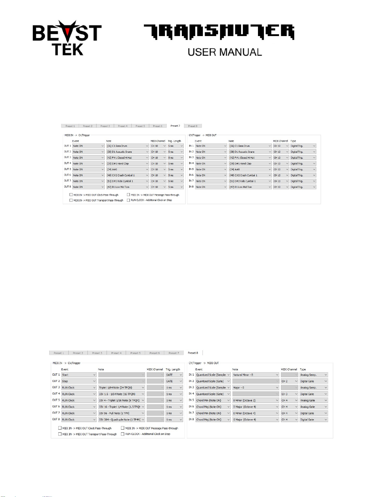
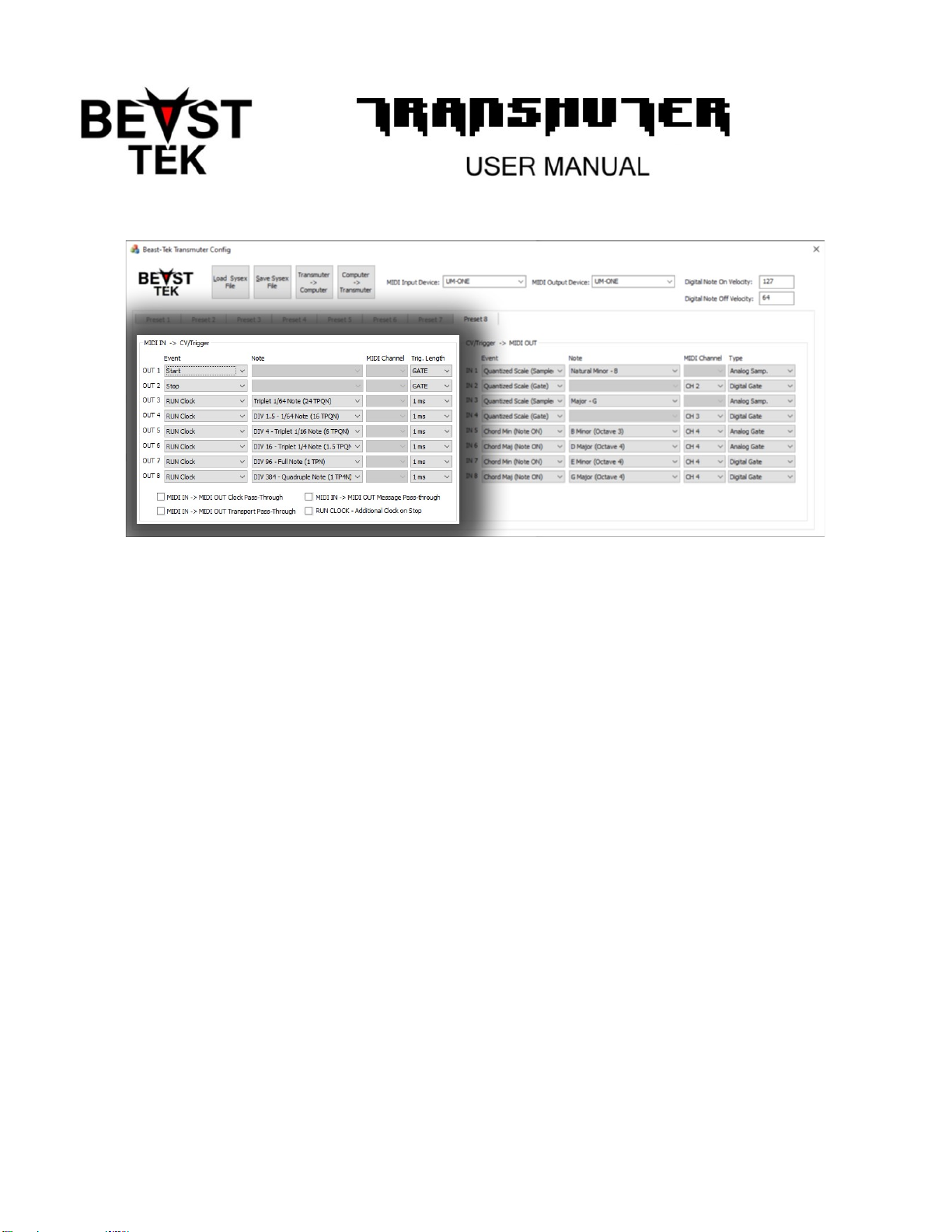
8. Transport + Clock / Quantized Scaled and Chords
MIDI IN -> TRIG/CV OUT
MIDI Input is configued to allow a MIDI sequencer to sync with eurorack sequencers/modules. OUT1 is a gate signal that
goes high when START is pressed and will stay high until stop is pressed. OUT2 is configured as the inverse of OUT1.
OUT3 through OUT8 are different divisions of the MIDI clock 24, 16, 6, 1.5, 1TPQN and 1 TP4N.
TRIG IN -> MIDI OUT
IN1 + IN2 are set to sampled quantized scale on the B Natural minor scale.
IN3 + IN4 are set to sampled quantized scale on the G Major scale.
IN5 through IN8 are mapped to B Minor, D Major, E minor and G major chords.
Transmuter Configuration Utility
The Transmuter Configuration Utility is a 32 bit Windows application. It has been tested on Windows 10 but may run on
older versions (if you are lucky).
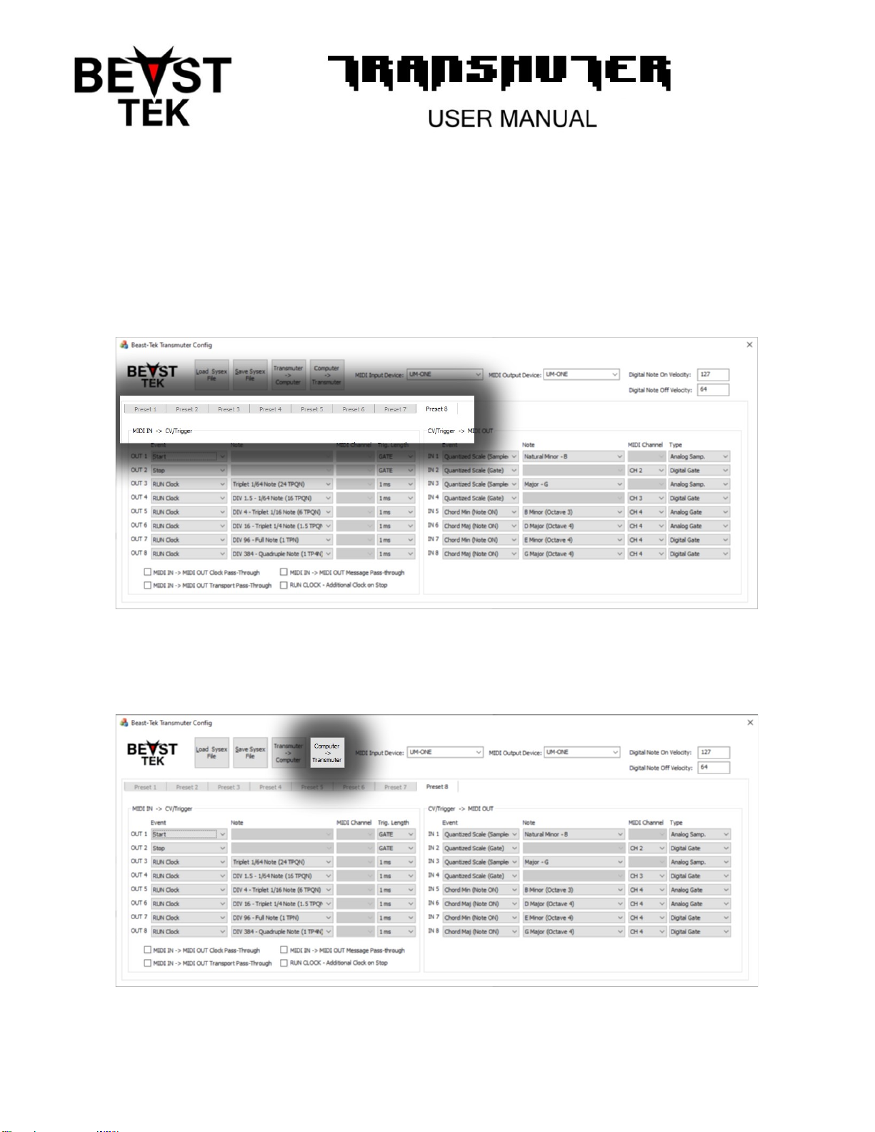
The Transmuter has 8 presets, each with its own set of configuration or “mappings”. The Tab control allows navigation
between each of these mappings.
When the Transmuter Configuration Utility starts, factory default presets are loaded.
Using the button labled “Computer -> Transmuter” all 8 presets from inside the configuration utility will be
transferred/written into the Transmuter Module.
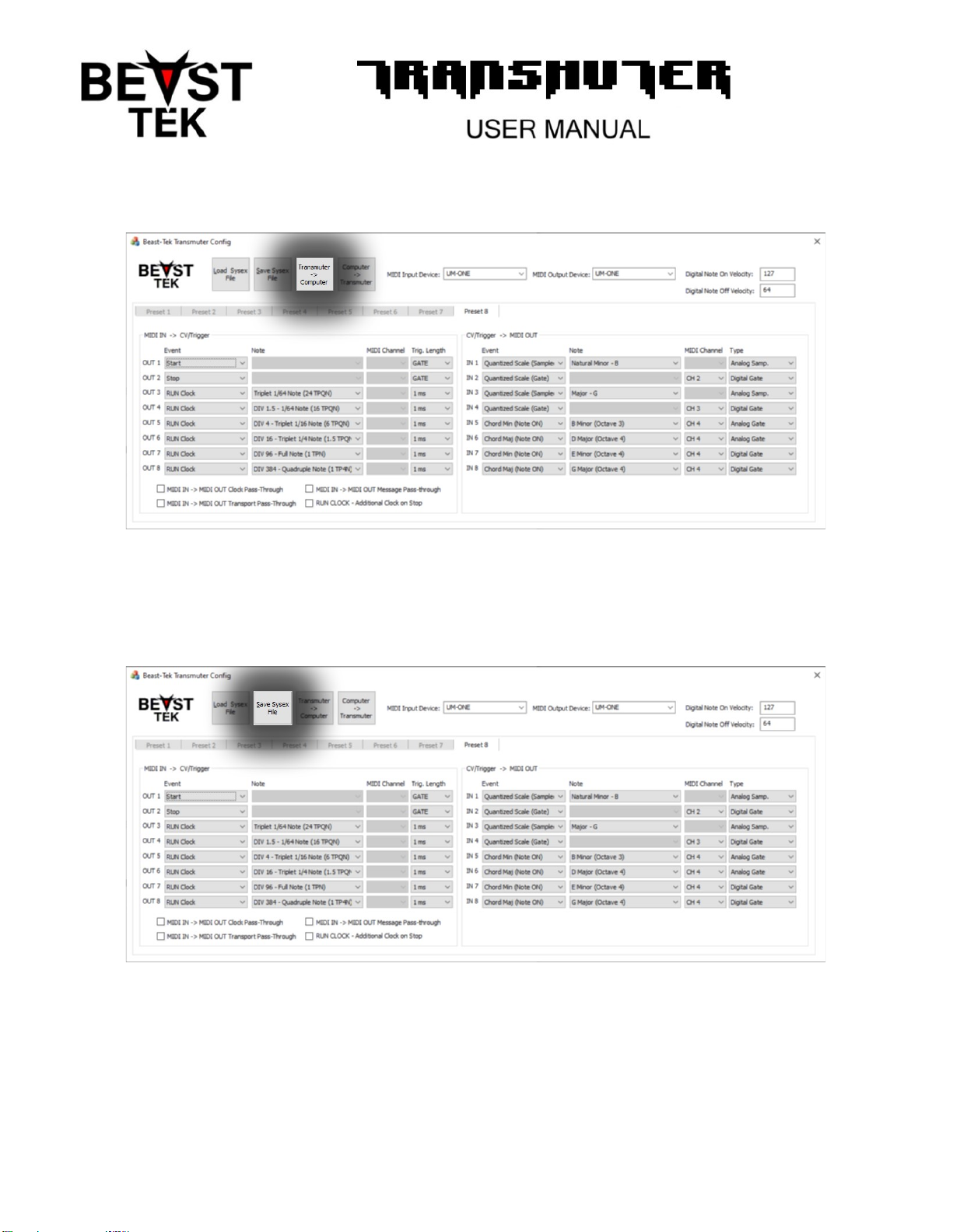
Using the button labled “Transmuter -> Computer” all 8 presets from inside the Transmuter module will be
transferred/read into the configuration utility for viewing/editing.
Using the button labled “Save Sysex File” will save all 8 presets into a .syx Sysex file that can be used as a backup,
transferring presets to other people or programming the Transmuter module with other MIDI utilities that support syx
files.
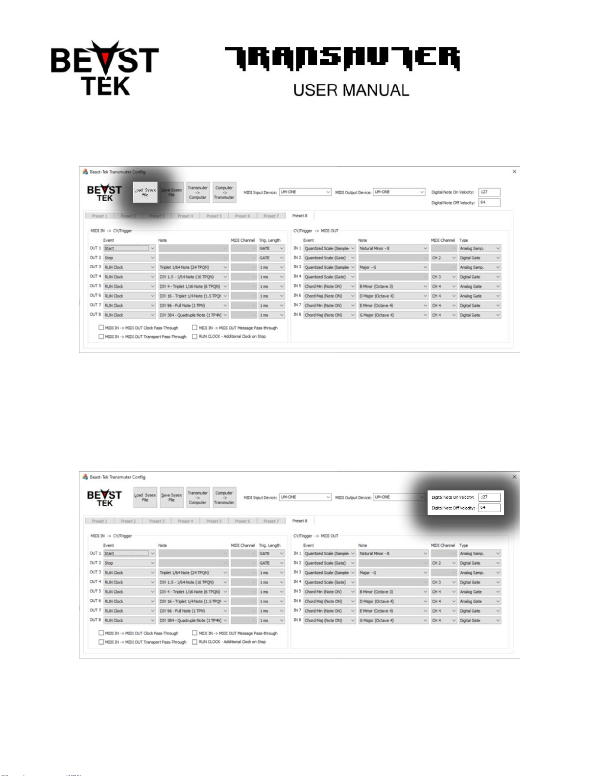
Using the button labled “Load Sysex File” will load all 8 presets from a .syx Sysex file into the Transmuter Configuration
Utility for viewing/editing/transfer.
MIDI Note On and Note Off messages have a velocity which represents how hard/quickly the key was pressed or released.
Digital triggers are simply on or off and have no concept of velocity. The Digital Note On Velocity and Digital Note Off
Velocity options specify the Velocity values that are used across all 8 presets for Digital triggers. Valid vaues are 0 – 127.
Note: a Note On with a Velocity of 0 is typically equivalent to a Note Off message.

Transmuter Configuration Utility – MIDI Connection
Transfer between the Transmuter Configutation Utility and the transmuter Module occurs via MIDI. This means a
computer MIDI interface (such as the Roland UM-1) is required.
The MIDI output from the computer is connected to the MIDI IN on transmuter and the MIDI input on the computer is
connected to the MIDI output on the Transmuter module.
The correct MIDI Input Device and MIDI Output Device need to be set inside the Transmuter Config Utility, they should
both match the MIDI interface that you are using to connect with the Transmuter Module.
MIDI IN to CV/Trigger Outputs (TRIG OUT)
Background
Eurorack is the wild west as far as transport (start/stop/reset/run) and clocking is concerned. Because there is no standard
for this, every possible combination has been implemented across many, many different modules.
MIDI Sequencers can also be vastly different. MIDI provides START, STOP, CONTINUE and Song Position Pointer messages.
Some MIDI sequencers implement only START and STOP. Others Implement START, STOP and CONTINUE where the STOP
also performs a RESET. Others have a reset function via a button that looks like a rewind button. Sometimes STOP will
reset the sequencer to the start of the song/pattern.
This inconsistency is frustrating and its for this reason that Transmuter provides the ability to configure the MIDI transport
and clock messages into just about all of the possible combinations to allow eurorack sequencers and other modules to
sync perfectly with MIDI gear.
Whilst MIDI has a clock resolution of 24 TPQN, many eurorack modules have a different colck resolution, often 8, 4, 2 or 1
TPQN. For this reason, Transmuter has a built in clock divider which can divide the MIDI clock down to the required clock
resolution.

Digital Events – TRIG OUTS 1 through 8
Transmuter has eight Trig Outputs, Two of which are analog capable and the remaining six which are digital (trigger or
GATE only). The two analog Outputs can also function as digital outputs if desired.
Note On
Probably the most common use of the transmuter is converting MIDI Note On messages from sequencers or drum
machines into eurorack gate and trigger (aka pulse) signals. This is to enable MIDI sequencers/controllers to trigger
drum/sampler modules and any other function that takes a trigger such as an ADSR/function generator etc.
Each of the 8 transmuter outputs can be mapped to one specific MIDI note on any of the 16 MIDI channels.
MIDI Clock
The MIDI clock is always running. MIDI devices utilize START, STOP and CONTINUE along with SONG POSITION POINTER
(SPP) messages to control sequencing and position within the sequence/song.
Some (mostly digital microcontroller based) modules can accept a 24 TPQN midi clock signal in conjunction with a RUN
signal. Some modules expect an active high RUN signal and some expect an active low RUN signal. The required RUN signal
can be generate by Transmuter with a either a START or STOP message configured as a GATE.
The diagram below illustrates MIDI clock along with PLAY as gate signal that goes high when MIDI Start is received and
stays high until MIDI Stop is received. The diagram also illustrates a MIDI sequencer that performs reset by sending a
SongPosition Pointer 0 message (on the 6th step).
Start and Stop
MIDI sequencers send a START message when a song or parttern has been activated, often by the pressing of a PLAY
button. Transmuter can be configured to turn the START message into a trigger with a pulse length between 1 ms and
50ms OR a GATE signal that will stay active/high until a STOP message in encountered.
Conversley Transmuter can be configred to turn the STOP message into a trigger with aa pulse legth between 1 ms and 50
ms OR a GATE signal that will stay active/high while the sequencer is not playing.

RUN Clock
Many eurorack sequencers and modules are build with discrete logic chips (without microcontrollers or onboard
computers) and expect the clock to be active while the song is playing. The RUN clock input is a combination of MIDI Clock
and START/STOP messages. RUN Clock only produces clock pulses following a MIDI START message and continues to
produce clock messages until a MIDI STOP message is received.
This sounds simple enough, however some sequencers require a clock pulse following a ‘RESET’ to move back to the first
step of the sequence (sometimes called “Clock on first”). Others immediatley move to the first step following a ‘RESET’ and
the transmission of the first clock would cause the sequencer to move to the second step (sometimes called “Clock on
last”).
Transmuter RUN Clock implements “Clock on first”, generating the first clock pulse to transition back to the first step
following a reset.
SKIP Clock
Transmuter SKIP Clock implementes “Clock on last”, blocking the first clock pulse for sequencers that immediatley
transition to the first step following a ‘RESET’. See “RUN Clock” section for more explanation on this topic.
Reset SPP, Reset (SPP + START) and Reset (SPP + STOP)
MIDI has START, STOP, CONTINUE and Song Position Pointer transport messages for communication and synchronization
with other MIDI gear. Unfortunately not all MIDI equipment implements all of the messages and often CONTINUE or SPP is
overlooked. As mentioned in previous sections, different eurorack sequencers require different transport signals.
For there reasons, Transmuter provides 3 options for Reset messages.
Reset SPP – will generate a trigger or GATE signal when a Song Position Pointer (SPP) with a value of 0 is received.
Reset SPP + START – will generate a trigger or GATE signal when a Song Position Pointer (SPP) with a value of 0 OR when a
MIDI Start message is received.
Reset SPP + STOP – will generate a trigger or GATE signal when a Song Position Pointer (SPP) with a value of 0 OR a MIDI
Stop message is received.
Additionally you can utilize Start and Stop messages as trigger/gates for use as reset signals depending on the MIDI device
and the eurorack modules being used.
Event
Note
MIDI Channel
Trig. Length
Note On
Selects the MIDI Note that will generate a
trigger/pulse on the selected OUT jack.
Selects the MIDI
Channel (1-16)
for the Note On
message.
Sets the length/width of
the pulse (aka Trigger)
that is generated when
the selected MIDI event
occurs.
Pulse/Trigger length can
be 1, 2, 5, 10 or 50
milliseconds.
A GATE option is also
available that can be
used for Note On so that
the Trig Out stays high
until a Note Off message
is received.
The GATE option can
also be used with Start
and Stop messages.
Start
N/A
N/A
Stop
Reset (SPP)
Reset (SPP + STOP)
Reset (SPP +START)
MIDI Clock
MIDI clock is 24 ticks (aka pulses) per quarter
note.
Transmuter can divide this clock down by 1.5, 2, 3, 4,
6, 8, 9, 12, 16, 18, 24, 36, 48, 72, 96, 192 or 384 to
produce different clock rates either for compatibility
with different sequencers, syncing LFO’s or even
triggering kicks or hats etc.
N/A
RUN Clock
SKIP Clock

Clock and Transport - Putting It All Together …
Unfortunatley the answer here is that you need to know your sequencer(s). Manuals often have MIDI implementation
charts and some module manuals explain the clocking nuances. Others don’t.
MIDI utilities such as MIDI OX allow you to see the MIDI messages generated by your MIDI gear and numerous oscilloscope
modules allow you to visualize the clock and reset signals for your eurorack sequencer.
By far the most compatible approach is to give up altogether on “CONTINUE” and focus only on Start and Stop – where
stop is also a “Reset back to the beginning of the song” message.
You will need to know what clock resolution in TPQN your eurorack sequencer takes and use Transmuter to divide the
MIDI clock down to the appropriate division.
Analog Events ( TRIG OUTS 1 – 2 and CV OUT 1 – 2 )
Transmuter has two CV outputs that are couled with the two corresponding TRIG OUTs.
TRIG OUT 1 and CV OUT 1 act as a pair named “OUT 1” inside the Transmuter Config Utility.
TRIG OUT 2 and CV OUT 2 also act as a pair named “OUT 2” inside the Transmuter Config Utility.
This means OUT 1 and OUT 2 are capable of generating analog CV signals in addition to digital trigger/gate signals.
Note On
Note On messages on OUT 1 and OUT 2 will also convert the Velocity of the midi note into a CV signal between 0v and 5v.
Velocity 0 = 0v CV and Velocity 127 = 5v CV. This CV can be utilized to add dynamics into your music, for example hihats or
claps can be “animated” using a VCA following the drum module/sampler output or using the ACCENT input (if your drum
module has one).
Pitch Wheel, AfterTouch and Channel Pressure
Pitch Wheel, After Touch and Channel Pressure messages can be configured on OUT 1 and OUT 2, converting the Pitch
message into a CV signal between 0v and 5v.
Control Change
Control Change or Continuous Controller (often reffered to as CC) messages exist in many different forms on sequencers
and MIDI controllers, for Volume, Cutoff, Modulation and many other numerous purposes.
OUT 1 and OUT 2 can be mapped to any MIDI CC message and generate a CV between 0v and 5v.
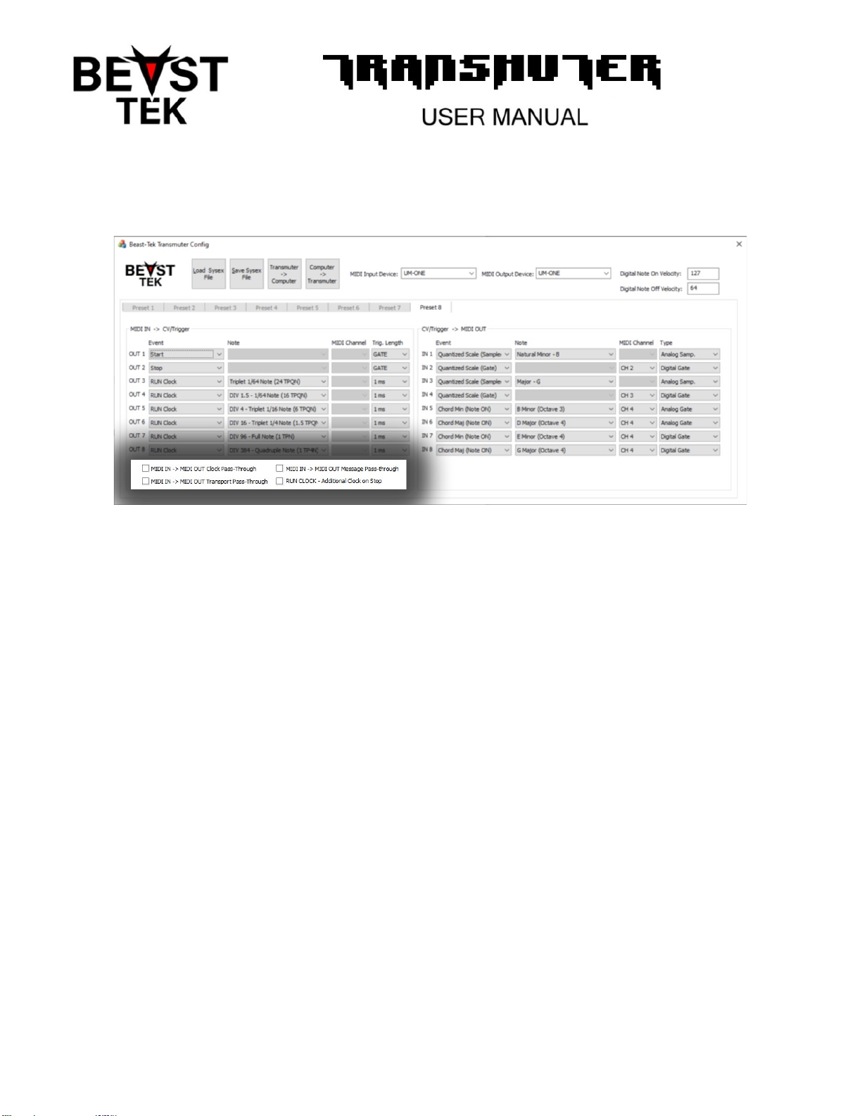
Additional Per-Preset Options
MIDI IN -> MIDI OUT Clock Pass-Through
Enabling this option will cause MIDI clock messages received on MIDI IN to be output on the Transmuter MIDI OUT. This
can be useful if you have a Master MIDI sequencer connected to the Transmuter MIDI In and other MIDI gear connected to
the Transmuter OUT that you want to be synchronized to the Master clock for tempo sync of modulation, arpeggiators,
sequencers etc.
MIDI IN -> MIDI OUT Transport Pass-Through
Enabling this option will cause MIDI transport messages received on MIDI IN to be output on the Transmuter MIDI OUT.
This can be useful if you have a Master MIDI sequencer connected to the Transmuter MIDI In and other MIDI gear
connected to the Transmuter OUT that you want to be controller by the Start/Stop transport messages generated by the
Master.
MIDI IN -> MIDI Message Pass-Through
Enabling this will cause other MIDI messages receivied on the Transmuter MIDI IN to also be sent to the Transmuter MIDI
OUT.
RUN CLOCK – Additional Clock On Stop
As previously described somewhere in this manual, some eurorack sequencers do not move back to first step until the next
clock pulse following the reset. This option will generate one additional clock pulse on RUN CLOCK signals following a MIDI
Stop message, to allow these sequencers to move back to the first step before a Start message to avoid weird jumps or
glitches at the start of a song.
Table of contents
Other Beast Tek Music Equipment manuals


