Chippmann CS-8 Series User manual

CS-8 Series
Owners' manual
DST2


CS-8 Series DST2 Rev1.0, Dec. 2018
-1-
User manual by Carsten Schippmann
Graphic esign CS-8 Series: Carsten Schippmann
Concept an evelopment: Carsten Schippmann
English translation by Carsten Schippmann
Contact:
Schippmann electronic musical instruments
Dipl.-Ing. Carsten Schippmann
Wartburgstr. 8
D-10823 Berlin
Web: www.schippmann-music.com
Email: info@schippmann-music.com
The manufacturer
Schippmann electronic musical instruments
is constantly
striving for improvements an evelopments of their pro ucts. Therefore, we
reserve the right to change technical specifications which improve our
pro ucts at any time without notice. This inclu es the look of the unit which
might iffer from pictures in this manual.
No part of this publication is to be repro uce , transmitte , transcribe or
translate in any form or by any means whatsoever without written
permission by
Schippmann electronic musical instruments
.
2018, Schippmann electronic musical instruments, errors excepte , subject
to change without prior notice.

CS-8 Series DST2 Rev1.0, Dec. 2018
-2-
PREFACE
First of all, congratulations on the purchase of this 3U Eurorack synthesizer
mo ule. This manual contains a con ense escription of the functionality
an a resses users with a certain level of elementary technical knowle ge.
The CS-8 DST2 is a very effective an very low noise istortion base on the
principle of ban saturation. It is working as a 2-ban - istortion, where the
input signal will be spectral separate via a crossover network at a crossover
frequency of 113 Hz fee ing afterwar s the respective istortion stages. By
this a more etaile result can be obtaine without loss of warmth. It is
esigne for mounting into a 3U Eurorack with an internal +/- 12V power
supply.
The technical principle is borrowe our well-known pro uct "ebbe un flut"
an highly improve in respect of inherent noise by substitution of electronic
components.
Design an implementation meet highest technical stan ar s concerning
usability, soun quality, an signal-to-noise ratio. The front panel is ma e from
pow ere an printe piece of aluminium sheet metal of 2 mm gauge. The
entire esign an pro uction work was one in Germany.
Ma e in Germany
CS-8 Series DST2 Rev1.0, Dec. 2018
-3-
1. WARRANTY .........................................................................................................................4
1.1 Limi ed Warran y ....................................................................................................4
1.2 Terms of Warran y ..................................................................................................4
1.3 Warran y ransferabili y ......................................................................................4
1.4 Claim for damages ..................................................................................................4
2. CE AND FCC COMPLIANCE STATEMENTS ...............................................................5
3. DISPOSAL ............................................................................................................................5
4. SAFETY INSTRUCTIONS .................................................................................................5
5. MAINTAINANCE/ CLEANING ........................................................................................7
6. GETTING STARTET............................................................................................................7
6.1 Unpacking ..................................................................................................................7
6.2 Ins alla ion .................................................................................................................7
7. CONTROLS ...........................................................................................................................8
7.1 Fron panel .................................................................................................................8
7.2 Back ...............................................................................................................................9
7.3 Ini ial opera ion .................................................................................................... 10
8. MODULE DESCRIPTION ............................................................................................... 10
S ruc ure .......................................................................................................................... 10
Drive .................................................................................................................................. 11
9. TECHNICAL DATA AND SIGNAL VALUES ............................................................. 13
9.1 Technical Da a (in general) .............................................................................. 13
9.2 Signals and ra ings .............................................................................................. 13

CS-8 Series DST2 Rev1.0, Dec. 2018
-4-
1. WARRANTY
1.1 Limi ed Warran y
Schippmann electronic musical instruments
warrants the mechanical an
electronic components of this pro uct for a perio of two (2) years from the
original ate of purchase, accor ing to the warranty regulations escribe
below. If the pro uct exhibits any faults within the specifie warranty perio
that are not exclu e from this warranty,
Schippmann electronic musical
instruments
shall, at its iscretion, either replace or repair the pro uct. This
warranty exists in a ition to the general terms of business of the
manufacturer
Schippmann electronic musical instruments
.
1.2 Terms of Warran y
Schippmann electronic musical instruments
reserves the right to execute
warranty services only if the pro uct comes with a copy of the ealer’s original
invoice. Final iscretion of warranty coverage lies solely with
Schippmann
electronic musical instruments
. Any
Schippmann electronic musical
instruments
pro uct eeme eligible for repair or replacement un er the
terms of this warranty will be repaire or replace within 30 ays after
receiving the pro uct at
Schippmann electronic musical instruments
.
Damages or efects cause by improper han ling or opening of the unit by
unauthorize personnel (user inclu e ) are not covere by this warranty.
Pro ucts which o not meet the terms of this warranty will be repaire
exclusively at the buyer´s expense an returne C.O.D. with an invoice for
labour, materials, return shipping, an insurance. Pro ucts repaire un er
warranty will be returne with shipping prepai by
Schippmann electronic
musical instruments
. Ou side Germany, produc s will be re urned a he
buyer´s expense.
1.3 Warran y ransferabili y
This warranty is exten e to the original purchaser an cannot be transferre .
No other person (retail ealer, etc) shall be entitle to give any warranty
promise on behalf of
Schippmann electronic musical instruments
.
1.4 Claim for damages
CS-8 Series DST2 Rev1.0, Dec. 2018
-5-
Schippmann electronic musical instruments
oes not accept claims for
amages of any kin , especially consequential loss or amage, irect or
in irect of any kin however cause . Liability is limite to the value of this
pro uct. The general terms of business rawn up by
Schippmann electronic
musical instruments
apply at all times.
Please no e: The controls are no real- ime con rollers! Tweak them carefully
since we cannot be hel liable for “abuse ” potentiometers an jacks.
2. CE AND FCC COMPLIANCE STATEMENTS
This evice has been teste an eeme to comply with the DIN EN 60065
stan ar s.
This evice has been teste an eeme to comply with the requirements,
liste in FCC Regulations, part 15. The evice complies with EN 55103-1 an
EN 55103-2 stan ar s.
Because of the entirely analogue construction, this evice oes not generate
ra io frequencies an will not interfere with ra io frequencies generate by
other electronic evices.
3. DISPOSAL
This evice has been manufacture to RoHS-stan ar s, in compliance with the
requirements of the European parliament an council an is thus free of lea ,
mercury, an ca mium.
!! No ice: This produc is s ill special was e and is no o be disposed of
hrough regular household was e !!
For disposal, please con ac your local dealer or Schippmann electronic
musical instruments
4. SAFETY INSTRUCTIONS

CS-8 Series DST2 Rev1.0, Dec. 2018
-6-
BEFORE USING THIS PRODUCT FOR THE FIRST TIME, PLEASE READ THE
ENTIRE USER MANUAL THOROUGHLY.
•PLEASE AVOID SHARP BENDING OF ANY CORDS AND CABLES.
•CORDS SHOULD NOT BE INSTALLED WITHIN THE REACH OF CHILDREN
OR PETS.
•DO NOT TREAD THE ENCLOSURE OF THE PRODUCT, DO NOT PLACE
HEAVY OBJECTS ON IT.
•BEFORE REMOVING THE PRODUCT FROM THE RACK, PLEASE
DISCONNECT THE POWER PLUG AND ALL OTHER CABLE
CONNECTIONS.
•PLEASE DISCONNECT THE POWER PLUG FROM THE OUTLET IN CASE OF
A THUNDERSTORM.
•NEVER OPEN THE ENCLOSURE OF THE PRODUCT! NEVER TRY TO
MODIFY THE INTERNAL CIRCUITRY! ONLY QUALIFIED SERVICE
PERSONNEL IS ALLOWED TO OPEN THE ENCLOSURE.
•DO NOT PLACE OPEN FIRE ON TOP OF THE PRODUCT (CANDLES, ASH
TRAYS, HOT THAI CURRIES ETC).
•NEVER EXPOSE THE PRODUCT TO WATER, BEER, OR MOISTURE.
•ADULTS ARE TO MAKE SURE THAT CHILDREN FOLLOW ALL SAFETY
INSTRUCTIONS. SAME THING GOES FOR PETS.
•AVOID MECHANICAL STRESS OR IMPACT. DO NOT DROP THE PRODUCT;
EVEN IF THERE IS A CONTROL LABELLED "DROP"!.
•DO NOT USE THE PRODUCT WITH TOO MANY OTHER ELECTRONIC
DEVICES RUNNING FROM ONE SINGLE OUTLET, ESPECIALLY IN
CONNECTION WITH EXTENSION CORDS. DO NOT ATTEMPT TO SAVE
MONEY ON CHEAP SOLUTIONS. BUY PROPER HIGH-DUTY POWER
DISTRIBUTORS AND CORDS!
•NEVER USE EXTENSION CORDS WITH LESS MAXIMUM LOAD THAN THE
TOTAL POWER CONSUMPTION OF ALL DEVICES CONNECTED TO A
SINGLE POWER OUTLET COMBINED. OVERLOADING EXTENSION CORDS
CAN CAUSE FIRE.
•AVOID MECHANICAL STRESS ON JACKS AND KNOBS / SWITCHES.
•PROTECT YOUR SPEAKERS AND EARS (!) AGAINST EXCESSIVE
AUDIO LEVELS. THE CS-8 DST2 UNIT IS CAPABLE OF PROCESSING
EXTREMELY LOW AS WELL AS EXTREMELY HIGH FREQUENCIES.
BOTH MIGHT CAUSE SERIOUS DAMAGE TO AUDIO EQUIPMENT

CS-8 Series DST2 Rev1.0, Dec. 2018
-7-
AND EAR-DRUMS!
5. MAINTAINANCE/ CLEANING
•BEFORE CLEANING THE PRODUCT, PLEASE DISCONNECT THE POWER
PLUG FROM THE OUTLET OR DISCONNECT THE MODULE FROM ITS
POWER CONNECTOR BY PULLING THE FLAT RIBBON CABLE.
•USE A DRY OR SLIGHTLY MOIST CLOTH OR COMPRESSED AIR FOR
CLEANING. NEVER USE ANY CLEANER OR THINNER (E.G. PAINT THINNER
OR ACETON). PRINTS AND PAINTWORK WILL IMEDIATELY BE
DESTROYED!! ALSO AVOID ALCOHOL (ISOPROPYLIC), GAS, SPIRITS
(SCOTCH SINGLE MALTS, FOR A START) OR ABRASIVE HOUSEHOLD
CLEANERS!
6. GETTING STARTET
6.1 Unpacking
The box shoul contain the following items:
- 1 x CS-8 Series DST2 3HU rack-mount mo ule
- 1 x Ribbon cable (20 cm length with two 16 pole IDC-connectors)
- 4 x M3 screws
- 4 x polypropylene washers
- this owners’ manual
If the content of the box turns out to be incomplete, please get in touch with
your ealer or
Schippmann electronic musical instruments
imme iately. In
case of amage cause in transit, please get back to the responsible carrier
an
Schippmann electronic musical instruments
imme iately. We will support
you in this case.
6.2 Ins alla ion
Place the unit on a clean, ry an stur y surface, or use a suitable keyboar
stan or 19” rack. For 19” rack mounting, a suitable rack (3U Eurorack with +/-
12V power supply rails) is require . The CS-8 DST2 uses iscrete all-analogue
electronics. We recommen placing the CS-08 DST away from heat sources
CS-8 Series DST2 Rev1.0, Dec. 2018
-8-
such as ra iators, lamps or other units that pro uce heat (e.g. power amps or
internal power supplies).
7. CONTROLS
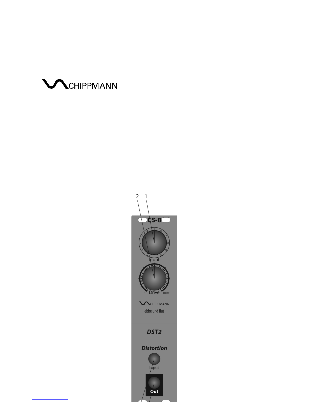
7.1 Fron panel
Fig. 1 shows the front panel with consecutively numbere controls an jacks.
Fig. 1
CS-8 Series DST2 Rev1.0, Dec. 2018
-9-
1. Inpu Controller – attenuates the incoming au io signal at
jack 3
between 0 an 1
2. Drive Controller – rives the input signal at
jack 3
into the saturation or
har clipping, resp. from 1% to 100%
3. Inpu jack (input) – routes the applie signal via
Cont. 1
to the istortion
input
4. Ou jack (output) – provi es the istortion output signal
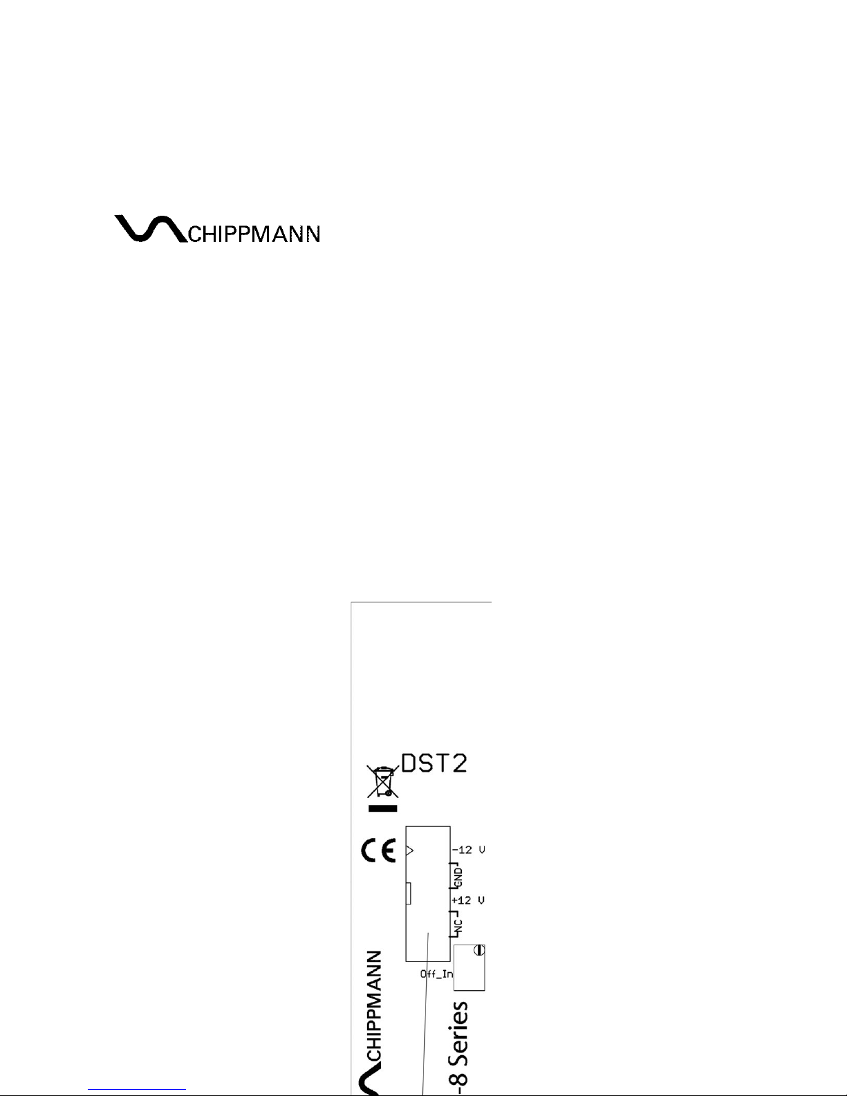
7.2 Back
Fig. 2 shows the back of the mo ule with consecutively numbere elements.
Fig. 2
CS-8 Series DST2 Rev1.0, Dec. 2018
-10-
7.3 Ini ial opera ion
The power connector’s (1) pin-out in top view (refer to fig. 2) is assigne as
follows:
Bottom to top, left to right. Thus pin 1 is locate at bottom left, pin 2 above pin
1 etc. Pin 15 is at bottom right, pin 16 at top right.
Pin 1, 2 = -12 V (labelle with a triangle)
Pin 3-8 = GND (groun , 0 V), locate outwar on all jacks
Pin 9, 10 = +12 V
Pin 11-16 = not in use
To hook up power to the mo ule, connect one of the IDC-jacks of the inclu e
flat ribbon cable to the connector (refer to fig. 2). Observe gui e key for the
polarity of the connector in or er to avoi pin reversal. The red ag of the
cable is o ma ch he riangle-label.
8. MODULE DESCRIPTION
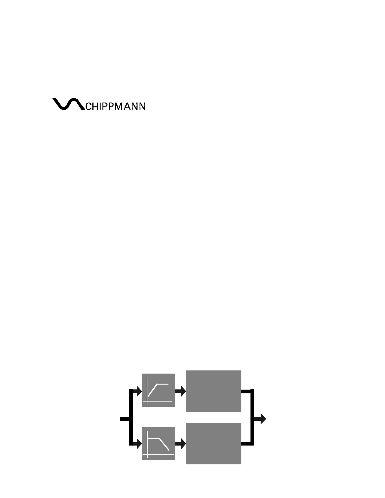
S ruc ure
Distortion
Distortion
LP
HP
Fig. 3 Structure of DST2
Fig. 3 shows the structure of the istortion unit. The input signal will be
spectral separate by a high-/low-pass crossover network at 113 Hz before
fee ing the respective istortion stage an mixing the results together.

CS-8 Series DST2 Rev1.0, Dec. 2018
-11-
Inpu
This section inclu es the jack 3 (Input) an the controller 1 (Input). The input
signal to be processe by the DST2 flows from
jack 3,
capacitively ecouple ,
to the Cont. 1 where it is attenuate between 0 (-∞ b) an 1 (0 b). To obtain
a signal gain of 1 (input to output, "Drive" at full CCW) at the signal output
Out
Cont. 1
has to be set to full CW.
Drive
This section inclu es the controller 2 (Drive) an the jack 4 (Out). With rising
movement from left to right of Drive in irection to 100% on the scale the
input signal will be riven more an more into saturation. With input signals of
about 4 Vpp or larger a secon kin of istortion starts at position 3 o'clock of
Drive, which a s some more "sweet" harmonics to the result at jack 4 (Out).
Hint: This dis or ion is always working, so at Drive at 1%, too! If a totally
clear signal is wishe , the DST2 shoul be remove from the signal path.
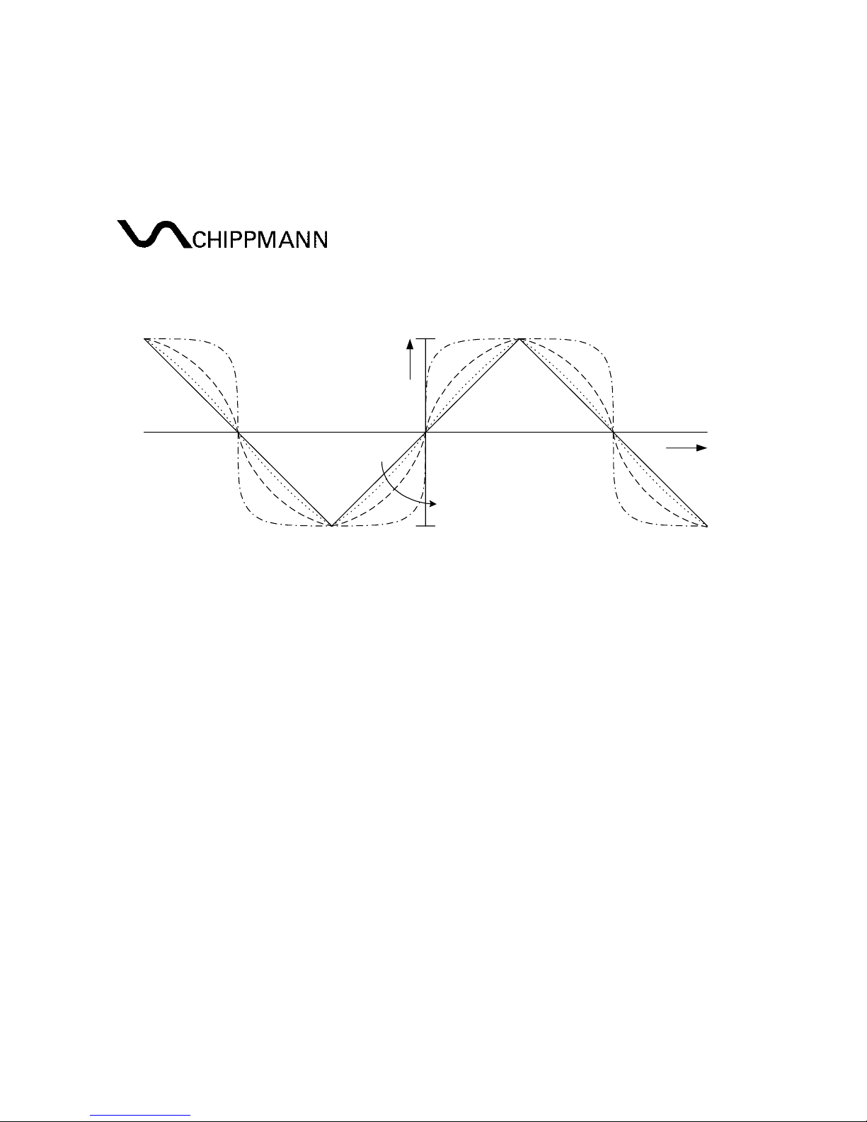
Fig. 4. shows the transfer function of a istortion stage for rising Drive-
positions (left to right). Let be the momentary input voltage values on the
horizontal axis an the respective output value on the vertical one.
Signal Input Voltage
Signal Output Voltage
left to right
left to right
Fig. 4
Fig. 5 gives an illustration of the signal eformation for a triangle input signal
(soli line) for rising Drive values (left to right) in the time omain.
CS-8 Series DST2 Rev1.0, Dec. 2018
-12-
time
Signal Output Voltage
left to right
Fig. 5

CS-8 Series DST2 Rev1.0, Dec. 2018
-13-
9. TECHNICAL DATA AND SIGNAL VALUES
9.1 Technical Da a (in general)
Input- an output-jacks: mono jack jacks 3.5 mm (1/8”)
Input jacks have groun e switch (0 V)
Power: -12 V / +12 V (polarity
protection)
Power consumption: max. 30 mA (for both
supplies ±12 V)
Proper ambient temperature: 0 °C – +55 °C / 32F – 131F
Net weight (mo ule only): approx. 55 g / 0,12 lbs
Dimensions (W x H x D): 6 PU (30.2 mm) x
3 HU (128.5 mm) x 40 mm
Installation epth (behin the panel) <20 mm
9.2 Signals and ra ings
Input impe ance (jack 3, Drive from CCW - CW): 11 kΩ - 1 kΩ
Maximum input voltage at jack (3): 10 Vrms (28 Vpp for sinus)
Output noise:
Drive = 1%: 40 µVrms ≅ -88 bV
Drive = 30-50%: 10 µVrms ≅ -100 bV
Drive = 100%: 30 µVrms ≅ -90 bV

Other manuals for CS-8 Series
3
This manual suits for next models
1
Table of contents
Other Chippmann Music Equipment manuals


