Beast BCR130/5 BG User manual

OPERATING MANUAL
DIAMOND CORE RIGS
®
BCR130/5 BG
BCR130/5 MG
BCR164/6,5
BCR300/12
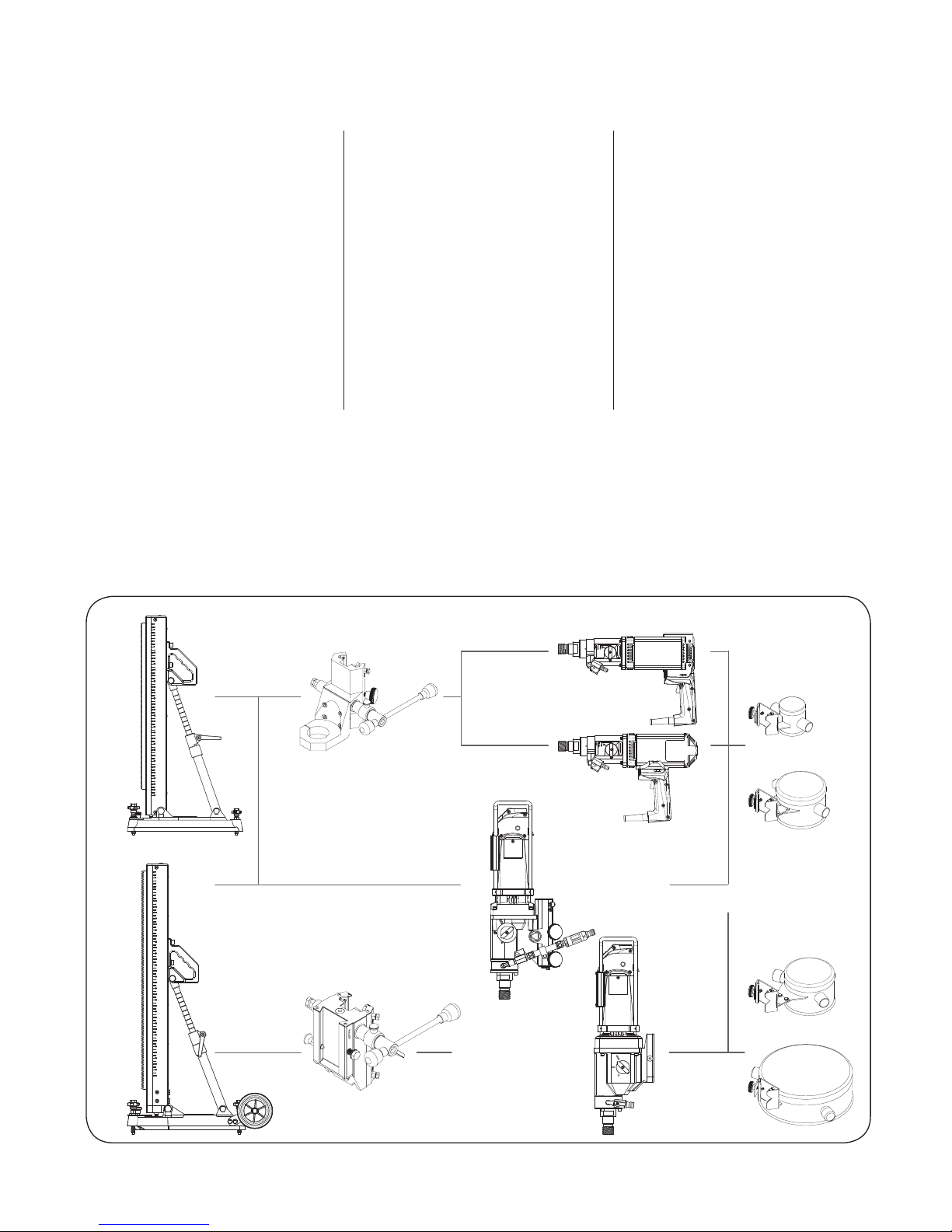
Compact
Large
BCR130/5 MG
BCR130/5 BG
BCR300/12
BCR164/6,5
II
CONTENTS
General Power Tool Safety Warnings ... 6
For your safety ........................7
Tool Specifications ....................8
Operating Controls.................... 9
Safety guidelines......................9
Intended Use .........................9
Before Use ............................ 9
Initial Operation .....................10
Hand held drilling....................10
–Hand held wet drilling.............10
–Hand held dry drilling .............11
Drilling with a drill stand .............11
Drill stand fixation ...................12
–Secure using assembly ............12
BCR130/164
8 - 66 mm
50 -131 mm
50 -131 mm
120 -270 mm
BCR300/12
–Vacuum pump fixation . . . . . . . . . . . . 12
Over head drilling....................13
–Mounting the water collecting ring 13
Transport and Storage ...............13
Maintenance and Cleaning ...........13
Troubleshooting .....................13
Replacement parts ...................15
Guarantee ...........................15
Environmental Protection ............15
Noise/Vibration Information..........15
Declaration of Conformity ............15
BCR130/5 BG
BCR130/5 MG
1
2
47
3
4
11
10
9
8
7
6
5
12
13
14
15
16
17
18
19
20
21
22
23
Compact
Compact
24
25
26
27
28
29
III
BCR130/164
8 - 66 mm
50 -131 mm
50 -131 mm
120 -270 mm
BCR300/12

BCR164/6,5 12
4
14
13
3
16
15
17
20
21
22
1
2
47
9
19
8
7
6
23
31
6
32
33
34
32
33
34
BCR130/5-164/6,5
BCR300/12
Compact
IV
BCR300/12 12
4
36
35
14
13
3
15
17
30
20
21
22
1
2
47
9
19
8
7
6
23
38
39
40
41
42
43
44
45
46
Large
24
25
26
27
28
37
29
Large
V
Vacuum
pump

® BCR130/5-BCR164/6,5-BCR300/12
6 BEAST CORE RIG OPERATING MANUAL
GENERAL POWER TOOL SAFETY
WARNINGS
WARNING: Read all safety warn-
ings and all instructions. Failure to
follow the warnings and instruc-
tions may result in electric shock,
fire and/or serious injury.
Save all warnings and instructions
for future reference.
The term “power tool”in the warnings refers to
your mains-operated (corded) power tool or
battery-operated (cordless) power tool.
1) Work area safety
a) Keep work area clean and well lit. Cluttered
or dark areas invite accidents.
b) Do not operate power tools in explosive
atmospheres, such as in the presence of
flammable liquids, gases or dust. Power
tools create sparks which may ignite the
dust or fumes.
c) Keep children and bystanders away while
operating a power tool. Distractions can
cause you to lose control.
2) Electrical safety
a) Power tool plugs must match the outlet.
Never modify the plug in any way. Do
not use any adapter plugs with earthed
(grounded) power tools. Unmodified plugs
and matching outlets will reduce risk of
electric shock.
b) Avoid body contact with earthed or
grounded surfaces, such as pipes, radia-
tors, ranges and refrigerators. There is an
increased risk of electric shock if your body
is earthed or grounded.
c) Do not expose power tools to rain or wet
conditions. Water entering a power tool will
increase the risk of electric shock.
d) Do not abuse the cord. Never use the cord
for carrying, pulling or unplugging the
power tool. Keep cord away from heat, oil,
sharp edges and moving parts. Damaged or
entangled cords increase the risk of electric
shock.
e) When operating a power tool outdoors,
use an extension cord suitable for outdoor
use. Use of a cord suitable for outdoor use
reduces the risk of electric shock.
f ) If operating a power tool in a damp location
is unavoidable, use a residual current device
(RCD) protected supply. Use of an RCD
reduces the risk of electric shock.
3) Personal safety
a) Stay alert, watch what you are doing and use
common sense when operating a power
tool. Do not use a power tool while you are
tired or under the influence of drugs, alco-
hol or medication. A moment of inattention
while operating power tools may result in
serious personal injury.
b) Use personal protective equipment. Always
wear eye protection. Protective equipment
such as dust mask, non-skid safety shoes,
hard hat, or hearing protection used for
appropriate conditions will reduce personal
injuries.
c) Prevent unintentional starting. Ensure the
switch is in the off-position before connect-
ing to power source and/or battery pack,
picking up or carrying the tool. Carrying
power tools with your finger on the switch
or energising power tools that have the
switch on invites accidents.
d) Remove any adjusting key or wrench before
turning the power tool on. A wrench or a
key left attached to a rotating part of the
power tool may result in personal injury.
e) Do not overreach. Keep proper footing and
balance at all times. This enables better con-
trol of the power tool in unexpected situa-
tions.
f ) Dress properly. Do not wear loose cloth-
ing or jewellery. Keep your hair, clothing
and gloves away from moving parts. Loose
clothes, jewellery or long hair can be caught
in moving parts.
g) If devices are provided for the connection
of dust extraction and collection facilities,
ensure these are connected and properly
used. Use of dust collection can reduce
dust-related hazards.

® BCR130/5-BCR164/6,5-BCR300/12
BEAST CORE RIG OPERATING MANUAL 7
4) Power tool use and care
a) Do not force the power tool. Use the correct
power tool for your application. The correct
power tool will do the job better and safer
at the rate for which it was designed.
b) Do not use the power tool if the switch does
not turn it on and off. Any power tool that
cannot be controlled with the switch is dan-
gerous and must be repaired.
c) Disconnect the plug from the power source
and/or the battery pack from the power tool
before making any adjustments, changing
accessories, or storing power tools. Such
preventive safety measures reduce the risk
of starting the power tool accidentally.
d) Store idle power tools out of the reach of
children and do not allow persons unfamil-
iar with the power tool or these instructions
to operate the power tool. Power tools are
dangerous in the hands of untrained users.
e) Maintain power tools. Check for misalign-
ment or binding of moving parts, breakage
of parts and any other condition that may
affect the power tool’s operation. If dam-
aged, have the power tool repaired before
use. Many accidents are caused by poorly
maintained power tools.
f ) Keep cutting tools sharp and clean. Properly
maintained cutting tools with sharp cutting
edges are less likely to bind and are easier to
control.
g) Use the power tool, accessories and tool bits
etc. in accordance with these instructions,
taking into account the working conditions
and the work to be performed. Use of the
power tool for operations different from
those intended could result in a hazardous
situation.
5) Service
a) Have your power tool serviced by a qualified
repair person using only identical replace-
ment parts. This will ensure that the safety of
the power tool is maintained.
FOR YOUR SAFETY
Working safely with this machine
is possible only when the operat-
ing and safety information are
read completely and the instruc-
tions contained therein are
strictly followed. Before using for
the first time, ask for a practical
demonstration.
Before working on the machine itself,
pull the mains plug.
Be careful of hidden electrical lines or
gas and water pipes. Check the work-
ing area, e. g., with a metal detector.
Wear safety goggles and
hearing protection.
•Before commencing work, the GFCI protec-
tive switch must be checked for proper
functioning.
•Before commencing work consult the
responsible structural engineers, architects
or site supervision about any planned bor-
ings, especially when cutting through rein-
forcing steel.
•The machine may only be operated using
a power supply with protection earthing
according to the regulations.
•The machine may not be operated by per-
sons under the age of 16 years.
•The drill stand must always be mounted
firmly and must not be able to move during
drilling.
•Only mount the drill stand on an even, firm
and smooth surface using the vacuum
pump.
•When carrying out “over” head wet cut core
drilling, a water collecting ring and water
suction are always to be used. These must
be in perfect condition.
•When drilling “over” head always secure the
drill stand with the assembly.
•Prevent the drilling core from falling.

® BCR130/5-BCR164/6,5-BCR300/12
8 BEAST CORE RIG OPERATING MANUAL
Vacuum pump
•Avoid any constrictions in the suction hose,
e.g. due to dirt accumulation, squeezing,
bending or stretching.
•Check the suction hose each time before
use. Renew any leaking or damaged parts.
•Keep the cooling air vents on the pump free
and clean.
•The underlying surface of the drill stand
must be clean, firm, smooth, dry and with-
out any holes. For further safety regulations,
see the operating instructions for the drill
stand.
•Caution: The machine automatically
switches on immediately after inserting the
plug in the mains and becomes hot after a
long period of use.
•Always connect the core drill and the vac-
uum pump to the same power outlet.
•Do not carry out any changes or modifica-
tions to the machine.
•Should the machine have an operational
fault, the vacuum function will remain for a
short time. The cohesion is depe dent upon
the underlying surface and seal retention.
Stop working immediately and remove the
drill stand completely.
Use only original BEAST/B+BTec parts and
accessories.
TOOL SPECIFICATIONS
Drill BCR130/5 BG BCR130/5 MG BCR164/6,5 BCR300/12
Input power (Watt) 2.000 W 2.000 W 2.000 W 2.400 W
Motor (Voltage) 110V 110V 110V 110V
(Frequency/Amps) 50-60 Hz/16 A 50-60 Hz/16 A 50-60 Hz/16 A 50-60 Hz/20A
No-load speed 1-2-3 min-1 900-2.180-4.290 900-2.180-4.290 620-1.400-3.500 450-900-1.600
Bore diameter
Wet/Dry 1. Gear Ø mm 55-130/55-164 55-130/55-164 101-164/- 120-300/-
Wet/Dry 2. Gear Ø mm 25-60/25-60 25-60/25-60 41-101/- 60-150/-
Wet/Dry 3. Gear Ø mm 8-35/8-35 8-35/8-35 10-41/- 25-80/-
Dimensions L x B x H cm 44,5 x 28 x 11,5 44,5 x 30 x 11,5 59 x 20 x 22 60 x 27 x 22
Weight
Motor 7,5 kg* 7,5 kg* 12,9 kg** 12 kg
Guide block 4,1 kg 4,1 kg - 3,9 kg
Drill Stand Compact 10,3 kg 10,3 kg 10,3 kg -
Drill Stand Large 13,9 kg 13,9 kg 13,9 kg 13,9 kg
Safety class (EN-IEC 61029) / I / I / I / I
Safety class (IP Code) IP54 IP54 IP54 IP54
* Drill BCR 130 overall weight. ** Incl. guide block.
Vacuum pump
Rated voltage 110 Volt Maximum vacuum -800 mbar
Rated input 500 Watt Weight 11,2 kg

® BCR130/5-BCR164/6,5-BCR300/12
BEAST CORE RIG OPERATING MANUAL 9
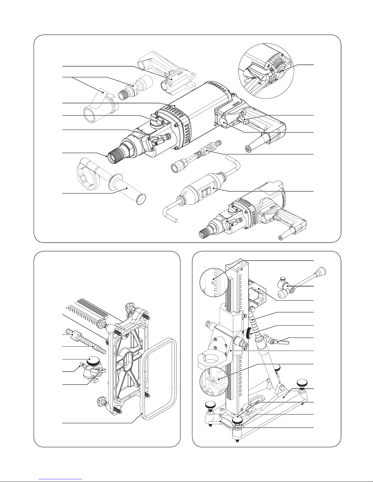
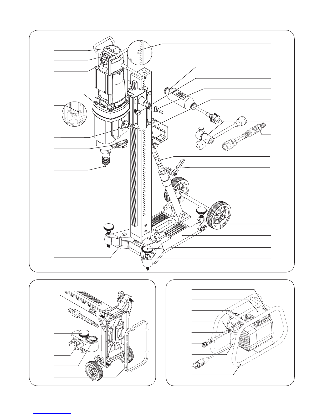
OPERATING CONTROLS
1LED motor load
2On/Off switch
3Waterflow Indicator
4GFCI protective switch
5Grip
6Hex collet
7Water tap
8Speed selection switch
9Ventilation slots
10 Dry Drilling Kit
11 2nd Back Grip
12 Safety screw
13 Feed lever
14 Stand Grip
15 Rod with scale for drill angle adjustment
16 Locking screw
17 Clamping lever for 15
18 Guide block for BCR 130
19 Limit stop plate
20 Base plate
21 Adjusting screws
22 Safety bolt
23 Centering plate
24 Spindle nut
25 Screw assembly
26 Vacuumblock fastening screw
27 Connection for vacuum pump
28 Ventilating tap
29 Seal
30 Transportation wheels
31 Drill bit
32 Rubber cover
33 Fastening screw for water collecting ring
34 Water collecting ring
35 Clamping lever for Quick Release Guide
36 Safety bolt Quick Release Guide
37 Pressure gauge vacuum kit
38 Air vent
39 Filter cap
40 Vacuum gauge
41 Hose clip
42 Suction hose
43 Quick coupling
44 Fluid collecting container with float
45 Mains plug
46 Frame
47 Overload safety switch
*Not all of the accessories illustrated or described are
included as standard delivery.
SAFETY GUIDELINES
The definitions below describe the level of sever-
ity for each warning. Please read the operating
manual and pay attention to these symbols.
DANGER: Indicates an imminently
hazardous situation which, if not
avoided, will result in death or seri-
ous injury.
WARNING: Indicates a potentially
hazardous situation which, if not
avoided, could result in death or
serious injury.
CAUTION: Indicates a potentially
hazardous situation which, if not
avoided, may result in minor or
moderate injury.
NOTE: Indicates a practice not
related to personal injury which, if
not avoided, may result in property
damage.
INTENDED USE
The machine is intended for drilling into concrete
and reinforced concrete, when being used in con-
junction with diamond core bits for wet drilling
and a suitable water supply. BCR130/5 can also be
used for dry drilling in masonry and other build-
ing materials with the dry drilling kit.
The vacuum pump is intended for the fixation of
drillstands Compact and Large. The pump is only
designed for sucking in air, and no other gases or
fluids.
For damage caused by usage other then
intended, the user is responsible.
BEFORE USE
When drilling through walls or floors, make
absolutely sure that there are no obstacles
in the adjoining rooms and cordon off the
building site. Prevent the drilling core from
falling.
® BCR130/5-BCR164/6,5-BCR300/12
10 BEAST CORE RIG OPERATING MANUAL
Always use the correct supply voltage: The
power supply voltage must match the informa-
tion quoted on the tool identification plate.
INITIAL OPERATION
Functional test for the GFCI protective
switch 4
WARNING: The ON/OFF switch 2
must be switched off, in order to
avoid unintentional starting of the
machine when carrying out the
functional test of the GFCI protec-
tive switch 4.
Before commencing work, check that the GFCI
protective switch is functioning properly:
•Press the «ON» button on the GFCI protective
switch. The red control lamp indicates when
the protective switch is ready for operation.
•Press the «TEST» button. The control lamp
must go off.
Setting the speed range
CAUTION: Actuate the gear selector
switch only when the machine is at
a standstill.
The gear selector switch allows for pre-selection
of three speed ranges.
Position •: low speed
Position ••: medium speed
Position •••: high speed
Switching On/Off
Switching on: Press the ON/OFF switch 2
(position “1”).
Switching off: Press the ON/OFF switch 2
(position “0”).
WARNING: Use BCR130/5 only in
combination with a drillstand when
drilling in first gear, Position 1 (low
speed).
Overload Protection
The LED 1indicates the motor load, whereby the
following conditions are distinguished:
Blue: No load
Green: Regular drilling load
Red: Overload
Excessive overloading will shut down the motor.
After the motor has cooled off, the motor can be
switch on again with the Overload Safety Switch
47.
Connecting the water feed
•Close the water tap 7.
•Connect the water feed hose to the water tap
or the water pressure tank.
•When using the water pressure tank, make
sure that there is sufficient pressure when
working.
•Check the waterflow indicator 3.
Mounting the drill bit 31
•Clean and grease the thread on the drill bit
31 and the tool holding fixture 6.
•Screw a core bit 31 onto the tool holder 6
and tighten.
Removing the drilling core
•Break off the drilling core and remove.
HAND HELD DRILLING
WARNING: Hand held drilling only
for BCR130/5. Maximum bit diame-
ters:
•Wet drilling in concrete: Ø 40 mm.
•Dry drilling in masonry: Ø 164 mm.
Hand held wet drilling
•For wet drilling open the water valve 7and
switch on the machine 2.
•Hold the machine as rigidly as possible.
•Always use the grip 5at the front of the
machine.
•Start drilling by keeping the machine at a
slight angle.
•After the bit is guiding itself into the material,
swivel back the machine into the right angle
position.

® BCR130/5-BCR164/6,5-BCR300/12
BEAST CORE RIG OPERATING MANUAL 11
Hand held dry drilling
Mounting the dry drilling kit 10
A
B
•Loosen the frontgrip 5of the core drilling
machine.
•Mount part A of the dry drilling kit onto the
drill spindle 6.
•Slide the dry drilling sleeve (B) on part A in
the desired position for the vacuum cleaner.
•Tighten the grip 5.
•Mount the hose of a industrial vacuum
cleaner on the sleeve (B).
•Mount a core drill 31 onto the drill spindle 6.
Using the dry drilling kit 10
•Drilling is only possible if the masonry is
absolutley dry. Use a powerful industrial dust
exhauster. Change the filter regularly, there is
risk of obstruction.
•Hold the machine as rigidly as possible.
•Always use the grip 5at the front of the
machine.
•Start drilling by keeping the machine at a
slight angle.
•After the bit is guiding itself into the material,
swivel back the machine into the right angle
position.
WARNING: The machine has a very
high torque, especially in the first
gear. Therefor drill only extremely
concentrated, especially when
working in first gear and with
diameters of more than 60 mm. In
case of sudden blocking of the core
bit the machine, despite the safety
clutch, might get out of control and
hurt you considerably.
DRILLING WITH A DRILL STAND
Guide block setting
AB
When using a drill stand a right setting of the
guide block is required. Guide blocks for BCR core
drilling machines features slide strips for fine tun-
ing on the drill stand.
•Loosen the safety nuts (A) using the supplied
wrench 13.
•Adjust the bolts (B) for an flexible sliding of
the guide block on the drill stand.
•Secure then the bolts with the safety nuts (A).
Using Quick Release Guide BCR300/12
You can easy release the core drilling machine
BCR300/12 from its Quick Release Guide and so
from the drill stand.
•Loosen the guide block safety bolt 36 with
the feed lever 13.
•Pull the machine safety lock.
•Slide the core drilling machine gently from
the guide block.
•When replacing the machine secure accord-
ingly.
Aligning the drill stand
•Set up the drill stand at the drilling location.
•Pull the safety bolt 22 and rotate the center-
ing plate 23 forwards, until it snaps in.
•Align the drill stand in such a manner that
for the used machine the tip of the centering

® BCR130/5-BCR164/6,5-BCR300/12
12 BEAST CORE RIG OPERATING MANUAL
plate is located directly above the required
drilling location.
•Fasten the drill stand.
Setting the drilling angle
•Loosen the clamping lever 17.
•Push in or pull out the rod 15 until the
desired drilling angle is shown on the scale.
•Tighten the clamping lever 17.
Drilling
•Always ensure a adequate anchorage in the
underground.
•Open the water tap 7.
•Actuate the ON/OFF switch 2.
•Drill using an even forward feed. Do not over-
load the machine.
•The leaking water should be milky and not
clear.
•Always loosen the locking screw 16 (BCR
130/5-164/6,5) or the clamping lever 35 (BCR
300/12) when drilling.
•After drilling switch the machine off and shut
off the water tap.
DRILL STAND FIXATION
CAUTION: The drill stand must
always be mounted firmly and
must not be able to move during
drilling.
Secure using assembly
•Drill the rawlplug hole Ø 15/16 mm (see
instruction rawlplug).
•Insert rawlplug. SD M12
•Screw in assembly 25.
•Align the drill stand.
•Fasten the drill stand with the spindle nut 24.
Vacuum pump fixation
Setting up the vacuum pump
•Position the machine horizontally. Maximum
tilt of 10°.
•Fasten, mount suction hose 42 and fasten
with hose clip 41.
WARNING: Maximum drilling diam-
eter of 100 mm. Mount the drill
stand on an even, firm and smooth
surface using the vacuum pump,
never “over” head. Always connect
the core drill and the vacuum pump
to the same power outlet. Never
turn off the vacuum pump during
operation.
•Install the vacuum kit.
•Turn the fixation screws 21 ensuring, how-
ever, that the seal 29 is not squeezed.
•Align the drill stand.
•Mount the suction hose to the connection for
the vacuum pump 27.
•Close the ventilating tap 28.
•Connect quick coupling 43 to vacuum kit 27
on the drill stand.
•The machine has no On/Off switch; it is put
into operation by inserting the mains plug 45
into the socket.
•The existing vacuum can be read from the
vacuum gauge 40.
•The vacuum gauge 40 must show a vacuum
of below -0.65 bar. If not check for leakage.
•Do not commence work until the required
vacuum has been reached.
•Watch the vacuum gauge 40 while working.
If the vacuum rises above -0.65 bar, inter-
rupt the work immediately and completely
remove the drill stand.
Empty the fluid collecting container 44
•If fluid is sucked in during operation, the
vacuum will no longer be maintained. Pull
the mains plug out immediately.
•Unscrew the fluid collecting container 44.
•Remove the float and empty the container.
•Replace the float and screw on the container
tightly again.
CAUTION: The machine becomes
hot after a long period of use. Do
not touch the machine directly
after operating it.

® BCR130/5-BCR164/6,5-BCR300/12
BEAST CORE RIG OPERATING MANUAL 13
OVER HEAD DRILLING
DANGER: When drilling “over” head
always secure the drill stand with
the assembly.
DANGER: When drilling “over”
head, always use a water collecting
ring and a industrial wet-type vacu-
um cleaner!
Mounting the water collecting
ring 34
•Loosen the fixation screw 33 on the water
collecting ring 34.
•Push the water collecting ring 34 onto the
drill stand and press it firmly against the
material to be drilled.
•Tighten fixation screw 33.
•Connect a industrial wet-type vacuum
cleaner.
•When using the water collecting ring,
attach a protective cover 32 onto it and drill
through. Remove te drilled part of the cover
32 from the core bit.
TRANSPORT AND STORAGE
CAUTION: Danger of injury and
damage! Pay attention to the
weight of the appliance when
transporting it.
•Clean the machine and remove the drilling
dirt.
•Transport the machine and core bit sepa-
rately.
•Blow out remaining water from hose and
machine when it freezes.
•This appliance may only be stored inside a
building.
MAINTENANCE AND CLEANING
Clean the machine with water and a brush after
use and lubricate the moveable parts as well as
the rack with a silikon spray.
Always keep the machine and cooling air vents
free and clean. It must always be kept in a dry,
frost-free place.
Clean the filter of the vacuum pump
The condition of the filter must be checked at
regular intervals.
•Loosen the four screws with hexagonal recess
on the bottom of the frame 46.
•Unscrew filter cover 39.
•If necessary, renew filter parts.
•Screw on filter cap 39 again. The arrows on
the cap must point in the direction of flow of
the sucked in air.
•Mount the pump on the frame 46 again.
TROUBLESHOOTING
For malfunctions that are not specified in this
chapter, when in doubt or when explicitly indi-
cated, seek assistance from an authorized service
facility.

® BCR130/5-BCR164/6,5-BCR300/12
14 BEAST CORE RIG OPERATING MANUAL
Problem Possible cause Possible solution
The motor doesn’t work. Defective motor.
Defective cable of plug.
Defective switch.
Contact customer service. Never
repair the motor yourself.
Danger!
GFCI protective switch is not
switched on, test!
Have inspected by a electrical
specialist and replaced if neces-
sary.
Contact customer service.
Motor makes too much noise. Damaged windings.
The carbon brushes of the
machine are worn.
Have the motor inspected by
customer service.
Motor mildly overheats. Motor overload.
Motor doesn’t cool sufficiently
Prevent motor overload when
drilling.
Remove the dust from the
motor, so that the cool air can
flow.
Motor runs. Core bit doesn’t
rotate.
Gearing defective. Have the machine inspected by
the service facility.
Rate of drilling progress
decreases.
Core bit segments polished.
Water pressure/water flow rate
too high.
The core is stuck in the core bit.
Maximum drilling depth
reached.
Core bit defective.
Gearing defective.
The clutch is releasing prema-
turely or slipping.
Sharpen the core bit on a
sharpening plate while water is
flowing.
Use the feed lever to reduce the
water flow rate.
Remove the core.
Remove the core and use a core
bit extension.
Check the core bit for damage
and replace if necessary.
Have the machine repaired at a
service center.
Have the machine repaired at a
service center.
Motor cuts out. The core bit has been jammed
for too long.
Electric power failure.
Electronics defective.
Free the core bit. Switch the
motor off and then on again.
Check the plug connections,
electric power supply and GFCI
protective switch.
Have the machine repaired at a
service center.
Water leakage at the water
swivel or gear housing.
Shaft seal defective.
Water pressure is too high.
Have the machine repaired at a
service center.
Reduce the water pressure.

® BCR130/5-BCR164/6,5-BCR300/12
BEAST CORE RIG OPERATING MANUAL 15
REPLACEMENT PARTS
If – in spite of meticulous manufacturing and test-
ing processes – the device breaks down, have it
serviced by a BEAST/B+BTec Service.
GUARANTEE
For this BEAST/B+BTec appliance we grant a war-
ranty in accordance with the statutory/country-
specific provisions as from date of purchase (by
evidence of invoice or delivery note). Damage
that has occurred will be corrected either by
replacement or by repair.
Damage caused by improper handling is
excluded from the warranty.
Claims can be recognized only if the appliance
is presented in a not-disassembled manner to a
BEAST/B+BTec branch office, your BEAST/B+BTec
field service employee or a customer service office
for power tools authorized by BEAST/B+BTec.
ENVIRONMENTAL PROTECTION
Do not dispose of the appliance with
domestic waste. Dispose of the appli-
ance only via an authorized waste man-
agement company or your municipal
waste management organisation.
Adhere also to the applicable regulations. In case
of doubt refer to your waste management organi-
sation. Recycle all packaging material in an envi-
ronmentally friendly manner.
NOISE/VIBRATION INFORMATION
Typically the A-weighted noise levels of the prod-
ucts are:
Sound pressure
level
NEN-ISO 11204
Sound power
level
EN-ISO 3744
130/5 93 dB (A) 103 dB (A)
164/6,5 89 dB (A) 98 dB (A)
300/12 90 dB (A) 101 dB (A)
Vac. pump 70 dB (A) 75 dB (A)
The typical hand-arm vibration is below 2,5 m/s2
(EN-ISO 5349).
Wear ear protection!
CDECLARATION OF CONFORMITY
We hereby declare that the appliance complies
with the relevant basic safety and health require-
ments of the EU Directives, both in its basic
design and construction as well as in the version
put into circulation by us. This declaration shall
cease to be valid if the device is modified without
our prior approval.
BCR130/5 BG/MG: EN-55014-1, EN-55014-2, EN-
IEC 61000-3-2, EN-IEC 61000-6-2, EN-ISO 5349-1,
EN-IEC 62841-1, EN-ISO 11204, EN 12348, EN-ISO
3744, EN-ISO 12100-1, EN-IEC 60204-1
BCR164/6,5: EN-55014-1, EN-55014-2, EN-IEC
61000-3-2, EN-IEC 61000-6-2, EN-ISO 5349-1, EN-
IEC 62841-1, EN-ISO 11204, EN 12348, EN-ISO
3744, EN-ISO 12100-1, EN-IEC 60204-1
BCR300/12: EN-55014-1, EN-55014-2, EN-IEC
61000-3-2, EN-IEC 61000-6-2, EN-ISO 5349-1, EN-
IEC 62841-1, EN-ISO 11204, EN 12348, EN-ISO
3744, EN-ISO 12100-1, EN-IEC 60204-1
Vacuum pump: EN-55014-1, EN-55014-2, EN-IEC
61000-3-2, EN-IEC 61000-6-2, EN-ISO 11204,
EN-1012-2, EN-ISO 3744
Conforms to the following standards or normative
documents 2006/42/EG, 2014/30/EU.
Subject to change without notice.
Zevenbergen, August 2016
R.G.W. van den Boogaart
General manager
B+BTec
Munterij 8
4762 AH Zevenbergen
P.O. Box 100
4760 AC Zevenbergen
The Netherlands

110 V
BM1604
LACKMOND.COM
BEMBCR-1612V2
This manual suits for next models
3
Table of contents
Popular Drill manuals by other brands

ALFRA
ALFRA 18400 Rotabest RB 35B Operation manual

EINHELL
EINHELL TE-ID 750/1 E Original operating instructions

Toolson
Toolson PRO-HM 9 MAX Original operating instructions

Hilti
Hilti SFC 22/14-A operating instructions

Parkside
Parkside KH 3133 BENCH DRILL manual

ACDelco
ACDelco ARD20129 Product information manual


