Becker Rhotheta SAR DF 517 User manual

Electronic Search
Electronic Search
with the Becker and G1000

Becker SAR DF 517
Becker SAR DF 517
System Components
System Components
Control-Display Unit (CDU)
Antenna-Receiver Unit (ARU)
Two Primary components

Becker SAR DF
Becker SAR DF-
-517
517
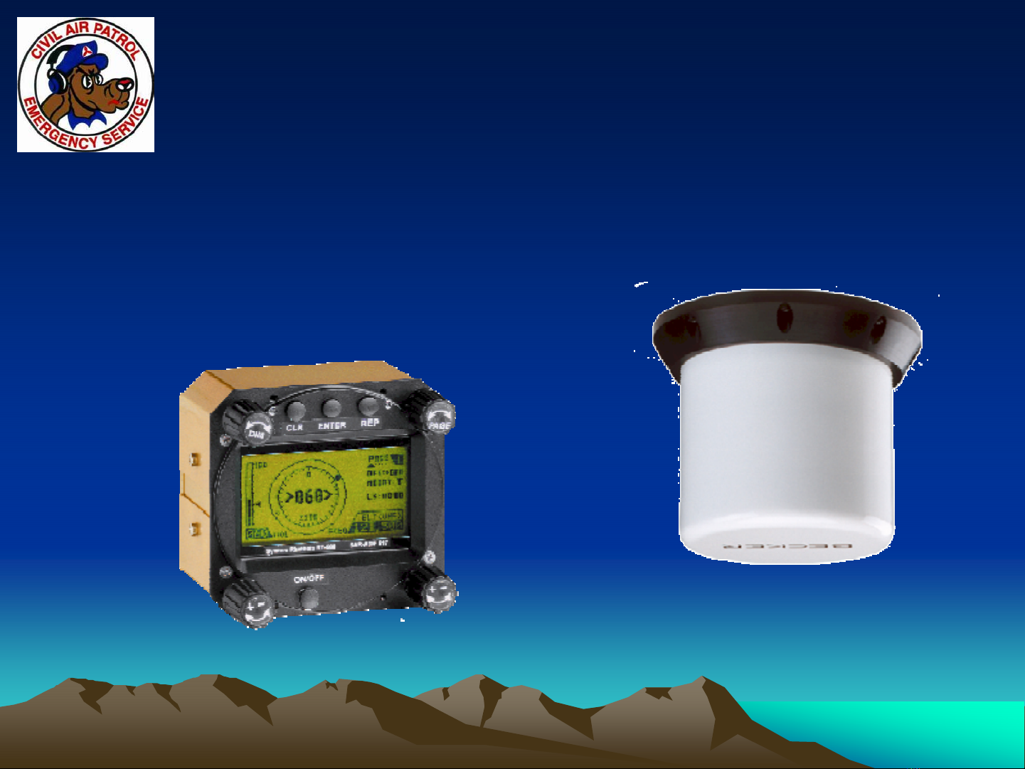
•The Becker SAR DF-517 is an automatic
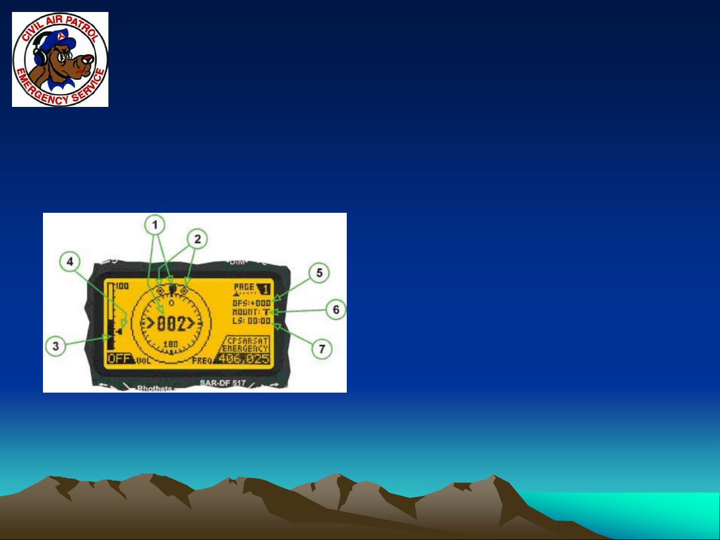
direction finder. It supports 121.5, 156.8, 243
and 406 MHz frequencies
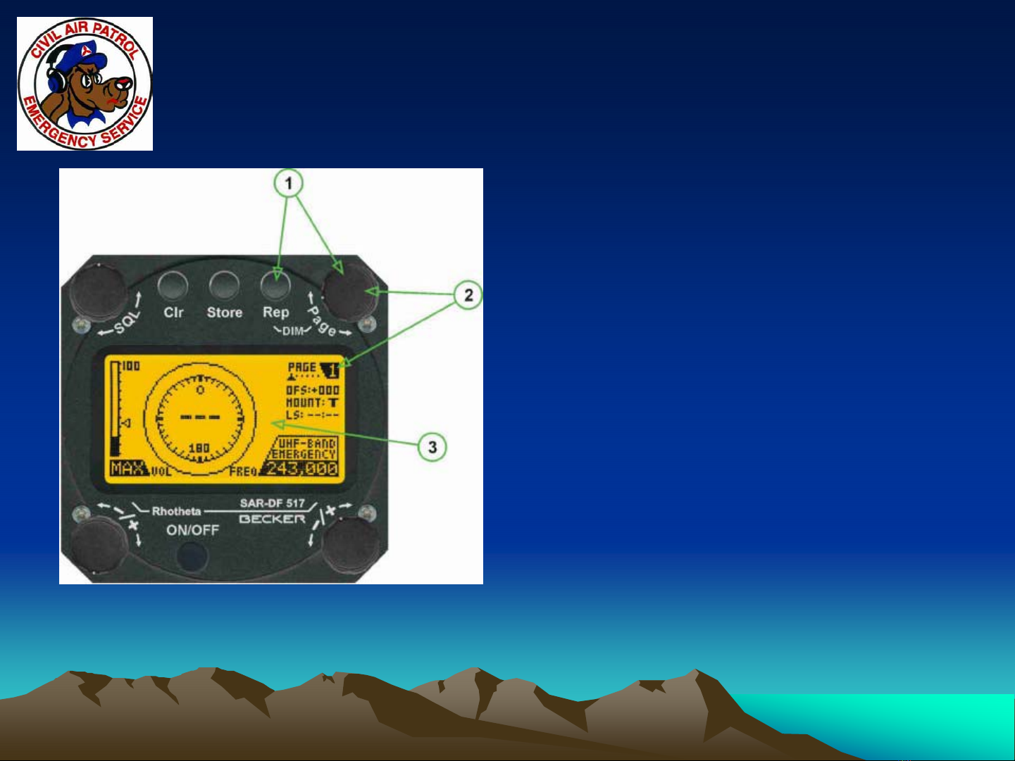
•The DF unit will display a bearing relative to the
nose of the aircraft for signals received
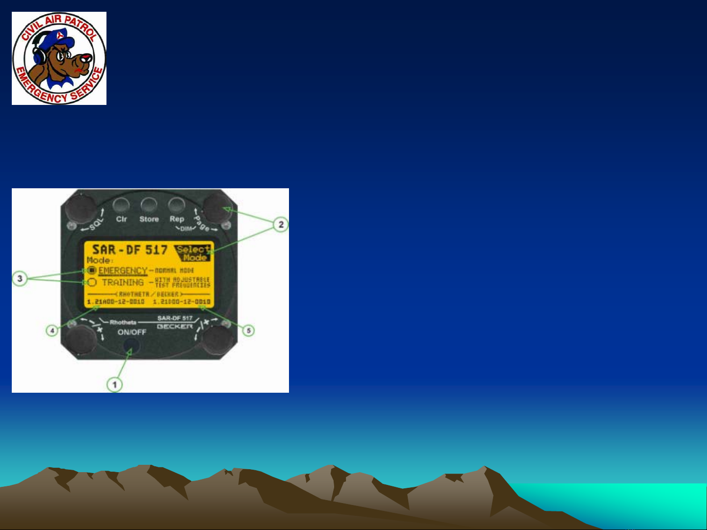
•There are two sets of frequencies that may be
selected. These are Emergency Mode or
Training Mode frequencies
•The Emergency Mode or Training Mode can
only be selected at power up

Power Up
Power Up
•If your aircraft is equipped
with Mission Master it must be
on for DF to operate
•On power up (1), verify
Emergency or Training mode.
To change the setting, turn
the page dial (2) and select
the appropriate mode (3).
Note: this option is only
available for the first 10
seconds after power up

Initial Setup
Initial Setup
•The Page dial (2) is
used to switch the
DF-517 between the
different pages
•By holding the Rep
button and rotating
the page dial (1) the
brightness can be
adjusted

DF
DF-
-517
517 DFing
DFing
•Select the desired frequency to
DF by using the bottom right
rotary dial (1) to select the
desired preprogrammed
frequency
•Use the volume (2) rotary dial to
set the volume level
•Once the desired frequency is
selected, use the SQL (3) dial to
select the squelch level

DF
DF-
-517
517 DFing
DFing cont.
cont.
•The DF signal can be heard by selecting
the AUX monitor toggle on the audio panel
•DFing is done using Page 1 or Page 2
•Page 1 displays a full circle with the signal
and bearing in 360o(this page is preferred)
•Page 2 displays a 90owindow with the
relative bearing and signal

DF
DF-
-517
517 DFing
DFing cont.
cont.
•(1) The signal and
relative bearing
•(3) Signal Strength
•(4) Squelch level
•Tracking frequency
406.025 in Emergency
mode
•Note that to DF a signal,
the squelch level must be
below the maximum
signal strength
DF-517 Page 1 Display

DF
DF-
-517
517 DFing
DFing cont.
cont.
•(1) Signal level and
relative bearing
•(2) Position error
•Tracking Freq.
121.650 in Training
Mode
DF-517 Page 2 Display

DF
DF-
-517 frequencies
517 frequencies

DF
DF-
-517
517
Adjusting Frequencies
•Page 6 enables you to adjust the
training frequencies
•(1) >±Select< rotary switch
selecting the trainings-frequency
(MHz/kHz)
•(2) >±< rotary switch changing
the frequency. Confirm the
changed value by pressing
pushbutton >STORE<
•(3) >STORE< Pushbutton to
confirm changed values

DF
DF-
-517
517
•The backlight is controlled by adjusting the
top panel light adjustment and setting the
annunciator panel switch in the “Night”
position
•Additional information on the Becker DF-
517 can be found in the manual
•Link at: http://www.becker-
avionics.de/666571_C_Images/ImgProduc
tsUSA/ProductsUSAPDF/ACF564.pdf

Operation
Operation
(1) ON/OFF
(2) PAGE
(3) MODE Indication of the actual
operation mode
(4) ARU Version Software version and
serial number of antenna-
receiver Unit
(5) CDU Version Software version and
serial number of control-display
Unit
Power-On and operation modes emergency or training

Bearing mode
Bearing mode
(pages 1 to 3)
(pages 1 to 3)
(1) FREQUENCY Selected
(2) VOLUME
(3) SQL Should be below the
noise level
(4) CLR For erasing the stored
bearing value
(5) STORE While bearing an AM
signal a 3 kHz sound is
superimposed to the audio
signal for technical reasons
(6) REPEAT Displays the last
valid bearing value with the
corresponding receive level

Display Readings
Display Readings
Page 1: 360°bearing Page 2: expanded 90° Page 3: bearing text
(1) Bearing value
(2) Spread Maximum deviation of unaveraged bearing. Good bearing results even with a spread of 45°as
a result of the averaging procedure
(3) Receive level Field strength
(4) Squelch level Squelch level must be below the noise level. Learn to recognize valid signals using the
marbles.
(5) Offset Corrects for antenna alignment (adjusted in the edit-menu)
(6) Mounting TOP mounted or BOTTOM mounted antenna
(7) LS: ---:--- Internal timer (LS meaning last signal) indicating the time since the last signal was received,
displayed in min /sec

Using the SCAN Mode
Using the SCAN Mode
The COSPAS/SARSAT signal on 406,025 MHz is only transmitted
every 50 sec (Pulse length of 400ms)
The scanning mode is possible with frequencies 406,025MHz or
121,500/243,000MHz or the matching training frequencies
The LS: ---:--- timer (LS meaning last signal) always displays the
time since last COSPAS/SARSAT signal was received in 406.025
MHz
Frequency displayed in scanning mode

Becker Antenna
Becker Antenna
•Antenna mounted on
bottom of aircraft
•Solid one piece unit
•This ELT does not
use wing null method

Mission Flow
Mission Flow

Prerequisites
Prerequisites
•Know your equipment.
–Be able to quickly set a user waypoint on the G1000
at your current position.
–Be able to set a user waypoint based on a lat-long.
–Know how to use OBS mode.
•Understand that the Becker will give you a best guess
direction even with NO signal. Don’t get fooled, use the
marbles.
–Understand how to go split on comms.

Before Launch
Before Launch
•Prepare
– What is the terrain in the area of the merge?
What direction and altitude gives the best
chance to pick up the signal.
– Have a plan of attack. Consider airspace,
terrain, weather, and other issues for safe
flight
Table of contents