BECKWITH ELECTRIC M-7651A D-PAC User manual
Instruction Book
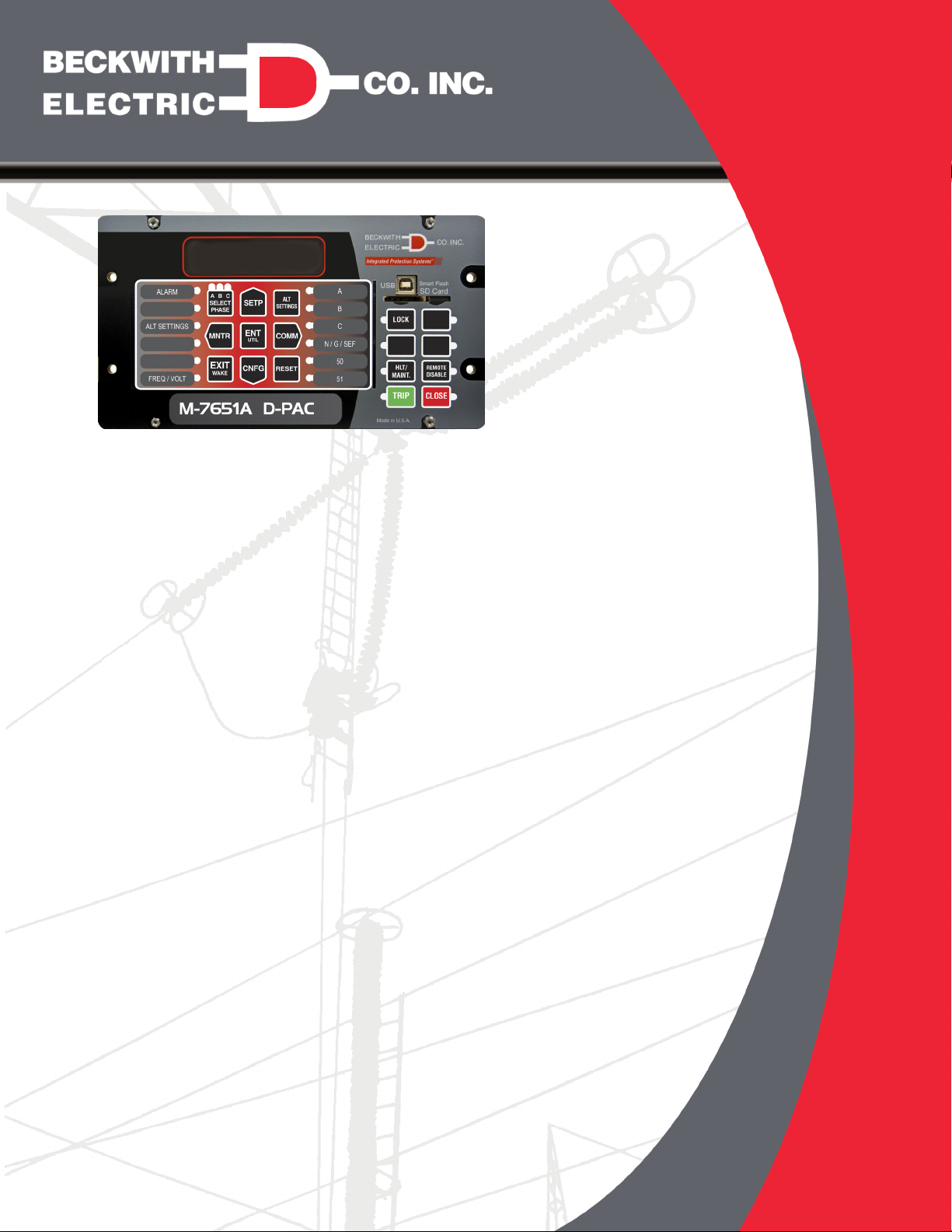
M‑7651A D‑PAC
Protection, Automation
and Control System
for Power Distribution Applications

TRADEMARKS
All brand or product names referenced in this document may be trademarks or registered trademarks
of their respective holders.
The content of this Instruction Book is provided for informational use only and is subject to change
without notice. Beckwith Electric Co., Inc. has approved only the English version of this document.
PROTECTION
Protection
• Over 30 Protection Elements for optimal
protection of Power Distribution Systems
• Ready to use advanced Protection Schemes
for applications including Feeder Protection,
Bay Control and DG Interconnection
Protection
• 8 Setting Profiles
• Comprehensive I/O Matrix provides visual
confirmation of enabled functions and
selected outputs improving security
• Arc Flash Protection including:
– Maintenance Mode
– Reverse Interlock Bus Protection
– (Optional) Optical with Overcurrent
Protection
• Compatible with Optical Point and Loop
Sensors
Automation/Communications
• Front panel USB and SD Card ports for local
programming and data transfer
• One or two optional serial ports (TIA‑232,
TIA‑485 or Serial Fiber)
• Optional single or dual Ethernet ports (copper
or fiber) with simultaneous multi‑user and
multi‑protocol support
• Protocols supported include:
– MODBUS, DNP3.0
– Optional: IEC61850
• Comprehensive Cyber Security tools for NERC
CIP Compliance
• IEEE 1686 Compliant
Control
• Four user programmable Inputs and Outputs,
expandable to twelve Inputs and twelve
Outputs, plus three Virtual Inputs
• User programmable front‑panel LEDs and
pushbuttons
Monitoring
• Power Quality Monitoring up to the 63rd
Harmonic including THD and TDD
• PQ Viewer (ITIC Curve)
• Sags, Swell and Sub‑Synchronous Transient
Detection
• Advanced Data Logging and Load Profile
Recorder
• 3500 Event Sequence of Events (SOE)
Recorder
• 100 DFR quality records of up to 480 cycles
each with an adjustable sampling rate up
to 128 s/c
IPScom®– Uncomplicated Software for
Complex Power System Applications
• Integrated Metering, DFR and PQ
Visualization Tools
• Search and filtering tools for
analysis of SOE, DFR and PQ
records
• IPSlogic Programmable Logic
Flexibility
• Fast and easy retrofitting
for most popular relays in
existing cutouts using
Beckwith's Adapter
Panel Technology™
Protection, Automation
and Control System
for Power Distribution
Applications
M‑7651A
D‑PAC
Industry Leader Since 1969
Made in the USA

–2–
M‑7651A D‑PAC – Specification
Time
Overcurrent
Ground, SEF
Inverse Time
Overcurrent
Ground, SEF
50G 51G
M-7651A D-PAC
59
VZ1
27
VZ1
Directional
Overcurrent
Ground, SEF
Inverse Time
Overvoltage Undervoltage
52
Breaker
3
46
60
FL
VT Fuse
Loss
Directional
Inverse Time
Overcurrent
• Phase
• Neg. Seq.
• Neutral
P
Q
N
67
Breaker
Failure
50
BF
Directional
Power
32
Time
Overcurrent
• Phase
• Neutral
Inverse Time
Overcurrent
• Phase with
Voltage Control/
Restraint
• Neutral
Port 1 +
TIA-232
TIA-485
Serial Fiber
Port 2 +
Ethernet
Fiber Optic
Or Copper
Port 3 +
Ethernet
Fiber Optic
Or Copper
Front Port
Type B USB
SD Card
IRIG-B
Port 4 +
TIA-232
TIA-485
Serial Fiber
+Optional Feature
Feature available at future date via firmware update
Negative
Sequence
Overcurrent
Definite Time
Inverse Time
50
51
Source
Load
67G
Protection, Automation and Control System for Power Distribution Applications
IPSlogic®
Programmable Logic
Eight Setting
Profiles
Over 30 Protection
Elements
Load Encroachment
Logic
Digital 86 Lockout
Hot-Line Tag/
Maintenance Mode
IRIG-B Time
Synchronization (TTL)
Web Browser Interface
Cold Load Pickup
Trip and Target
Counters
Self Diagnostics
Auto Restoration
Sequence of
Events Recording
Fault Locator
Data Logging
Digital Fault (Waveform)
Recording
THD/TDD Monitoring,
Alarming and Protection
Trip/Close Coil Monitor
Breaker
Wear Monitor
Synchrophasors p
(C37.118-2)
PQ Viewer
(ITIC Curve)
Demand/Energy
Metering
P
NP
N
25
79
Sync Check
F
R
P
o
w
e
r
45
55
5
5 55
1
PQ Monitoring
O
U
81
Frequency
• Over
• Under
4
81R
Frequency
Rate of
Change
2
Negative
Sequence
Overvoltage
47
Undervoltage
• Phase
• Phase-to-Phase
P
PP
27
4
Arc Flash Protection +
Multi-Shot Auto Recloser
Three Phase Ganged Operation +
XX
4
Number of
Elements
VY1, VY2, VY3, NY(3 V )
0
51V DT
IT
Loss of
Field
40
2
Protocols:
MODBUS
DNP 3.0 SAv2
Smart P2P (Peer-to-Peer)
IEC 61850 +
IEC 60870-5-104 +p
IPScom®
Communications Software
Ig/SEF
3
I1, I2, I3,IN(3I)
0
59
Overvoltage
• Phase
• Ph-to-Ph
• Residual
• Peak
4
P
PP
N
I
50PAF
NAF
5
1
VZ1
OR 3
VZ1, VZ2, VZ3, NZ
Arc Flash
Overcurrent
+
Figure 1 M‑7651A D‑PAC One‑Line Functional Diagram

–3–
M‑7651A D‑PAC – Specification
▲Feature available at future date via firmware update / IPScom update
M‑7651A Mounting Options
• 19" Rack Mount Adapter Panel
• Adapter Frames to mount the M‑7651A
into existing cutouts
Standard Control Features
• Over 30 protection functions
• Horizontal or Vertical Mounting
• 50 Hz or 60 Hz Frequency
• High (90 to 315 Vac/Vdc) or Low (18 to
60 Vdc) Power Supply
• Eight Setting Profiles
• Hot Line Tag/Maintenance Mode
• Cold Load Pickup
• Load Encroachment Supervision
• Phantom Voltage
• Digital 86 Lockout
• Fault Locator
• Auto Restoration
• Sensitive Ground Indicator
• Three Phase Current Inputs plus one Ground
or Sensitive Earth Current Input
• Three Phase Voltage Inputs plus one Sync
Check Voltage Input
• Four User Programmable Digital Inputs
• Four User Programmable Digital Outputs
• Conformal Coated Circuit Boards
• Configurable Front HMI LEDs and
Pushbuttons
• 12 Vdc Backup Power Input
• IPScom Communications Software
• IPSlogic Programmable Logic
• Breaker Wear Monitor
• I/O Map
• Custom Curve Designer
• Compare Settings Tool
• Power Supply Monitor
• Trip/Close Coil Monitor
• Trip and Target Counters
• Digital Fault (Waveform) Recording
• Fault Event Records
• Synchrophasors (IEEE C37.118‑2)▲
• Front Panel USB and SD Card ports
• IRIG‑B Time Synchronization
• Custom DNP Mapping
• Protocols Supported:
– MODBUS®
– DNP3.0 SAv2
– Smart P2P (Peer‑To‑Peer)▲
• P2P
• IPsec (Internet Protocol Security)
• RADIUS Client Capability to manage local
and remote access to the control
• Wide Variety of Communications Accessories
• Power Quality Monitoring
• ITIC CurveViolation Counters and Recording
• Data Logging
• THD/TDD Monitoring, Alarming and
Protection
• Demand and Energy Metering
• Sequence of Events Recording
• Self‑Diagnostics
Optional Features
• Multi‑Shot Auto Recloser, Three‑Phase
Ganged Reclose Operation
• PORT 1 – TIA‑232, TIA‑485, or Fiber Optic
• PORT 1 – Analog Output Module
• PORT 2 – Rear Ethernet Fiber Optic or
Copper
• PORT 3 – Rear Ethernet Fiber Optic or
Copper
• PORT 4 – TIA‑232, TIA‑485, or Fiber Optic
• Optional Protocols in addition to standard
MODBUS and DNP3.0 (requires at least one
Ethernet Port):
– Add IEC 61850
– Add IEC 60870‑5‑104/101▲
– Add Combination IEC 61850 and
IEC 60870‑05‑104/101▲
• Expanded I/O – Additional eight digital Inputs
and eight digital Outputs for a total of 12 each
• Low Energy Analog (LEA) Inputs per C37.92.
Configurations available: 4 LEA, 3 LEA +
1 VT, or 6 LEA.
• Arc Flash detection
• M‑2032B Battery Charger/Power Supply –
please refer to the M‑2032B Specification for
additional information and ordering options.
–4–
M‑7651A D‑PAC – Specification
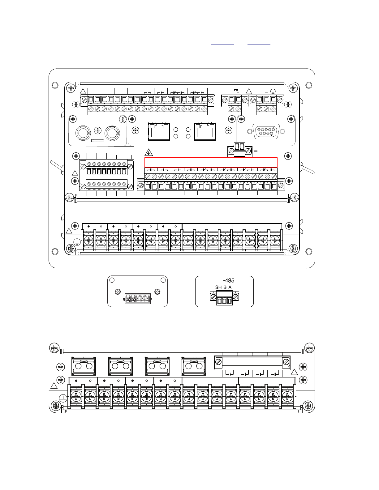
External Connections
The possible connections for the M‑7651A D‑PAC are shown in Figure 2 and Figure 3.
CAUTION:▲Any TB3 receptacle that is NOT GREEN indicates that a Low Voltage Power Supply is
installed in the unit.
TIA
ANALOG OUT
Port 1 Only
24V
AO1
AO2
COM
+ - + - +
IN 1 IN 2 IN 3 IN 4 OUT 1
PORT 1 PORT 4
IN 5 IN 6 IN7
IN9 IN 10 IN 11 IN12
OUT 2 OUT 3 OUT 4
OUT 7 OUT 8 OUT 9 OUT 10OUT 6OUT 5 OUT 12OUT 11
!
!
TB1 TB3
TB6
TB7
TB8
WARNING! CONTACT WITH TERMINALS
MAY CAUSE ELECTRIC SHOCK
IRIG B
TB4
P/S
+ -
12 2
13
1 1 3
1 1 2131322
1
2
1 1 313
12
12
12
12
12121212
12121212
IN8
AUX
I/O
SN:123456 IΦ=1A, Ig=50mA, (3)Vy=12Vmax, (3)Vz=12Vmax
+
CONTACT
RATINGS-
SEE MANUAL
!
12
+
TB2
RX TX
PORT 2
ETHERNET
PORT 3
RS-232
1
Vy
I1I2I31
g
IVy2Vy3Ny Vz1Vz2Vz3
2 3 4 5 6 7 8 9 10 11 12 13 14 15 16
Nz
1
Vy
I1I2I31
g
IVy2Vy3Ny Vz1Vz2Vz3
2 3 4 5 6 7 8 9 10 11 12 13 14 15 16
Nz
TB5
!
llllllIIlllllIl
Figure 2 M‑7651A External Connections (Typical conguration, other options are available)
OUT 13
2
1
OUT 14
2
1
OUT 15
2
1
OUT 16
2
1!!
1
Vy
I1I2I31
g
IVy2Vy3Ny Vz1Vz2Vz3
2 3 4 5 6 7 8 9 10 11 12 13 14 15 16
Nz
1
Vy
I1I2I31
g
IVy2Vy3Ny Vz1Vz2Vz3
2 3 4 5 6 7 8 9 10 11 12 13 14 15 16
Nz
RX TX RX TXRX TX RX TX
AF1 AF2 AF3 AF4 TB9
TB5
!
Figure 3 M‑7651A External Connections (Optional Arc Flash Module)

–5–
M‑7651A D‑PAC – Specification
†Select the greater of these accuracy values. For voltage accuracy specified, the range is (20 – 180 V).
PROTECTIVE FUNCTIONS
Device
Number Function
Setpoint
Ranges Increment Accuracy†
Sync Check
Reference Phase A/B/C – –
Undervoltage Permission
Dead Line/Dead Bus Yes/No – –
Dead Line/Live Bus Yes/No – –
Live Line/Dead Bus Yes/No – –
Live Line Minimum Voltage 0.0 to 200.0 V 0.1 V ± 0.2 V or ± 0.5%
Live Bus Minimum Voltage 0.0 to 200.0 V 0.1 V ± 0.2 V or ± 0.5%
Sync Check Permission
Max/Minimum Time Delay 0.01 to 600.00 s 0.01 s ±0.01 s or ± 1%
Minimum Voltage 10.0 to 300.0 V 0.01 V ± 0.2 V or ± 0.5%
Maximum Voltage 10.0 to 300.0 V 0.01 V ± 0.2 V or ± 0.5%
Angle Difference 0.00° to 90.00° 0.01° ± 0.3°
Magnitude Difference 0.00 to 300.00 V 0.01 V ± 0.2 V or ± 0.5%
Frequency Difference 0.00 to 5.00 Hz 0.01 Hz ± 0.02 Hz or ±2%
Undervoltage
Phase Undervoltage (#1 to #4 Steps)
Pickup 10.00 to 300.00 V 0.01 V ± 0.2 V or ± 0.5%
Definite Time 0.00 to 600.00 s 0.01 s ±0.01 s or ± 1%
Auto Restoration Enable/Disable
Phase-to-Phase Undervoltage
Pickup 10.00 to 300.00 V 0.01 V ± 0.2 V or ± 0.5%
Definite Time 0.00 to 600.00 s 0.01 s ±0.01 s or ± 1%
Vz1 Undervoltage
Pickup 10.00 to 300.00 V 0.01 V ± 0.2 V or ± 0.5%
Definite Time 0.00 to 600.00 s 0.01 s ±0.01 s or ± 1%
Bus Side Voltage Supervision
Bus Side Voltage Supervision
Minimum Closing Voltage 0.00 to 300.00 V 0.01 V ± 0.2 V or ± 0.5%
Supervision Time 0.00 to 600.00 s 0.01 s ±0.01 s or ± 1%
Directional Power (#1 to #4 Steps)
Pickup ‑3.00 to +3.00 PU 0.01 PU ± 0.02 PU or 3%
@ PF = 0.2 to 1.0
Definite Time 0.00 to 600.00 s 0.01 s ±0.01 s or ± 1%
Power Real/Reactive
Each directional power element can be set as overpower or underpower.
The per unit pickup is based on the nominal secondary VT voltage and CT current settings.
25
27
27
PP
27
Vz1
27B
32

–6–
M‑7651A D‑PAC – Specification
†Select the greater of these accuracy values. For voltage accuracy specified, the range is (20 – 180 V).
PROTECTIVE FUNCTIONS (cont.)
Device
Number Function
Setpoint
Ranges Increment Accuracy†
Loss of Field ‑ Dual‑zone Offset‑mho Characteristic (#1 to #2 Steps)
Circle Diameter
1 A CT 0.5 to 500.0 Ω0.1 Ω± 0.5 Ωor ± 5%
5 A CT 0.1 to 100.0 Ω0.1 Ω± 0.1 Ωor ± 5%
Offset
1 A CT ‑250.0 to 250.0 Ω0.1 Ω± 0.5 Ωor ± 5%
5 A CT ‑50.0 to 50.0 Ω0.1 Ω± 0.1 Ωor ± 5%
Time Delay 0.01 to 300.00 s 0.01 s ± 1 Cycle or ± 1%
Time Delay with Volt. Ctrl. 0.01 to 300.00 s 0.01 s ± 1 Cycle or ± 1%
Time delay with Voltage Control for each zone can be individually enabled.
Voltage Control 5 to 180 V 1 V ± 0.5 V or ± 0.5%
Directional Element 0° to 20° 1° –
40

–7–
M‑7651A D‑PAC – Specification
†Select the greater of these accuracy values. For voltage accuracy specified, the range is (20 – 180 V).
PROTECTIVE FUNCTIONS (cont.)
Device
Number Function
Setpoint
Ranges Increment Accuracy†
Negative Sequence Overcurrent (#1 to #5 Steps)
Definite Time
Pickup
1 A CT 0.02 to 20.00 A 0.01 A ± 0.02 A or ± 3%
5 A CT 0.10 to 100.00 A 0.01 A ± 0.1 A or ± 3%
Definite Time 0.00 to 600.00 s 0.01 s ± 0.01 s or ±1%
Inverse Time
Pickup
1 A CT 0.02 to 3.20 A 0.01 A ± 0.02 A or ± 3%
5 A CT 0.10 to 16.00 A 0.01 A ± 0.1 A or ± 3%
Electromechanical Reset Delay Yes/No
Reset Coefficient 0.001 to 30.000 s 0.001 s ± 0.01 s or ±1%
TCC Modifiers
Time Adder 0.00 to 30.00 s 0.01 s ± 0.01 s or ± 1%
Minimum Response
Time Adder 0.00 to 1.00 s 0.01 s ± 0.01 s or ± 1%
IEC Curves Family
(IEC 60255‑151)
Inverse, Very Inverse,
Extremely Inverse
Time Multiplier 0.05 to 1.00 0.01 ±2 cycles or ± 5%
IEEE Curves
(C37.112)
Moderately Inverse
Very Inverse
Extremely Inverse
Time Multiplier 0.10 to 25.00 0.01 ± 2 cycles or ±5%
US Curves Moderately Inverse
Standard Inverse
Very Inverse
Extremely Inverse
Short Time Inverse
Time Multiplier 0.05 to 15.00 0.01 ± 2 cycles or ±5%
Traditional Recloser
Curves
101; 102; 103; 104; 105; 106; 107; 111; 112; 113; 114; 115; 116; 117;
118; 119; 120; 121; 122; 131; 132; 133; 134; 135; 136; 137; 138; 139;
140; 141; 142; 151; 152; 161; 162; 163; 164; 165; 200; 201; 202
Time Multiplier 0.10 to 2.00 0.01 ± 2 cycles or ± 5%
Definite Time
Time Multiplier 0.10 to 100.00 0.01 ± 2 cycles or ±5%
46
DT
46
IT

–8–
M‑7651A D‑PAC – Specification
†Select the greater of these accuracy values. For voltage accuracy specified, the range is (20 – 180 V).
PROTECTIVE FUNCTIONS (cont.)
Device
Number Function
Setpoint
Ranges Increment Accuracy†
Negative Sequence Overvoltage
Pickup 0.00 to 300.00 V 0.01 V ± 0.2 V or ± 0.5%
Phase Current 0.00 to 600.00 s 0.01 s ± 0.01 s or ±1%
Breaker Failure
Pickup
Phase Current
1 A CT 0.02 to 2.00 A 0.01 A ± 0.02 A or ± 3%
5 A CT 0.10 to 10.00 A 0.01 A ± 0.1 A or ± 3%
Residual/ Ground (Sensitive Ground) Current
1 A CT 0.02 to 2.00 A 0.01 A ± 0.02 A or ± 3%
5 A CT 0.10 to 10.00 A 0.01 A ± 0.1 A or ± 3%
10 mA CT 0.001 to 0.160 A 0.001 A TBD
50 mA CT 0.005 to 0.800 A 0.001 A TBD
200 mA CT 0.020 to 3.200 A 0.001 A TBD
Time Delay 0.01 to 600.00 s 0.01 s ± 0.01 s or ±1%
Retrip Delay 0.01 to 600.00 s 0.01 s ± 0.01 s or ±1%
47
50
BF

–9–
M‑7651A D‑PAC – Specification
†Select the greater of these accuracy values. For voltage accuracy specified, the range is (20 – 180 V).
PROTECTIVE FUNCTIONS (cont.)
Device
Number Function
Setpoint
Ranges Increment Accuracy†
Instantaneous/Definite Time Overcurrent (#1 to #5 Steps)
Phase Instantaneous/Definite Time Overcurrent
Pickup
1 A CT 0.02 to 20.00 A 0.01 A ± 0.02 A or ± 3%
5 A CT 0.10 to 100.00 A 0.01 A ± 0.1 A or ± 3%
Definite Time 0.00 to 600.00 s 0.01 s ± 0.01 s or ±1%
High Current Lockout (#1 to #5 Steps)
Phase Enable/Disable
Reference Current
1 A CT 0.10 to 100.00 A 0.01 A ± 0.02 A or ± 3%
5 A CT 0.50 to 500.00 A 0.01 A ± 0.1 A or ± 3%
Definite Time 0.00 to 600.00 s 0.01 s ± 0.01 s or ±1%
Residual Instantaneous/Definite Time Overcurrent
Pickup
1 A CT 0.02 to 20.00 A 0.01 A ± 0.02 A or ± 3%
5 A CT 0.10 to 100.00 A 0.01 A ± 0.1 A or ± 3%
Definite Time 0.00 to 600.00 s 0.01 s ± 0.01 s or ±1%
High Current Lockout (#1 to #5 Steps) with "3I0" HCL Operating Current Reference
Residual/Ground Enable/Disable
Reference Current
1 A CT 0.03 to 100.00 A 0.01 A ± 0.02 A or ± 3%
5 A CT 0.15 to 500.00 A 0.01 A ± 0.02 A or ± 3%
Definite Time 0.00 to 600.00 s 0.01 s ± 0.01 s or ±1%
Ground Instantaneous/Definite Time Overcurrent
Pickup
1 A Gnd CT 0.02 to 20.00 A 0.01 A ± 0.02 A or ± 3%
5 A Gnd CT 0.10 to 100.00 A 0.01 A ± 0.1 A or ± 3%
Definite Time 0.00 to 600.00 s 0.01 s ± 0.01 s or ±1%
High Current Lockout (#1 to #5 Steps) with "G" HCL Operating Current Reference
Residual/Ground Enable/Disable
Reference Current
1 A Gnd CT 0.03 to 100.00 A 0.01 A ± 0.02 A or ± 3%
5 A Gnd CT 0.15 to 500.00 A 0.01 A ± 0.1 A or ± 3%
Definite Time 0.00 to 600.00 s 0.01 s ± 0.01 s or ±1%
50P
50
HCL
50N
50
HCL
50G
50
HCL

–10–
M‑7651A D‑PAC – Specification
†Select the greater of these accuracy values. For voltage accuracy specified, the range is (20 – 180 V).
PROTECTIVE FUNCTIONS (cont.)
Device
Number Function
Setpoint
Ranges Increment Accuracy†
Inverse Time Overcurrent (#1 to #5 Steps)
Phase Inverse Time Overcurrent with Voltage Control/Restraint
Pickup
1 A CT 0.02 to 3.20 A 0.01 A ± 0.02 A or ± 3%
5 A CT 0.10 to 16.00 A 0.01 A ± 0.1 A or ± 3%
Load Encroachment Logic Use/Do Not Use – –
Voltage Control or
Voltage Restraint 4.0 to 150.0 % 0.1 %
Residual Inverse Time Overcurrent
Pickup
1 A CT 0.02 to 3.20 A 0.01 A ± 0.02 A or ± 3%
5 A CT 0.10 to 16.00 A 0.01 A ± 0.1 A or ± 3%
Ground Inverse Time Overcurrent
Pickup
1 A Gnd CT 0.02 to 3.20 A 0.01 A ± 0.02 A or ± 3%
5 A Gnd CT 0.10 to 16.00 A 0.01 A ± 0.1 A or ± 3%
Electromechanical Reset Delay Yes/No
Reset Coefficient 0.001 to 30.000 s 0.001 s ± 0.01 s or ±1%
TCC Modifiers Time Adder 0.00 to 30.00 s 0.01 s ±0.01 s or ±1%
Minimum Response Time Adder 0.00 to 1.00 s 0.01 s ± 0.01 s or ±1%
IEC Curves Family
(IEC 60255‑151)
Inverse, Very Inverse
Extremely Inverse
Time Multiplier 0.05 to 1.00 0.01 ± 2 cycles or ± 5%
IEEE Curves
(C37.112)
Moderately Inverse
Very Inverse
Extremely Inverse
Time Multiplier 0.10 to 25.00 0.01 ± 2 cycles or ±5%
US Curves Moderately Inverse
Standard Inverse
Very Inverse
Extremely Inverse
Short Time Inverse
Time Multiplier 0.05 to 15.00 0.01 ± 2 cycles or ±5%
Traditional Recloser
Curves
101; 102; 103; 104; 105; 106; 107; 111; 112; 113; 114; 115; 116; 117;
118; 119; 120; 121; 122; 131; 132; 133; 134; 135; 136; 137; 138; 139;
140; 141; 142; 151; 152; 161; 162; 163; 164; 165; 200; 201; 202
Time Multiplier 0.10 to 2.00 0.01 ± 2 cycles or ± 5%
Definite Time
Time Multiplier 0.10 to 100.00 0.01 ± 2 cycles or ±5%
51P
51N
51G

–11–
M‑7651A D‑PAC – Specification
†Select the greater of these accuracy values. For voltage accuracy specified, the range is (20 – 180 V).
PROTECTIVE FUNCTIONS (cont.)
Device
Number Function
Setpoint
Ranges Increment Accuracy†
Overvoltage
Phase Overvoltage (#1 to #4 Steps)
Pickup 10.00 to 300.00 V 0.01 V ± 0.2 V or ± 0.5%
Definite Time 0.00 to 600.00 s 0.01 s ± 0.01 s or ±1%
Auto Restoration Enable/Disable
Peak Overvoltage
Pickup 100 to 150 % 1 % ± 3 %
Definite Time 0.01 to 140.00 s 0.01 s ± 0.05 s
Residual Overvoltage (#1 to #2 Steps)
Pickup 10.00 to 300.00 V 0.01 V ± 0.2 V or ± 0.5%
Definite Time 0.00 to 600.00 s 0.01 s ± 0.01 s or ±1%
Phase-to-Phase Overvoltage
Pickup 10.00 to 300.00 V 0.01 V ± 0.2 V or ± 0.5%
Definite Time 0.00 to 600.00 s 0.01 s ± 0.01 s or ±1%
Vz1 Overvoltage
Pickup 10.00 to 300.00 V 0.01 V ± 0.2 V or ± 0.5%
Definite Time 0.00 to 600.00 s 0.01 s ± 0.01 s or ±1%
VT Fuse‑Loss Detection
AVT fuse-loss condition is detected by using the positive and negative sequence components
of the voltages and currents.
Time Delay 0.03 to 600.00 s 0.01 s ± 0.01 s or ±1%
Three Phase VT
Fuse Loss Detection
Enable/Disable
59
59I
59N
59
PP
59
Vz1
60
FL

–12–
M‑7651A D‑PAC – Specification
†Select the greater of these accuracy values. For voltage accuracy specified, the range is (20 – 180 V).
PROTECTIVE FUNCTIONS (cont.)
Device
Number Function
Setpoint
Ranges Increment Accuracy†
Directional Overcurrent (#1 to #5 Steps)
Phase Directional Overcurrent
Operating Current Phase Current
Phase Polarization Voltage V1
Residual Directional Overcurrent
Operating Current 3IO
Phase Polarization Voltage Vz1, V1, V2, VO
Ground Directional Overcurrent
Operating Current Ig
Phase Polarization Voltage Vz1, V1, V2, VO
Negative Sequence Directional Overcurrent
Operating Current Negative Sequence Current
Phase Polarization Voltage V2
Enabled Direction No‑Direction/Directional
Minimum Polarization Voltage
(% of nominal voltage) 2.0 to 10.0 % 0.1% ± 3%
Action if below Trip/Block Trip
Maximum Sensitivity Angle 1 0° to 359° 1° ± 1°
Maximum Sensitivity Angle 2 5° to 90° 1° ± 1°
Time Delay Definite/Inverse – –
Definite Time:
Pickup
1 A CT/Gnd CT 0.05 to 20.00 A 0.01 A ± 0.02 A or ± 3%
5 A CT/Gnd CT 0.25 to 100.00 A 0.01 A ± 0.1 A or ± 3%
Delay 0.00 to 600.00 s 0.01 s ± 0.01 s or ± 1%
NOTE:QFunction 67 Inverse Time Delay Specifications continued on next page.
67P
67N
67G
67Q

–13–
M‑7651A D‑PAC – Specification
†Select the greater of these accuracy values. For voltage accuracy specified, the range is (20 – 180 V).
PROTECTIVE FUNCTIONS (cont.)
Device
Number Function
Setpoint
Ranges Increment Accuracy†
Directional Instantaneous/Definite Time Overcurrent (Cont.)
Inverse Time:
Pickup
1 A CT/Gnd CT 0.02 to 3.20 A 0.01 A ± 0.02 A or ± 3%
5 A CT/Gnd CT 0.10 to 16.00 A 0.01 A ± 0.1 A or ± 3%
Electromechanical Reset Delay Yes/No
Reset Coefficient 0.001 to 30.000 s 0.001 s ± 0.01 s or ±1%
TCC Modifiers
Time Adder 0.00 to 30.00 s 0.01 s ± 0.01 s or ± 1%
Minimum Response
Time Adder 0.00 to 1.00 s 0.01 s ± 0.01 s or ± 1%
IEC Curves Family
(IEC 60255‑151)
Inverse, Very Inverse,
Extremely Inverse
Time Multiplier 0.05 to 1.00 0.01 ± 2 cycles or ± 5%
IEEE Curves
(C37.112)
Moderately Inverse
Very Inverse
Extremely Inverse
Time Multiplier 0.10 to 25.00 0.01 ± 2 cycles or ±5%
US Curves Moderately Inverse
Standard Inverse
Very Inverse
Extremely Inverse
Short Time Inverse
Time Multiplier 0.05 to 15.00 0.01 ± 2 cycles or ±5%
Traditional Recloser
Curves
101; 102; 103; 104; 105; 106; 107; 111; 112; 113; 114; 115; 116; 117;
118; 119; 120; 121; 122; 131; 132; 133; 134; 135; 136; 137; 138; 139;
140; 141; 142; 151; 152; 161; 162; 163; 164; 165; 200; 201; 202
Time Multiplier 0.10 to 2.00 0.01 ± 2 cycles or ± 5%
Definite Time
Time Multiplier 0.10 to 100.00 0.01 ± 2 cycles or ±5%

–14–
M‑7651A D‑PAC – Specification
†Select the greater of these accuracy values. For voltage accuracy specified, the range is (20 – 180 V).
PROTECTIVE FUNCTIONS (cont.)
Device
Number Function
Setpoint
Ranges Increment Accuracy†
Frequency (#1 to #4 Steps)
Pickup 40.00 to 65.00 Hz 0.01 Hz ± 0.02 Hz
Definite Time 0.00 to 600.00 s 0.01 s ± 0.01 s or ±1%
Hysteresis 0.0 to 1.0 Hz 0.1 Hz
Undervoltage Block Enable/Disable
Minimum Voltage 1.00 to 180.00 V 0.01 V
Minimum Load Enable/Disable
1 A CT 0.00 to 40.00 A 0.01 A ± 0.02 A or ±3%
5 A CT 0.00 to 200.00 A 0.01 A ± 0.1 A or ±3%
The pickup accuracy applies at a range of 57 to 63 Hz. Beyond this range the accuracy is ±0.1 Hz.
Auto Restoration Enable/Disable
Rate of Change of Frequency (#1 to #2 Steps)
Pickup 0.20 to 5.00 Hz/s 0.01 Hz/s ± 0.02 Hz/s
Definite Time 0.00 to 2.00 s 0.01 s ± 0.01 s or ± 1%
Maximum Frequency 40.00 to 70.00 Hz 0.01 Hz
Minimum Current
1 A CT 0.00 to 20.00 A 0.01 A ± 0.02 A or ±3%
5 A CT 0.00 to 100.00 A 0.01 A ± 0.1 A or ±3%
Minimum Voltage 0.00 to 300.00 V 0.01 V
Pickup Cycle Number 3 to 15 1
Breaker Monitor
Pickup 1 to 60000 kA* Cycles 1 kA* Cycles ± 1 kA* Cycles
Time Delay 0.00 to 600.00 s 0.01 s ± 0.01 s or ± 1%
Breaker Open Arc Current Delay 0 to 2000 ms 1 ms
Arc Current Cycle 0 to 20 Cycles 1 Cycle
Preset Accumulators 0 to 60000 kA* Cycles 1 kA* Cycle
Timing Selection Method* I1.5T, IT or I2T
(*Timing Selection Method determines unit: kA, kA1.5 or kA2)
The Breaker Monitor feature calculates an estimate of the per-phase wear on the breaker contacts by measuring and
integrating the current through the breaker contacts as an arc.
The per-phase values are added to an accumulated total for each phase, and then compared to a user-programmed
threshold value. When the threshold is exceeded in any phase, the relay can set a programmable output contact.
The accumulated value for each phase can be displayed.
The Breaker Monitoring feature requires an initiating contact to begin accumulation, and the accumulation begins
after the set time delay.
81
81R
BM

–15–
M‑7651A D‑PAC – Specification
†Select the greater of these accuracy values. For voltage accuracy specified, the range is (20 – 180 V).
PROTECTIVE FUNCTIONS (cont.)
Device
Number Function
Setpoint
Ranges Increment Accuracy†
Inrush Harmonic Restraint
Inrush Harmonic Pickup 0.1 to 100% 0.1% ± 1%
Inrush Harmonic Dropout 0.1 to 100% 0.1% ± 1%
Inrush Active Time 0.01 to 600.00 s 0.01 s ± 0.01 s or ±1%
Trip/Close Circuit Monitoring
Time Delay 0.01 to 600.00 s 0.01 s ± 0.01 s or ±1%
Time Delay 0.01 to 600.00 s 0.01 s ± 0.01 s or ±1%
Trip Coil and Close Coil input voltages are limited to the specifications in Table 5.
Total Harmonic Distortion / Total Demand Distortion
Operating Quantity Current/Voltage
Limit 3.0 to 10.0 % 0.1% ± 2%
Time Delay 0.00 to 600.00 s 0.01 s ± 0.01 s or ±1%
Operating Quantity Current
Limit 3.0 to 10.0 % 0.1% ± 2%
Time Delay 0.00 to 600.00 s 0.01 s ± 0.05 s or ±1%
IHR
TCM
CCM
THD
TDD

–16–
M‑7651A D‑PAC – Specification
†Select the greater of these accuracy values. For voltage accuracy specified, the range is (20 – 180 V).
OPTIONAL PROTECTIVE FUNCTIONS (cont.)
Device
Number Function
Setpoint
Ranges Increment Accuracy†
Sensitive Ground Instantaneous/Definite Time Overcurrent (#1 to #5 Steps)
Sensitive Ground Pickup
10 mA Gnd CT 0.001 to 0.160 A 0.001 A (TBD)
50 mA Gnd CT 0.001 to 0.800 A 0.001 A 0.0015 A or ± 3%
200 mA Gnd CT 0.020 to 2.500 A 0.001 A (TBD)
Definite Time 0.00 to 600.00 s 0.01 s ±0.01 s or ±1%
Replaces Standard 50G Ground
High Current Lockout (#1 to #5 Steps) with "G" HCL Operating Current Reference
Residual/Ground Enable/Disable – –
Reference Current
10 mA Gnd CT 0.001 to 0.160 A 0.001 A (TBD)
50 mA Gnd CT 0.001 to 0.800 A 0.001 A 0.0015 A or ± 3%
200 mA Gnd CT 0.020 to 2.500 A 0.001 A (TBD)
Definite Time 0.00 to 600.00 s 0.01 s ±0.01 s or ±1%
Sensitive Ground Inverse Time Overcurrent (#1 to #5 Steps)
Sensitive Ground Pickup
10 mA Gnd CT 0.001 to 0.160 A 0.001 A (TBD)
50 mA Gnd CT 0.001 to 0.800 A 0.001 A 0.0015 A or ±3%
200 mA Gnd CT 0.020 to 2.500 A 0.001 A (TBD)
Electromechanical Reset Delay Yes/No
Reset Coefficient 0.001 to 30.000 s 0.001 s ± 0.01 s or ±1%
TCC Modifiers
Time Adder 0.00 to 30.00 s 0.01 s ± 0.01 s or ± 1%
Minimum Response Time Adder 0.00 to 1.00 s 0.01 s ± 0.01 s or ±1%
IEC Curves Family (IEC 60255‑151) Inverse, Very Inverse, Extremely Inverse
Time Multiplier 0.05 to 1.00 0.01 ± 2 cycles or ± 5%
IEEE Curves (C37.112) Moderately Inverse, Very Inverse, Extremely Inverse
Time Multiplier 0.10 to 25.00 0.01 ± 2 cycles or ±5%
US Curves Moderately Inverse, Standard Inverse, Very Inverse,
Extremely Inverse, Short Time Inverse
Time Multiplier 0.05 to 15.00 0.01 ± 2 cycles or ±5%
Traditional Recloser
Curves
101; 102; 103; 104; 105; 106; 107; 111; 112; 113; 114; 115; 116; 117;
118; 119; 120; 121; 122; 131; 132; 133; 134; 135; 136; 137; 138; 139;
140; 141; 142; 151; 152; 161; 162; 163; 164; 165; 200; 201; 202
Time Multiplier 0.10 to 2.00 0.01 ± 2 cycles or ± 5%
Definite Time
Time Multiplier 0.10 to 100.00 0.01 ± 2 cycles or ±5%
Replaces Standard 51G Ground
50
GS
50
HCL
51
GS

–17–
M‑7651A D‑PAC – Specification
†Select the greater of these accuracy values. For voltage accuracy specified, the range is (20 – 180 V).
OPTIONAL PROTECTIVE FUNCTIONS (cont.)
Device
Number Function
Setpoint
Ranges Increment Accuracy†
Sensitive Ground Inverse Time Overcurrent (#1 to #5 Steps)
Phase Polarization Voltage Vz1, V1, V2, VO– –
Enabled Direction No‑Direction/Directional – –
Minimum Polarization Voltage
(% of nominal voltage) 2.0 to 10.0 % 0.1% ± 3%
Action if below Trip/Block Trip – –
Maximum Sensitivity Angle 1 0° to 359° 1° ± 4°
Maximum Sensitivity Angle 2 5° to 90° 1° ± 4°
Time Delay Definite/Inverse – –
Definite Time:
Pickup 10 mA Gnd CT 0.001 to 0.160 A 0.001 A (TBD)
Pickup 50 mA Gnd CT 0.005 to 0.800 A 0.001 A 0.0015 A or ± 3%
Pickup 200 mA Gnd CT 0.020 to 2.500 A 0.001 A (TBD)
Delay 0.00 to 600.00 s 0.01 s ±0.01 s or ± 1%
Inverse Time:
Electromechanical Reset Delay Yes/No
Reset Coefficient 0.001 to 30.000 s 0.001 s ±0.01 s or ±1%
TCC Modifiers
Time Adder 0.00 to 30.00 s 0.01 s ±0.01 s or ±1%
Minimum Response Time Adder 0.00 to 1.00 s 0.01 s ± 0.01 s or ± 1%
IEC Curves Family
(IEC 60255‑151)
Inverse, Very Inverse,
Extremely Inverse
Time Multiplier 0.05 to 1.00 0.01 ± 2 cycles or ± 5%
IEEE Curves (C37.112) Moderately Inverse, Very Inverse,
Extremely Inverse
Time Multiplier 0.10 to 25.00 0.01 ±2 cycles or ± 5%
US Curves Moderately Inverse, Standard Inverse, Very Inverse,
Extremely Inverse, Short Time Inverse
Time Multiplier 0.05 to 15.00 0.01 ±2 cycles or ± 5%
Traditional Recloser
Curves
101; 102; 103; 104; 105; 106; 107; 111; 112; 113; 114; 115; 116; 117;
118; 119; 120; 121; 122; 131; 132; 133; 134; 135; 136; 137; 138; 139;
140; 141; 142; 151; 152; 161; 162; 163; 164; 165; 200; 201; 202
Time Multiplier 0.10 to 2.00 0.01 ± 2 cycles or ± 5%
Definite Time
Time Multiplier 0.10 to 100.00 0.01 ± 2 cycles or ±5%
Replaces Standard 67G Ground
67
GS

–18–
M‑7651A D‑PAC – Specification
†Select the greater of these accuracy values. For voltage accuracy specified, the range is (20 – 180 V).
OPTIONAL PROTECTIVE FUNCTIONS (cont.)
Device
Number Function
Setpoint
Ranges Increment Accuracy†
Recloser Relay
Three-Phase Ganged Operation:
Ground Precedence Yes/No
Sequence Coordination Active
For Trips None/1/2/3 – –
Maximum Number of Phase Trips 1/2/3/4/5 1 –
Maximum Number of Ground/
Residual Trips
1/2/3/4/5 1 –
Reset Time after Auto Reclose 1 to 1800 s 1 s ± 0.01 s or ± 1%
Reset Time from Lockout 0 to 1800 s 1 s ± 0.01 s or ± 1%
Reclose #1, #2, #3, #4
Time Delay for Phase Fault 0.01 to 600.00 s 0.01 s ± 0.01 s or ± 1%
Time Delay for Ground Fault 0.01 to 600.00 s 0.01 s ± 0.01 s or ± 1%
Arc Flash
Arc Light:
Definite Time 0.2 to 16.0 ms 0.1 ms 0.05 ms
Time Delay 0.2 to 16.0 ms 0.1 ms 0.13 ms (60 Hz)
0.16 ms (50 Hz)
Sensitivity 0 to 100%
(Min/Max based on
calibration results)
1% –
Overcurrent:
Peak Phase Pickup
1 A CT 0.02 to 20.00 A 0.01 A ± 0.02 A or ±3%
5 A CT 0.10 to 100.00 A 0.01 A ± 0.1 A or ±3%
Peak Neutral Pickup
1 A CT 0.02 to 20.00 A 0.01 A ± 0.02 A or ±3%
5 A CT 0.10 to 100.00 A 0.01 A ± 0.1 A or ±3%
10 mA CT 0.001 to 0.160 A 0.001 A TBD
50 mA CT 0.001 to 0.800 A 0.001 A 0.0015 A or ± 3%
200 mA CT 0.020 to 2.500 A 0.001 A TBD
Overcurrent Definite Time 0.2 to 16.0 ms 0.1 ms 0.13 ms (60 Hz)
0.16 ms (50 Hz)
Overcurrent Time Delay 0.2 to 16.0 ms 0.1 ms 0.13 ms (60 Hz)
0.16 ms (50 Hz)
79
AF
Table of contents
Other BECKWITH ELECTRIC Industrial Equipment manuals

Popular Industrial Equipment manuals by other brands


Pepperl+Fuchs
Pepperl+Fuchs LS68 DA-F2 Series manual

Nordco
Nordco C Installation, operation and maintenance manual

OmniOn Power
OmniOn Power G391 quick start guide

Siemens
Siemens 3RT7014 Series operating instructions

Siemens
Siemens SIRIUS 3TK2810-1BA4 Series operating instructions

BOCI
BOCI BLT481 product manual