5
Operation
CPC III Manual
(PPPT)
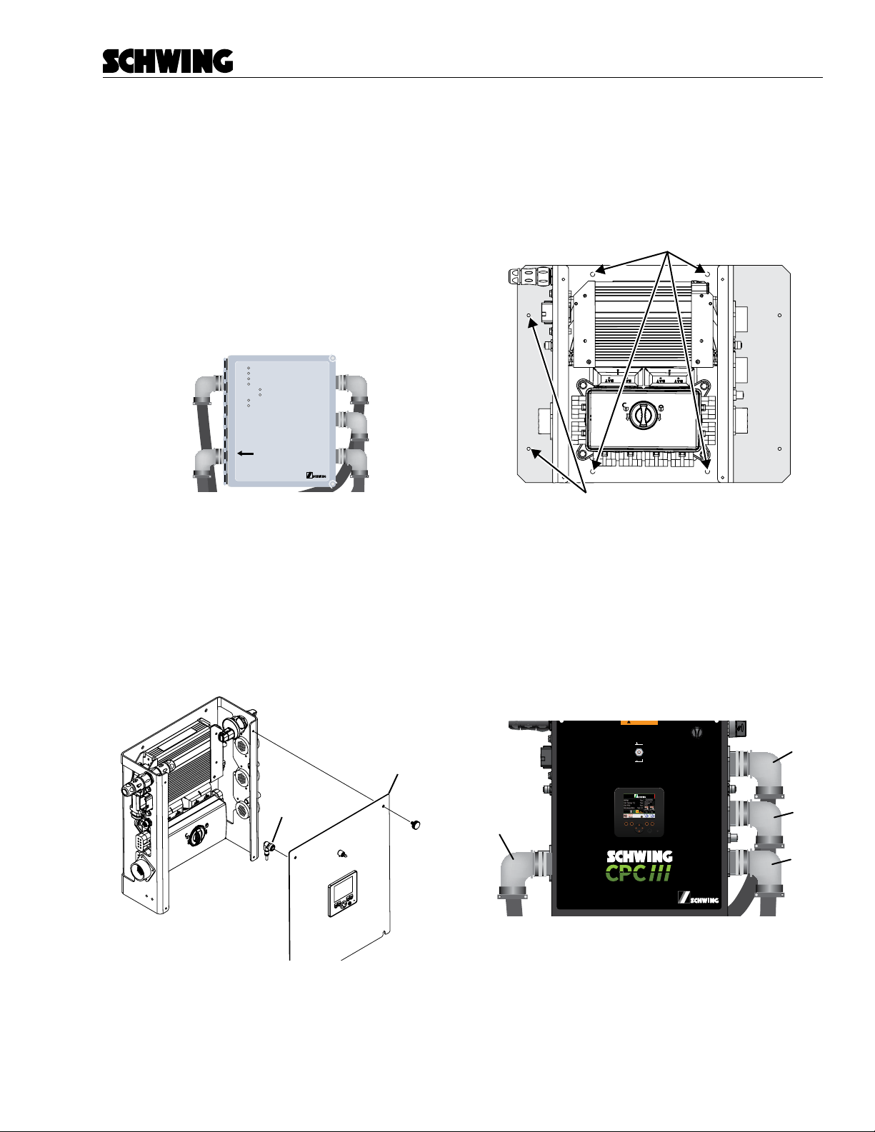
I/O Harness
(PIOE)
Oil Temperature
(POTS)
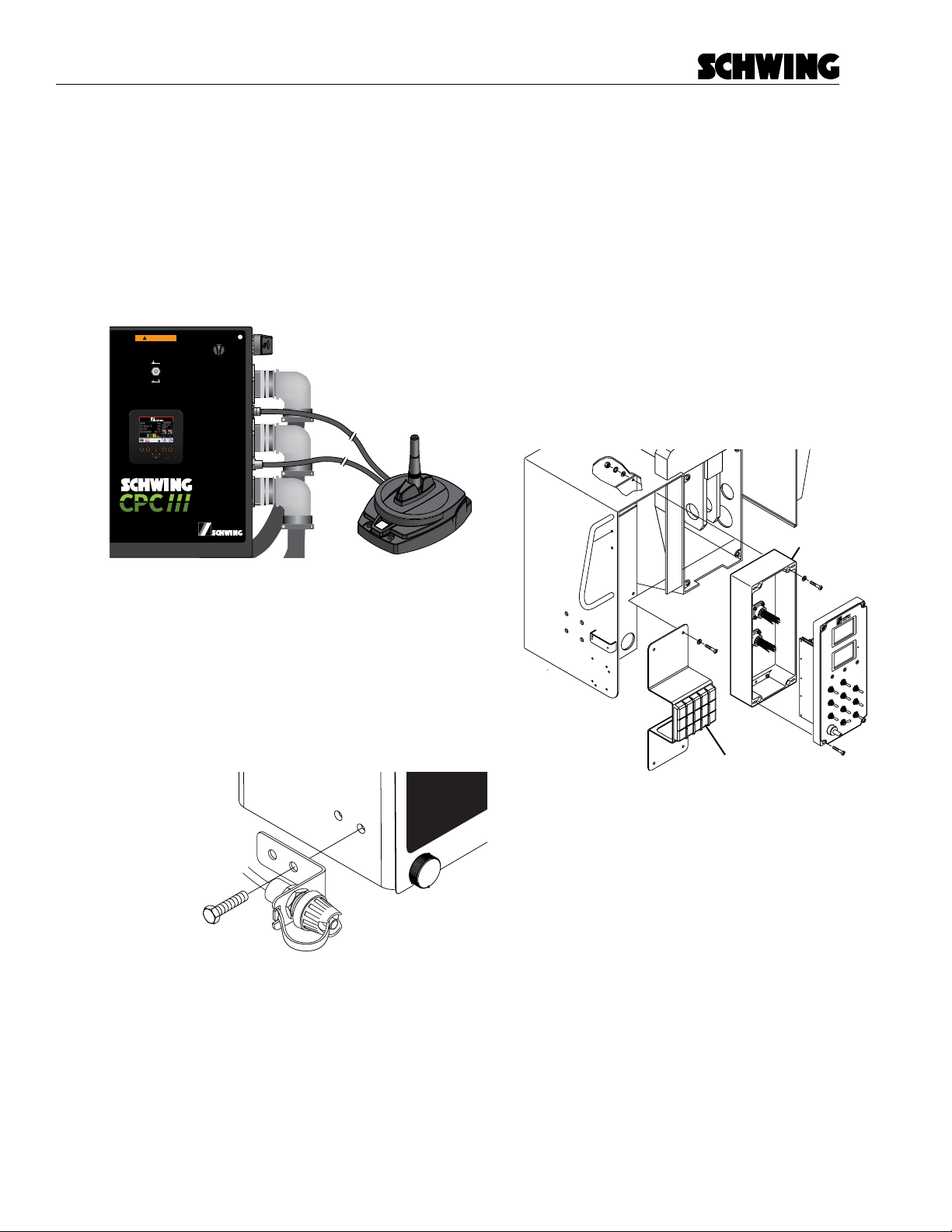
- Plug in the connector labeled “Keypad” to the
Rear Keypad.
- If Installed: Concrete Pressure Sensor: Plug in
the M12 connector to the Concrete Pressure
Sensor.
- One of the connectors you disconnected from
the Rear Control Panel will plug into the I/O-E
Harness (PIOC).
Note: On the early C32 rear panels, only one
connector was used. I this case PIOC will not be
used.
6. Connect the supplied connector jumper to the
remaining connector from the old Rear Control
Panel. (Item 60 on BOM 98458427)
Clean up the harnesses and nish securing all equip-
ment. (Item 270 on BOM 98458427)
Initial Setup
1. Turn on PTO but do not run the engine.
2. Turn on the Maintenance Switch. Inspect F9 fuse
in the PDM. If F9 fuse blows (or is already blown)
then nd the Quick Disconnect (PQD1) on the
harness located next to Cable C and disconnect
it. Tape the connector ends.
- Reset the circuit breaker by cycling the power.
- Turn o the maintenance switch.
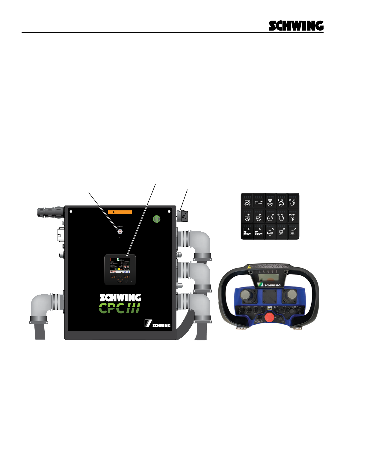
Maintenance Switch
(PMS)
OFF
ON
Figure 8
Maintenance switch
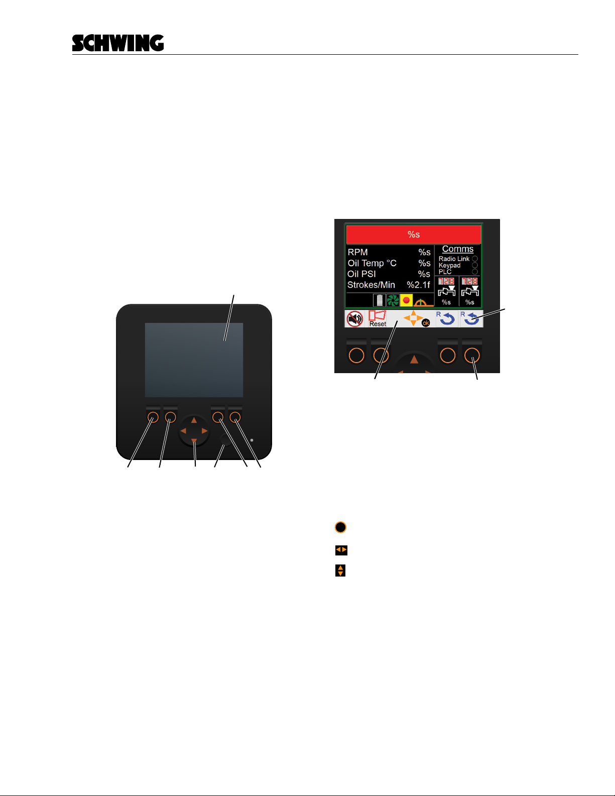
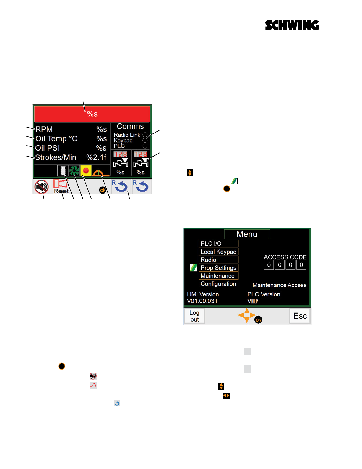
3. Ignore all error messages for now. Go to the
Conguration screen using the system password
and adjust the system settings.
Screen Settings
1Channel E-stop Only select this option if the system you are
replacing had single channel E-Stops.
CPC2 Compatible Only select this option if the system you are
replacing was a CPC2 type machine.
Stroke Counter Select if the unit has a Stroke Counter.
Oil Pressure Sensor Select if the unit has an Oil Pressure Sensor
Agitator Disable Select this option if the unit does NOT have
an electrically controlled agitator.
Boom Horn Disable Select this if the unit does NOT have a
Boom Horn.
Boom Type Choose the Boom Type: 3 Section, 4 Sec-
tion, etc.
Max Engine RPM Max engine RPMs allowed.
Important Notes
1. On some units the Agitator Forward and Reverse
buttons may be backwards. If yours is backwards,
swap the agitator forward and reverse connec-
tors at the valve.
2. All agitator forward and reverse buttons will need
to be removed from the unit as they will no longer
work. Use the rear keypad or radio remote.
3. If fuse F9 blows go to the initial setup instructions.
Fully test the system and Teach the boom using the fac-
tory login.