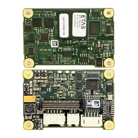
Becom CM-BF537 Instructions for use

CM-BF537
Hardware User Manual
Version 10

© BECOM Systems 2020
Hardware User Manual - CM-BF537
Last change: 26. March 2019/Version 10
2| 33
BECOM Systems GmbH
Gutheil-Schoder-Gasse 17
1230 Wien
AUSTRIA
office.systems@becom-group.com
http://systems.becom-group.com
CM-BF537 –Hardware User Manual
Template No.: 900-520 Rev A
Publication date: February 4, 2020
Subject to change without notice. Errors excepted.
This document is protected by copyright. All rights reserved. No part of this document may be reproduced or
transmitted for any purpose in any form or by any means, electronically or mechanically, without expressly
written permission by
BECOM Systems.
Windows is a registered trademark of Microsoft.

© BECOM Systems 2020
Hardware User Manual - CM-BF537
Last change: 26. March 2019/Version 10
3| 33
Table of Contents
1Introduction...............................................................................................................................................................................................................................6
1.1 Overview................................................................................................................................................................................................................................6
1.2 Key Features..................................................................................................................................................................................................................7
1.3 Applications.................................................................................................................................................................................................................. 8
2General Description ............................................................................................................................................................................................................9
2.1 Functional Description .........................................................................................................................................................................................9
2.2 Boot Mode......................................................................................................................................................................................................................9
2.3 Memory Map ..............................................................................................................................................................................................................10
2.3.1 Core Module Memory...................................................................................................................................................................................10
2.3.2 Board modifications........................................................................................................................................................................................10
2.3.3 Externally Addressable Memory (on connector)....................................................................................................................11
3Specifications.........................................................................................................................................................................................................................12
3.1 Electrical Specifications.....................................................................................................................................................................................12
3.1.1 Maximum Ratings .............................................................................................................................................................................................12
3.1.2 Operating Conditions....................................................................................................................................................................................12
3.1.3 ESD Sensitivity.....................................................................................................................................................................................................13
4Connector Description...................................................................................................................................................................................................14
4.1 Connector X1...............................................................................................................................................................................................................14
4.2 Connector X2..............................................................................................................................................................................................................16
5Application Information................................................................................................................................................................................................18
5.1 Supply Voltage Decoupling ...........................................................................................................................................................................18
5.2 Reset circuit .................................................................................................................................................................................................................18
5.3 Application Example Schematics..............................................................................................................................................................19
5.3.1 RJ45 schematic....................................................................................................................................................................................................19
5.4 Sample Schematic................................................................................................................................................................................................ 20
5.5 Stand-alone Ethernet based MPEG webcam..................................................................................................................................21
6Mechanical Outline ..........................................................................................................................................................................................................23
6.1 Top View........................................................................................................................................................................................................................23
6.2 Bottom View..............................................................................................................................................................................................................24

© BECOM Systems 2020
Hardware User Manual - CM-BF537
Last change: 26. March 2019/Version 10
4| 33
6.3 Side View ......................................................................................................................................................................................................................24
6.4 Footprint........................................................................................................................................................................................................................25
6.5 Connectors ..................................................................................................................................................................................................................25
7Support.......................................................................................................................................................................................................................................26
7.1 General Support......................................................................................................................................................................................................26
7.2 Board Support Packages..................................................................................................................................................................................26
7.3 Blackfin® Software Support ..........................................................................................................................................................................26
7.3.1 BLACKSheep® OS .............................................................................................................................................................................................26
7.3.2 LabVIEW...................................................................................................................................................................................................................26
7.3.3 uClinux.......................................................................................................................................................................................................................26
7.4 Blackfin®Design Services.................................................................................................................................................................................26
7.4.1 Upcoming Products and Software Releases ............................................................................................................................26
8Ordering Information......................................................................................................................................................................................................27
9Dependability........................................................................................................................................................................................................................28
9.1 MTBF .................................................................................................................................................................................................................................28
10 Product History....................................................................................................................................................................................................................29
10.1 Version Information.............................................................................................................................................................................................29
10.1.1 CM-BF537-C-C-Q25S32F4 (CM-BF537E)........................................................................................................................................29
10.1.2 CM-BF537-C-I-Q25S32F4 (CM-BF537E-I) ................................................................................................................................29
10.1.3 CM-BF537-C-C-Q25S64F4 (CM-BF537E-64SD)..................................................................................................................30
10.2 Anomalies.....................................................................................................................................................................................................................30
11 Document Revision History........................................................................................................................................................................................31
12 List of Abbreviations.......................................................................................................................................................................................................32
AList of Figures and Tables ...........................................................................................................................................................................................33

© BECOM Systems 2020
Hardware User Manual - CM-BF537
Last change: 26. March 2019/Version 10
5| 33
© BECOM Systems GmbH 2020
All Rights Reserved.
The information herein is given to describe certain components and shall not be considered as a guarantee of
characteristics.
Terms of delivery and rights of technical change reserved.
We hereby disclaim any warranties, including but not limited to warranties of non-infringement, regarding
circuits, descriptions and charts stated herein.
BECOM Systems makes and you receive no warranties or conditions, express, implied, statutory or in any
communication with you. BECOM Systems specifically disclaims any implied warranty of merchantability or fitness
for a particular purpose.
BECOM Systems takes no liability for any damages and errors causing of the usage of this board. The user of this
board is responsible by himself for the functionality of his application. He is allowed to use the board only if he
has the qualification. More information is found in the General Terms and Conditions (AGB).
Information
For further information on technology, delivery terms and conditions and prices please contact BECOM Systems
www.becom-group.com

© BECOM Systems 2020
Hardware User Manual - CM-BF537
Last change: 26. March 2019/Version 10
6| 33
1Introduction
The Core-Module CM-BF537 is characterized by its field of application, performance and configuration possibility.
The module integrates processor, RAM, flash, external peripheral controllers and power supply at a size of
31.5x36.5mm! It is based at the high performance ADSP-BF537 from Analog Devices. The Core-Module is designed
for commercial and industrial usage (depending on temperature range). It addresses up to 64MByte SDRAM via its
16bit wide SDRAM bus, has an onboard NOR-flash of 4MByte and offers a CAN interface. In addition, there is an
extra Ethernet physical transceiver (10/100Mbit) onboard.
1.1 Overview
The current hardware version (see Version Information) of Core Module CM-BF537-C-C-Q25S32F4 (CM-BF537E)
consists of the following components. Parts of mounting options of CM-BF537 are listed in addition.
Up to
64MByte
SDRam
60 Pin Expansion Connector A
Up to
8MByte
Flash
ADSP
BF537
up to
600 MHz
Dynamic
Core Voltage
Control
60 Pin Expansion Connector B
Low Voltage
Reset Ethernet
Physical
Figure 1-1: Main components of the CM-BF537 Core Module
•Analog Devices Blackfin Processor BF537
oIndustrial version (see chapter 8.1)
▪ADSP-BF537SBBCZ-5A (-40° - 85°C)
oCommercial version (see chapter 8.1)
▪ADSP-BF537SKBCZ-6AV (0° - 70°C)
•SDRAM
oUU32MByte SDRAMUU Version (see chapter 8.1)
▪SDRAM Clock up to 133MHz
▪MT48LC16M16A2BG-7 (16Mx16, 256Mbit at 3.3 V)
oUU64MByte SDRAMUU Version (see chapter 8.1)

© BECOM Systems 2020
Hardware User Manual - CM-BF537
Last change: 26. March 2019/Version 10
7| 33
▪SDRAM Clock up to 143MHz
▪IS42S16320B-7BL (8M x16x4, 512Mbit at 3.3 V)
•4 MByte of Addressable Flash
oPF48F2000P0ZBQ0 (4Mx16 32Mbit at 3.3 V; default only 4MByte addressable)
oAdditional flash memory can be connected through the expansion board as parallel flash using
asynchronous chip select lines or as an SPI flash.
•Ethernet Physical Transceiver
oMicrochip KSZ8041NLI
•Low Voltage Reset Circuit
oResets module if power supply goes below 2.93 V for at least 140 ms
•Dynamic Core Voltage Control
oCore voltage is adjustable by setting software registers on the Blackfin processor
oCore voltage range: 0.8 –1.32V
•Expansion Connector A
oData Bus
oAddress Bus
oControl Signals
oPower Supply
oEthernet Pins
•Expansion Connector B
oSPORT0
oJTAG
oUART0/UART1
oCAN
oTWI (I²C compatible)
oSPI
oPPI (Parallel Port Interface)
oGPIO’s
1.2 Key Features
•The CM-BF537 is very compact and measures only 36.5x31.5mm
•Allows quick prototyping of product that comes very close to the final design
•Reduces development costs, faster time to market
•Very cost effective for small and medium volumes

© BECOM Systems 2020
Hardware User Manual - CM-BF537
Last change: 26. March 2019/Version 10
8| 33
1.3 Applications
•Robotics
•Video security
•Video surveillance
•Industrial distributed control
•Industrial factory automation
•Remote monitoring devices
•Point-of-sale terminals
•VoIP
•Biometrics/security
•Instrumentation
•Medical appliances
•Consumer appliances

© BECOM Systems 2020
Hardware User Manual - CM-BF537
Last change: 26. March 2019/Version 10
9| 33
2General Description
2.1 Functional Description
Up to
64MByte
SDRam
4MByte
Flash
ADSP
BF537
up to
600MHz
Dynamic
Core Voltage
Control
Low Voltage
Reset
20 Bit Address Bus
16 Bit Data Bus
Ethernet
Physical
Clock
Mem. Control, Boot Mode, JTAG, Ethernet
Data & Address Bus
Clock-out PPI, SPORT0, UART1, UART2, SPI, TWI, CAN, GPIO
3V3 Power , Reset
Figure 2-1: Detailed block diagram
Figure 2-1 shows a detailed block diagram of the CM-BF537. Other than the SDRAM control pins the CM-BF537 has
all other pins of the Blackfin processor on its two main 60 pin connectors.
A special feature of the Core Module CM-BF537 is the on-board physical Ethernet transceiver from Microchip
(KSZ8041NLI).
Dynamic voltage control allows reducing power consumption to a minimum adjusting the core voltage and the
clock frequency dynamically in accordance to the required processing power. A low voltage reset circuit
guarantees a power on reset and resets the system when the input voltage drops below 2.93V.
2.2 Boot Mode
By default, the boot mode = 000 (BMODE2 = low, BMODE1 = low, BMODE0 = low). All BMODE pins have internal
pull-down resistors.
Connect BMODE0 to VCC and leave BMODE1, BMODE2 pins open for boot mode 001 equals to 8- or 16-bit
PROM/FLASH boot mode, this is the default boot mode of BLACKSheep® OS. See Blackfin Datasheets or
Eval/DevBoard manuals for more details.

© BECOM Systems 2020
Hardware User Manual - CM-BF537
Last change: 26. March 2019/Version 10
10 | 33
2.3 Memory Map
2.3.1 Core Module Memory
Memory Type
Start Address
End Address
Size
Comment
FLASH Bank0
(PF4 Flag low)
0x20000000
0x201FFFFF
2MB
1/8 of 16MB NOR Flash,
IS29GL256-70DLEB
FLASH Bank1
(PF4 Flag high)
0x20000000
0x201FFFFF
2MB
1/8 of 16MB NOR Flash,
IS29GL256-70DLEB
FLASH Bank2
(PF5 Flag low) 1)
0x20000000
0x201FFFFF
2MB
1/8 of 16MB NOR Flash,
IS29GL256-70DLEB
FLASH Bank3
(PF5 Flag high) 1)
0x20000000
0x201FFFFF
2MB
1/8 of 16MB NOR Flash,
IS29GL256-70DLEB
SD-RAM32
0x00000000
0x01FFFFFF
32MB
16Bit Bus, Micron
IS29GL256-70DLEB
SD-RAM64
0x00000000
0x1FFFFFFF
64MB
16Bit Bus, ISSI
IS42S16320B-7BL
Table 2-1: Memory map
Note 1) not usable in default configuration. This PF5 is routed to the connector (see 2.3.2).
The maximum amount of addressable memory by a single asynchronous memory bank is 2MByte. In order to be
able to use more than 2MByte on a single bank 2 GPIOs are used to select which 2MB section of flash is active in
the memory window of the Blackfin processor. This frees up the remaining banks for the user.
The maximum amount of memory addressable by the processor is 8MByte.
2.3.2 Board modifications
By default, PF5 is routed to the connector of the Core Module. Nevertheless, this pin can be used to select
bank2/3 of the flash memory. To realize this, the 0 Ω resistor R18 must be removed and soldered to resistor R19
position on the Core Module. In this case PF5 is routed to the flash memory instead to the connector!
Figure 2-2: PF4 and PF5 routing

© BECOM Systems 2020
Hardware User Manual - CM-BF537
Last change: 26. March 2019/Version 10
11 | 33
Figure 2-3: Assembly drawing top view
Warning
BECOM Systems cannot take responsibility for customer-modified boards. If you need
modifications, please request a quote at office.systems@becom-group.com.
2.3.3 Externally Addressable Memory (on connector)
The Blackfins External Bus Interface (EBI) allows connecting devices via an asynchronous memory interface.
AMS Line
Start Address
End Address
Max. Size
nAMS2
0x20200000
0x202FFFFF
1MB
nAMS3
0x20300000
0x203FFFFF
1MB
Table 2-2: Externally addressable memory

© BECOM Systems 2020
Hardware User Manual - CM-BF537
Last change: 26. March 2019/Version 10
12 | 33
3Specifications
3.1 Electrical Specifications
3.1.1 Maximum Ratings
Stressing the device above the rating listed in the absolute maximum ratings table may cause permanent damage
to the device. These are stress ratings only. Operation of the device at these or any other conditions greater than
those indicated in the operating sections of this specification is not implied. Exposure to absolute maximum
rating conditions for extended periods may affect device reliability.
Symbol
Parameter
Min
Max
Unit
VIO
Input or output voltage
-0.5
3.8
V
VIN
Input supply voltage
3.0
3.6
V
IOH /IOL
Current per pin
0
10
mA
TAMBI
Ambient temperature (industrial)
-40
85
°C
TAMBC
Ambient temperature (commercial)
0
70
°C
TSTO
Storage temperature
-55
150
°C
TSLD
Solder temperature for 10 seconds
260
°C
φAMB
Relative ambient humidity
90
%
Table 3-1: Absolute maximum ratings
3.1.2 Operating Conditions
Symbol
Parameter
Min
Typical
Max
Unit
VIN
Input supply voltage
3.0
3.3
3.6
V
I3V33)
3.3V current
-
350
-
mA
VOH
High level output voltage
2.8
-
-
V
VOL
Low level output voltage
-
-
0.5
V
IIH
IO input current
-
-
10
µA
IOZ
Three state leakage current
-
-
10
µA
IDEEPSLEEP
VIN current in deep sleep mode
-
16
-
mA
ISLEEP
VIN current in sleep mode
-
19.5
-
mA
IIDLE
VIN current in idle mode
-
24
-
mA
ITYP
VIN current in with core running at 400 MHz
-
138
-
mA
IHIBERNATE1)
VIN current in hibernate state at 400 MHz
-
-
70
mA
IRTC
VRTC current
-
20
-
µA
fCCLKC
Core clock frequency (commercial grade)
100
-
600
MHz
fCCLKI
Core clock frequency (industrial grade)
100
-
500
MHz
Table 3-2: Electrical characteristics

© BECOM Systems 2020
Hardware User Manual - CM-BF537
Last change: 26. March 2019/Version 10
13 | 33
Note 1) VDDINT=1.10V @ TJ=25°C
Note 3) Average load @ 25°C ambient temperature
3.1.3 ESD Sensitivity
ESD (electrostatic discharge) sensitive device. Charged devices and circuit boards can
discharge without detection. Although this product features patented or proprietary
protection circuitry, damage may occur on devices subjected to high energy ESD. Therefore,
proper ESD precautions should be taken to avoid performance degradation or loss of
functionality.

© BECOM Systems 2020
Hardware User Manual - CM-BF537
Last change: 26. March 2019/Version 10
14 | 33
4Connector Description
4.1 Connector X1
Pin No.
Signal Name
Type
Function
1
RSCLK0 / TACLK2
I/O
SPORT
2
DR0PRI / TACLK4
I
SPORT
3
TSCLK0 / TACLK1
I/O
SPORT
4
DT0PRI / SSEL2
O
SPORT
5
CLKBUF
O
25MHz buffered clock output
6
SDA
I/O
I²C
7
PF4 / TMR5 / SSEL6: MO1 3)
NC: MO2, MO3 3)
I/O
GPIO / Timer / SPI
or Not connected
8
PF5 / TMR4 / SSEL5: MO1, MO2 1) 3)
NC: MO3 3)
I/O
GPIO / Timer / SPI
or Not connected
9
Vin 3V3
PWR
3V3 +-10% 500mA peak for supply
10
Vin 3V3
PWR
3V3 +-10% 500mA peak for supply
11
PG0 / PPI1D0
I/O
GPIO / PPI data
12
PG2 / PPI1D2
I/O
GPIO / PPI data
13
PG4 / PPI1D4
I/O
GPIO / PPI data
14
PG6 / PPI1D6
I/O
GPIO / PPI data
15
PG8 / PPI1D8 / DR1SEC
I/O
GPIO / PPI data / SPORT
16
PG10 / PPI1D10 / RSCLK1
I/O
GPIO / PPI data / SPORT
17
PG12 / PPI1D12 / DR1PRI
I/O
GPIO / PPI data / SPORT
18
PG14 / PPI1D14 / TFS1
I/O
GPIO / PPI data / SPORT
19
PPI1SY3 / PF7 / TMR2
I/O
GPIO / PPI sync / Timer
20
PPI1SY1 / PF9 / TMR0 1)
I/O
GPIO / PPI sync / Timer
21
PPI1SY1 / PF9 / TMR0 1)
I/O
GPIO / PPI sync / Timer
22
PF3 / Rx1 / TMR6 / TACI6
I/O
GPIO /Timer
23
PF1 / DMAR1 / TACI1 / Rx0
I/O
GPIO / UART
24
PF11 / MOSI
I/O
GPIO / SPI
25
PF13 / SCK
I/O
GPIO / SPI
26
BMODE0 2)
I - 10k pull down
Boot mode
27
GND
PWR
Power
28
TCK 2)
I - 10k pull up
JTAG
29
TDI 2)
I - 10k pull up
JTAG
30
TRST 2)
I - 4k7 pull down
JTAG
31
EMU
O
JTAG
32
TMS 2)
I - 10k pull up
JTAG
33
TDO
O
JTAG
34
BMODE2 2)
I - 10k pull down
Boot mode

© BECOM Systems 2020
Hardware User Manual - CM-BF537
Last change: 26. March 2019/Version 10
15 | 33
Pin No.
Signal Name
Type
Function
35
N.C.
-
NC
36
BMODE1 2)
I - 10k pull down
Boot mode
37
PF12 / MISO
I/O
GPIO / SPI
38
PF0 / DMAR0 / Tx0
I/O
GPIO / UART
39
PF14 / SPI_SS
I/O
GPIO / SPI
40
PF2 / Tx1 / TMR7
I/O
GPIO /UART / Timer
41
PPI1Clk / PF15 / TMRCLK
I/O
GPIO / PPI clock
42
PPI1Sy2 / PF8 / TMR1
I/O
GPIO / PPI sync / Timer
43
PG15 / PPI1D15 / DT1PRI
I/O
GPIO / PPI data / SPORT
44
PG13 / PPI1D13 / TSCLK1
I/O
GPIO / PPI data / SPORT
45
PG11 / PPI1D11 / RFS1
I/O
GPIO / PPI data / SPORT
46
PG9 / PPI1D9 / DT1SEC
I/O
GPIO / PPI data / SPORT
47
PG7 / PPI1D7
I/O
GPIO / PPI data
48
PG5 / PPI1D5
I/O
GPIO / PPI data
49
PG3 / PPI1D3
I/O
GPIO / PPI data
50
PG1 / PPI1D1
I/O
GPIO / PPI data
51
GND
PWR
Power
52
GND
PWR
Power
53
PF5 / TMR4 / SSEL5: MO1, MO2 1) 3)
NC: MO3 3)
I/O
GPIO / Timer / SPI
or Not connected
54
PF6 / TMR3 / SSEL4
I/O
GPIO / Timer / SPI
55
PF10 / SSEL1
I/O
GPIO / SPI
56
SCL
I/O
I²C
57
DT0SEC / SSEL7 / CANTx
O
SPORT / SPI / CAN
58
TFS0 / SSEL3
I/O
SPORT / SPI
59
DR0SEC / TACI0 / CANRx
I
SPORT / CAN
60
RFS0 / TACLK3
I/O
SPORT
Table 4-1: Connector description X1
Note 1) Pin 8 and 53 as well as pin 20 and 21 are identical.
Note 2) Please mind the mounted pull-up and pull-down resistors on the Core Module.
Note 3) For mount option details see chapter 8.1.

© BECOM Systems 2020
Hardware User Manual - CM-BF537
Last change: 26. March 2019/Version 10
16 | 33
4.2 Connector X2
Pin No.
Signal Name
Type
Function
61
A1
O
Address Bus
62
A3
O
Address Bus
63
A5
O
Address Bus
64
A7
O
Address Bus
65
A9
O
Address Bus
66
A11
O
Address Bus
67
A13
O
Address Bus
68
A15
O
Address Bus
69
A17
O
Address Bus
70
A19
O
Address Bus
71
ABE1/SDQM1
O
Memory Control Bus
72
LED_ACT
O
Indicates Ethernet activity
73
GND
-
AGND use as GND for Ethernet
74
RX+
I –47R pull up to 3V3
Ethernet receive +
75
RX-
I –47R pull up to 3V3
Ethernet receive -
76
ADRY
I - 10k pull up
Memory Control Bus
77
BG
O
Memory Control Bus
78
CLK_OUT
O
CLKOUT Pin of Blackfin
79
GND
PWR
80
AMS3
O
Memory Control Bus
81
AWE
O
Memory Control Bus
82
NMI
I - 10k pull up
Non-Maskable Interrupt
83
D0
I/O
Data Bus
84
D2
I/O
Data Bus
85
D4
I/O
Data Bus
86
D6
I/O
Data Bus
87
D8
I/O
Data Bus
88
D10
I/O
Data Bus
89
D12
I/O
Data Bus
90
D14
I/O
Data Bus
91
D15
I/O
Data Bus
92
D13
I/O
Data Bus
93
D11
I/O
Data Bus
94
D9
I/O
Data Bus
95
D7
I/O
Data Bus
96
D5
I/O
Data Bus
97
D3
I/O
Data Bus
98
D1
I/O
Data Bus

© BECOM Systems 2020
Hardware User Manual - CM-BF537
Last change: 26. March 2019/Version 10
17 | 33
Pin No.
Signal Name
Type
Function
99
RESET
I –see chapter 5.2
Reset
100
AOE
O
Memory Control Bus
101
ARE
O
Memory Control Bus
102
AMS2
O
Memory Control Bus
103
VDD-RTC
PWR
Backup battery supply
104
BGH
O
Memory Control Bus
105
BR
I - 10k pull up
Memory Control Bus
106
VA33
PWR
Ethernet transformer voltage
reference
107
TX-
O - 47R pull up to 3V3
Ethernet transmit -
108
TX+
O - 47R pull up to 3V3
Ethernet transmit +
109
NC
110
LED_SPEED
O
Full duplex LED, High = Full duplex
active, Low = inactive
111
ABE0/SDQM0
O
Memory Control Bus
112
A18
O
Address Bus
113
A16
O
Address Bus
114
A14
O
Address Bus
115
A12
O
Address Bus
116
A10
O
Address Bus
117
A8
O
Address Bus
118
A6
O
Address Bus
119
A4
O
Address Bus
120
A2
O
Address Bus
Table 4-2: Connector description X2
Note: Please mind the mounted pull-up and pull-down resistors on the Core Module.

© BECOM Systems 2020
Hardware User Manual - CM-BF537
Last change: 26. March 2019/Version 10
18 | 33
5Application Information
5.1 Supply Voltage Decoupling
For a better stability we recommend to add a 100nF capacitor for each power supply pin and a 47uF tantalum
capacitor to the VIN voltage rail next to the module.
5.2 Reset circuit
The reset of the flash and the processor are connected to a power monitoring IC. The output can be used as
power on reset for external devices, see Figure 5-1.
Figure 5-1: Schematic of reset circuit on the Core Module

© BECOM Systems 2020
Hardware User Manual - CM-BF537
Last change: 26. March 2019/Version 10
19 | 33
5.3 Application Example Schematics
5.3.1 RJ45 schematic
Figure 5-2: Schematic for RJ45 Connection
Designator
Value
Type
Description
Quantity
X1
RJLBC-060TC1
RJ45 with magnetics
1
R5, R6
220 Ω
Resistor
2
R7
0 Ω
Resistor
1
C1
10 uF
1
V1, V2
USBLC6-2P6
TSV-Diode
2
Table 5-1: Parts List RJ45

© BECOM Systems 2020
Hardware User Manual - CM-BF537
Last change: 26. March 2019/Version 10
20 | 33
5.4 Sample Schematic
In this minimum configuration the CM-BF537 is used as a high-performance network connected processor module.
Figure 5-3: Configuration with Ethernet and JTAG Connector
Designator
Value
Type
Description
Quantity
C1, C2, C4
1uF
Capacitor
3
C3, C5
10uF
Capacitor
1
CM1
CM-BF537
1
X1
DC-8
Power connector DC-8
1
X2
RJLBC-060TC1
RJ45 with transformer
1
X3
Header, 7-Pin, dual row
1
R3
4k7
Resistor
1
R8, R9
220R
Resistor
2
S1
Push Button
1
U1
ADP3338
Low dropout regulator
1
Table 5-2: Bill of Material of sample circuit
Table of contents
Other Becom Computer Hardware manuals
