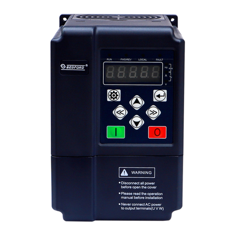
Bedford W713B Series User manual

W713B Series
Intelligent Controller
for Water Pump
User Manual
GUANGZHOU BEDFORD ELECTRIC EQUIPMENT CO.,LTD.
V1.0.0

Preface
Thanks for choosing our product W713B, we will supply you with considerate
service as well as ever.
W713B series products are not only the integrated intelligent controller designed
for water pump, but also the intelligent controller designed for the central
air-conditioning water circulation system to realize the differential constant pressure
control.
W713B intelligent controller has superior performance and rich use function,
can meet the requirement of water supply and drainage on various occasions and
improve the quality of water supply system. The product adopts the control method of
one pump and one variable frequency controller, which can effectively extend the
motor service life; the controller system supports max.6 pumps linkage work, meet
the customers’ operating requirements.
With high quality, multi-functional, low noise and strong commonality etc.
characteristics, W713B multi-function energy-saving controller is suitable to
full-automatic operation.
Suitable for various constant pressure/constant differential pressure/constant
temperature/constant differential temperature water supply applications.
After parameters were set correctly, the system can operate automatically with
constant pressure/constant differential pressure/constant temperature/constant
differential temperature according to the water consumption without manual
operation;
Alternate running automatically in the multiple pump system, prolong the
using life of pumps.
Restart automatically when power recovery
Stop running automatically when no water consumption;
Alarm automatically when faults occurred;
Suitable for various pressure signals input.

Contents
1. SAFETY PRECAUTIONS .....................................................................1
2. PRODUCT INTRODUCTION ..............................................................2
2.1 Features ......................................................................................................2
2.2 Model Specification .................................................................................. 2
2.3 Selection Guide ......................................................................................... 3
2.4 Check the Following Point ........................................................................3
2.5 External Dimension ................................................................................... 4
3. ENVIRONMENTAL REQUIREMENT .............................................. 4
4. WIRING ...................................................................................................5
4.1 Main Circuit Terminals Wiring ................................................................. 5
4.2 Control Circuits Terminals Wiring ............................................................5
4.3 Control Terminals Overall Connect .......................................................... 7
4.4 Wiring Main Circuits .................................................................................7
4.4.1 Wiring of Main Circuits ...................................................................7
4.4.2 Circuit Breaker ............................................................................... 7
4.4.3 AC Reactor (Optional) ................................................................... 8
4.4.4 Input EMC Filter (Optional) ............................................................8
4.4.5 Output EMC Filter (Optional) .........................................................8
4.4.6 Output Reactor ...............................................................................8
4.4.7 Ground Wiring ................................................................................8
5. OPERATION ...........................................................................................8
5.1 Keypad Description ...................................................................................8
5.2 Operation Procedure ..................................................................................9
5.2.1 Add Prefix Characters Display Content for Easy Understanding ..9
5.2.2 Power-on Initialization ...........................................................................9
5.2.3 Parameter Setting ..................................................................................9

6. INSTRUCTIONS OF PARAMETERS GROUP ............................... 11
7. QUICK DEBUG of PARAMETER SETTING ..................................28
8. APPLICATION GUIDANCE .............................................................. 33
8.1 Application of Constant Pressure Water Supply .....................................33
8.1.1 Single Pump Water Supply and Parameter Setting ....................33
8.1.1.1 System Wiring ...........................................................................33
8.1.1.2 System Debugging Procedure ................................................. 34
8.1.1.3 Relevant Parameter Setting ..................................................... 34
8.1.2 Multi-pump Control ...................................................................... 35
8.1.2.1 Typical System Wiring .............................................................. 35
8.1.2.2 Relevant Parameter Setting ..................................................... 36
8.2 Application of Constant Differential Pressure Water Supply ................. 39
8.2.1 Differential Pressure Control System Introduction. .....................39
8.2.2 Typical System Wiring ................................................................. 40
8.2.3 System Debugging Procedure .................................................... 41
8.2.4 Relevant Parameter Setting ........................................................ 41
8.3 Application of Constant Temperature Water Supply .............................. 44
8.3.1 Single Pump Water Supply and Parameter Setting ....................44
8.3.1.1 System Wiring ...........................................................................44
8.3.1.2 System Debugging Procedure ................................................. 44
8.3.1.3 Relevant Parameter Setting ..................................................... 45
8.3.2 Multi-pump Control ...................................................................... 45
8.3.2.1 Typical System Wiring .............................................................. 45
8.3.2.2 Relevant Parameter Setting ..................................................... 46
8.4 Application of Constant Differential Temperature Water Supply.......... 49
8.4.1 Differential Temperature Control System Introduction. ...............49
8.4.2 Typical System Wiring ................................................................. 50
8.4.3 System Debugging Procedure .................................................... 51
8.4.4 Relevant Parameter Setting ........................................................ 51

8.5 Manual/Auto Control Wiring and Setting ...............................................54
8.5.1 System Wiring ..............................................................................54
8.5.2 Operation ..................................................................................... 55
8.5.3 Relevant Parameter Setting ........................................................ 55
8.6 Electric Contact Gauge Water Supply .....................................................55
8.6.1 System Wiring ..............................................................................55
8.6.2 Relevant Parameter Setting ........................................................ 56
8.6.3 Relevant Parameter Setting ........................................................ 56
8.7 Application of One VFD Drive Two Pump .............................................56
8.7.1 Relevant Parameter Setting ........................................................ 56
8.7.2 System Debugging Procedure .................................................... 58
8.7.3 Relevant Parameter Setting ........................................................ 58
8.8 Application Summary ..............................................................................60
9. FAULT AND TROUBLE SHOOTING ...............................................60
9.1 System Running Fault and Trouble Shooting ......................................... 60
9.2 Water Supply Running Fault and Trouble Shooting ...............................61
9.3 Controller Running Fault and Trouble Shooting .................................... 62
9. COMMUNICATION PROTOCOL ....................................................63

W713B Series Intelligent Controller for Water Pump User Manual
1
1. SAFETY PRECAUTIONS
W713B is a new power electronic product, please read the operation manual
carefully before using to keep your safety and make sure proper operation.
In this manual, the safety precautions were sorted to “WARNING” and
“CAUTION”.
WARNING: Wrong using may result in death or serious personal injury.
CAUTION: Wrong using may result in the damage of controller or system.
WARNING
Please don’t dismantle, change the product, or may cause electric shock, fire hazard and
personal injury;
Please don’t open the cover during the running of controller;
Please don’t put wire, bar of metal, filaments etc. into the controller so as not to cause a
short circuit or get an electric shock;
Please don’t splash water or other liquid over the controller.
CAUTION
Please don’t make withstand voltage testing for the controller;
Never connect AC power to output UVW terminals;
If the internal components of the controller were influenced or damaged by static, please do
not to touch;
The motor, controller and power specifications should be matching, otherwise it could cause
abnormal operation even burn out the device;
If the controller appears serious vibration, noise, heat or peculiar smell in the first operation,
please cut off the power immediately and contact suppliers or service center later;
Please don’t install the controller in the environment with direct sunlight, rain, frost or snow
in case of deformation or damage.
Warm reminder:
For convenience, the controller has set default with a nonzero AI1 feedback lost
detecting value, if here hasn’t pressure signal feedback into the terminal AI1, the
controller will be starting up failure and displaying “E022”, just take follows:
◊ If the controller worked as a master, please connect a transducer to the
controller and then press the key;
◊ If it worked as an auxiliary, it should be setting as AI1 feedback lost detecting
value (b02.08) 0 and then pressing the key to reset error warning.

W713B Series Intelligent Controller for Water Pump User Manual
2
2. PRODUCT INTRODUCTION
2.1 Features
Input & Output
◆Input Voltage Range: 220V/380V±15%
◆Input Frequency Range: 47~63Hz
◆Output Voltage Range: 0~rated input voltage
◆Output Frequency Range: 0~50/60Hz
I/O Features
◆Digital Switch Input: 4 input
◆Analog Signal Input: AI1: 0~10V or 0/4~20mA input; AI2: 0~10V or 0/4~20mA input
◆Relay Output: Two pair of switch output
Function Characteristics
◆Multi-Pumps Control Function: Max.6 pump linkage water supply
◆Sleep Function: Sleep down when have no water consumption, to earn a better energy
saving
◆Freeze-Proofing Function: Suitable to low temperature area, prevent pump from
freezing
◆Anti-clogging Function: Take precaution against pipe clogging and clean the pipe dirt
◆Power On Restart: Running automatically when power on
◆Master Fault Shift Automatically: Keep on working when the master break down
◆Alternate Running: Balance every pump’s running time, prolong service life of the
whole unit machine
◆Control Mode: Constant pressure, constant differential pressure, constant temperature,
constant differential temperature, manual
◆Linkage Mode: Synchronize, master-slave, big-small pump combination, one duty one
standby, one VFD drives two pump (in conjunction with control electric cabinet).
◆Terminal Control Mode: Electronic contact gauge control, manual/auto control,
terminal run/stop, automatic water level control, one VFD drives two pump fault input.
◆Various of Water Supply Fault Alarm Function: High-pressure, low-pressure, low-level,
transducer error etc.
◆Many Fault Protection Function: Over-current, over-voltage, low-voltage, phase-failure,
over-Load etc.
◆Scalability: Can be connected to our company touch screen(HMI)
2.2 Model Specification
W713B-4 010
Power Symbol 010: 10HP/7.5kW
Voltage Class 2: 220VAC 4: 380VAC
Series Number of Intelligent Controller for Water Pump

W713B Series Intelligent Controller for Water Pump User Manual
3
2.3 Selection Guide
Table2.3.1 W713B list
Model No.
Rated Input
Voltage (V)
Rated Input
Current (A)
Rated Output
Current (A)
Motor Power
(kW)
W713B-2001
1AC: 220V
-15%~+15%
7.1
4.5
0.75
W713B-2002
11.1
7.0
1.5
W713B-2003
15.8
10.0
2.2
W713B-2001
3AC: 220V
-15%~+15%
7.1
4.5
0.75
W713B-2002
11.1
7.0
1.5
W713B-2003
15.8
10.0
2.2
W713B-2004
17.6
13.0
3.0
W713B-2005
23.0
17.0
3.7
W713B-2007
32.0
25.0
5.5
W713B-2010
40.0
32.0
7.5
W713B-4001
3AC: 380V
-15%~+15%
3.4
2.1
0.75
W713B-4002
5.0
3.8
1.5
W713B-4003
5.8
5.1
2.2
W713B-4004
13.5
9.5
4.0
W713B-4005
19.5
14.0
5.5
W713B-4007
25.0
18.5
7.5
W713B-4010
32.0
25.0
11.0
W713B-4015
40.0
32.0
15.0
W713B-4020
47.0
38.0
18.5
2.4 Check the Following Point
Inspect the nameplate and ensure it meets the order type and specification;
Inspect the entire exterior of the controller to ensure there are no scratches or
other damage caused by the transportation;
Ensure the guarantee odd number matches the controller;
If you have found any problem mentioned above, please contact the supplier.

W713B Series Intelligent Controller for Water Pump User Manual
4
2.5 External Dimension
Figure2.5.1 Dimension
Model
(kW)
External Dimension
H (mm)
W (mm)
D (mm)
220V: 0.75~2.2 (380V: 0.75~3.0)
170
190
110
220V: 3.0~3.7 (380V: 4.0~7.5)
205
235
120
220V: 5.5~7.5 (380V: 11.0~18.5)
220
290
150
3. ENVIRONMENTAL REQUIREMENT
1. Environment temperature range: -10℃~40℃, controller will be derated at 4% on
every 1℃if ambient temperature exceeds 40℃, the maximum temperature is less
than 50℃.
2. Prevent rain drops, moist environment, oil fog, salt erosion, corrosive gas, etc..
3. Prevent direct sunlight, keep away from radiation source.
4. Prevent violent vibration or sudden impact.
5. Lower than 1000m installation altitude, if exceeds 1000m, inverter will be derated
at 1% on every 100m.
CAUTION
When moving the controller please lift by its base and don’t lift by the panel. Otherwise may
cause the main unit fall off which may result in personal injury.
Install the controller on the fireproofing material (such as metal) to prevent fire.
When power off, should not install the controller until the power indicator light was
extinguished, which can ensure the device has been discharged completely.
Disconnect all power line before opening front cover of unit. Wait at least 5 minute until DC
Bus capacitors discharge.

W713B Series Intelligent Controller for Water Pump User Manual
5
4. WIRING
4.1 Main Circuit Terminals Wiring
PE
R/L
S/N
T
U
V
W
PE
Figure 4.1.1 The main circuit terminals
2. Main circuit terminal’s function as following:
Terminal Symbol
Function Description
L, N
Terminals of single phase AC input
R, S, T
Terminals of 3 phase AC input
U, V, W
Motor wiring terminal
PE
Terminals of ground
In order to keep safety and prevent electric shock and fire, “PE” must be
grounded with ground resistance. Furthermore, reliable grounding is the simplest,
most effective and minimum cost solution for EMC problems, so it enjoys priority in
all EMC methods.
4.2 Control Circuits Terminals Wiring
Figure 4.2.1 Control circuits terminals wiring
Manual/Auto Switchover Function (Constant Speed/Constant Pressure
(Constant Differential Pressure/Constant Temperature/Constant Differential
Temperature) Switchover Function):
(1) Terminal (Terminal in priority, panel keypad control manual/auto switchover
invalid)
When b05.02 = 2, S2 disconnected with COM, and constant pressure/constant
differential pressure/constant temperature/constant differential temperature water

W713B Series Intelligent Controller for Water Pump User Manual
6
supply is provided. The set pressure/differential pressure/temperature/differential
temperature under the primary interface can be adjusted by pressing or
key. S2 connected with COM, operate and supply water at constant speed, and the
constant speed operation frequency under the primary interface can be adjusted by
pressing or key.
(2) Panel Keypad (Manual/Auto Switchover can be realized by pressing the panel
button when the inverter is stopped)
In the stop state, press the and key at the same time in the primary
display interface to realize the manual/automatic switchover.
The functions of the control terminal are described below:
Type
Terminal
symbol
Terminal Name
Function Description
Power
Source
P5V-VCM
10mA output terminal
(Load is less than 1kΩ)
Providing 10mA current (Load is less than 1kΩ),
used for external resistance type remote pressure
gauge
+24V-GND
24V power source
Providing 24V power source, used for pressure
transmitter, the max.output current
Analog
Input
+24V-AI1
Analog input terminal 1
Reception of 0/4mA~20mA pressure transmitter,
Plug in jumper cap on control panel P1.
+24V-AI2
Analog input terminal 2
Digital
Input
S1-COM
Digital Input 1
ON-OFF signal input, optical coupling with +24V
and COM
Input voltage range: 9V~30V
Input impedance: 2.4kΩ
S2-COM
Digital Input 2
S3-COM
Digital Input 3
S4-COM
Digital Input 4
Relay
Output
T/A-T/B
NC terminal
The relay switch contact signal, which can be
either alarm or valve switch signals.Max.capacity
of contact: AC 250V- 3A or DC 30V-1A.
T/A-T/C
NO terminal
P/A-P/C
NO terminal
Commu-
nication
485A+
First pair RS485
communication
terminal
485 communication interface and internal
communication interface, please use twisted pair
or shield wire
485A-
485B+
Second pair RS485
communication
terminal
485 communication interface and external
communication interface, please use twisted pair
or shield wire
485B-
Remarks
P1
The AI1 and AI2 input
type selector switch
Plug in the short circuit cap as current signal,
otherwise voltage signal
P2
485B communication
terminal resistance
selection
Plug the short circuit cap to connect the
terminal resistance and otherwise.
Note that plug the short- circuit caps on
the first and tail two when multiple
pumps are online. that for multi-pump, only
open toggle switch of the first pump and last
pump.
P3
485A communication
terminal resistance
selection

W713B Series Intelligent Controller for Water Pump User Manual
7
4.3 Control Terminals Overall Connect
Figure 4.3.1 Wiring diagram
4.4 Wiring Main Circuits
4.4.1 Wiring of Main Circuits
Figure4.4.1 High-performance main circuit wiring
4.4.2 Circuit Breaker
It is necessary to connect a suitable circuit breaker between 3 phase AC power
supply and W713B series intelligent constant water supply controller. The capacity of
breaker is 1.5~2 times to the rated current of controller.

W713B Series Intelligent Controller for Water Pump User Manual
8
4.4.3 AC Reactor (Optional)
In order to prevent the rectifier damage resulted from the large current, AC
reactor should be installed at the input side. It can also prevent rectifier from sudden
variation of power voltage or harmonic generated by phase-control load.
4.4.4 Input EMC Filter (Optional)
EMC filter can minimize the interference of the surrounding device which may
be disturbed by the cables when the controller is working.
4.4.5 Output EMC Filter (Optional)
EMC filter should be installed to minimize the leak current caused by the cable
and minimize the radio noise caused by the cables between the controller and motor.
4.4.6 Output Reactor
When the distance between the W713B controller and motor is more than 50m,
the controller may be tripped by over-current protection frequently because of the
large leak current resulted from the parasitic capacitance with ground. So as to avoid
the damage of motor insulation, the output reactor should be installed.
4.4.7 Ground Wiring
In order to keep safety and prevent electric shock and fire, “PE” must be
grounded with ground resistance. Furthermore, reliable grounding is the simplest,
most effective and minimum cost solution for EMC problems, so it enjoys priority in
all EMC methods.
5. OPERATION
5.1 Keypad Description
Figure5.1.1 Keypad schematic diagram

W713B Series Intelligent Controller for Water Pump User Manual
9
5.2 Operation Procedure
5.2.1 Add Prefix Characters Display Content for Easy Understanding
H: Operating Frequency
P: The Actual Pressure of Pump Outlet
/The Actual Differential Pressure (Outlet Pressure -Inlet Pressure)
/The Actual Temperature of Pump Outlet
/The Actual Differential Temperature (Outlet Temperature - Inlet Temperature)
L: The Setting Pressure of Pump Outlet
/The Setting Differential Pressure (Outlet Pressure -Inlet Pressure)
T: The Setting Temperature of Pump Outlet
/The Setting Differential Temperature (Outlet Temperature -Inlet Temperature)
A: Output current
d: DC Bus Voltage
: The Setting Pressure of Pump Outlet and Actual Pressure of
Pump Outlet
/The Setting Differential Pressure and Actual Differential Pressure
/The Setting Temperature of Pump Outlet and Actual Temperature Pressure of
Pump Outlet
/The Setting Differential Temperature and Actual Differential Temperature
: The Output Current and The Actual Pressure of Pump Outlet
/The Output Current and Actual Differential Pressure
/The Output Current and Actual Temperature of Pump Outlet
/The Output Current and Actual Differential Temperature
5.2.2 Power-on Initialization
Firstly the system initializes during the controller power-on, and LED displays
“713b”. After the initialization is completed, the controller is on stand-by status.
5.2.3 Parameter Setting
Three levels of menu are: 1. Function code group (first-level); 2. Function code
(second-level); 3. Function code setting value (third-level)
▲At the primary interface, press will switch over display running/stop
status monitoring parameters;

W713B Series Intelligent Controller for Water Pump User Manual
10
▲At the primary interface, press will enter the first-level menu then press
will return to the primary interface;
▲At the first-level menu, press will enter the second-level menu. In
second-level menu can also press and return to first-level menu or
enter third-level menu;
▲At third-level menu, press or can return to the second-level menu,
difference is: pressing will save the parameters into the controller and
return to the second-level menu with shifting to the next function code
automatically; while pressing will directly return to the second-level
menu without saving the parameters, and keep staying at the current function
code.
Example 1: Change factory pressure setting 3.0 bar to 2.5 bar
Method 1: Enter parameter setting
Operation flow chart:
Figure 5.2.1 Operation flow chart

W713B Series Intelligent Controller for Water Pump User Manual
11
Method 2: Direct setting at the primary interface
Press or at primary interface, the system will switch-over to display
setting pressure, press or again, the setting pressure increase/decrease,
mean while the system trace the setting pressure.
6. INSTRUCTIONS OF PARAMETERS GROUP
“○”:stands for the inverter is in stop or running status,the parameter can be
changed;
“◎”:stands for the inverter is in running status,the parameter can not be
changed;
“●”:Stand for the parameter can not be changed.
Function
Code
Name
Setting
Range
Factory
Setting
Description
R/W
Address
br-00 Group Application Function
b00.00
Function
Debugging
Password
0~65535
65535
Decide by b06.09, default is 65535
—
—
b00.01
Pressure Setting
b01.01
~b01.00-1.0
3.0bar
Set Pressure/Set Differential Pressure/Set
Temperature/Set Differential Temperature
According to mode (b01.18) selection and
automatically adjust factory setting according
to the responding mode.
○
0xB001
Differential
pressure setting
0.0
~b01.00-1.0
0.5bar
Temperature
Setting
-15.0
~b01.20-10
30.0℃
Differential
Temperature
5.0℃
b00.02
Setting
Motor Rotating
Direction
0~1
0
0: Forward;
1: Reverse
◎
0xB002
b00.03
Freeze-proofing
0~1
0
Used in cold areas. 0: Invalid; 1: Valid
◎
0xB003
b00.04
Anti-clogging
0~1
0
It is only suitable for single pump system
to remove water pump rust blockage and
pipeline blockage. 0: Invalid; 1: Valid
◎
0xB004
b00.05
Anti-clogging
Rotating Cycle
1.0~300.0
20.0s
Set the forward/reverse rotating direction
cycle and corresponding output frequency
(should not be higher than the rated
frequency of the pump) of anti-clogging.
○
0xB005
b00.06
Anti-clogging
Output
Frequency
0.00~b05.05
15.00Hz
○
0xB006
b00.07
Shortcut Key
Setting
0x100
~0x651
0x100
◎
0xB007

W713B Series Intelligent Controller for Water Pump User Manual
12
Function
Code
Name
Setting
Range
Factory
Setting
Description
R/W
Address
b00.08
Constant Speed
Operating
Frequency
Setting Value
b05.07
~b05.06
50.00Hz
When the constant speed operating frequency
needs to be set to a greater value, the upper
operating limit b05.06 shall be modified first,
and then the value shall be modified
○
0xB008
b00.09
Manual
Frequency
Source
Selection
0~3
0
0: Keyboard (b00.08); 1: AI1;
2: AI2; 3: Communications control
◎
0xB009
br-01 Group Application Function
b01.00
High Water
Pressure Alarm
Value
b01.01+1.0
~b01.05
8.0bar
When actual pressure on the outlet side is
higher than this preset value, the inverter
halts, alarms and displays “HP”.
Constant Pressure Mode: When actual
pressure on the outlet side is lower than this
preset value, “HP” would be automatically
cleared,When actual pressure on the outlet
side is lower than the difference value
between this preset value and bias value
(b04.03), pump would restart automatically.
Constant Differential Pressure Mode:
When actual pressure on the outlet side is
lower than the difference value between this
preset value and 1.5 Bar, “HP” would be
automatically cleared and pump would restart
automatically.
○
0xB100
b01.01
Low Water
Pressure Alarm
Value
0.0~b01.00
0.5bar
Outlet side Low Water Pressure Alarm Preset
Value
○
0xB101
b01.02
Low Pressure
Running Time
0.0~3600.0
20.0s
When the “Constant Pressure” or
“Constant Differential Pressure” Control
Modes are in operation, the actual pressure
on the outlet side is lower than the low water
pressure alarm value (b01.01) for a low
pressure running time (b01.02), the inverter
halts, alarms and displays “LP”;
When the “Constant Temperature” or
“Constant Differential Temperature”
Control Modes are in operation, the actual
temperature on the outlet side is lower than
the low temperature alarm value (b01.29) for
a low temperature running time (b01.02), the
inverter halts, alarms and displays “LT”.
○
0xB102
Low
Temperature
Running Time

W713B Series Intelligent Controller for Water Pump User Manual
13
Function
Code
Name
Setting
Range
Factory
Setting
Description
R/W
Address
b01.03
Minimum
Freeze-proofing
Frequency
1.00~b05.07
5.00Hz
Be valid when b00.03 was set to 1, when
sleep, running with the setting frequency in
case of freezing. This value should be lower
than the lower limited frequency (b05.07).
○
0xB103
b01.04
Anti-clogging
FWD./REV.
Dead Time
0.0~3600.0
1.0s
When anti-clogging is valid, b01.04 set the
FWD./REV. transition time
○
0xB104
b01.05
Maximum
Transducer
Setting Range
0.0~100.0
10.0bar
For “Constant Pressure” or “Constant
Differential Pressure” Control Mode. If the
rated max. range of transducer is 16.0bar,
b01.05 should be set to 16.0;
Set the control range of “Constant
Temperature” or “Constant Differential
Temperature” in parameters b01.07 and
b01.09 (water outlet), b01.12 and b01.14
(water inlet).
○
0xB105
b01.06
AI1 Lower
Limit
0.00~b01.08
1.00V
Lower limit (b01.06, b01.11) use to
transducer zero setting
Corresponding Setting of Lower Limit
(b01.07, b01.12) use to transducer
minimum setting
Higher limit (b01.08, b01.13) use to
accordant display and transducer: when
display smaller than the actual, decrease
higher limit; when display greater than the
actual, increase higher limit
Corresponding Setting of Higher Limit
(b01.09, b01.14) use to transducer
maximum setting
When analog input is interfered, prolong
filtering time so as to increase the ability of
anti-interference, but decrease the
sensitivity.
Corresponding relationship of transducer
parameter setting of “Constant Pressure”
and “Constant Differential Pressure”
control mode:
○
0xB106
b01.07
Corresponding
Setting of AI1
Lower Limit
-100.0~200.0
0.0%
○
0xB107
AI1
Temperature
Lower Limit
0.0℃
b01.08
AI1 Higher
Limit
b01.06
~10.00
5.00V
○
0xB108
b01.09
Corresponding
Setting of AI1
Higher Limit
-100.0~200.0
100.0%
○
0xB109
AI1
Temperature
Higher Limit
100.0℃
b01.10
AI1 Filtering
Time
0.00~10.00
0.10s
○
0xB10A
b01.11
AI2 Lower
Limit
0.00~b01.13
1.00V
○
0xB10B
b01.12
Corresponding
Setting of AI2
Lower Limit
-100.0~200.0
0.0%
○
0xB10C
AI2
Temperature
Lower Limit
0.0℃
b01.13
AI2
Hi
gh
er
b01.11
5.00V
○
0xB10D

W713B Series Intelligent Controller for Water Pump User Manual
14
Function
Code
Name
Setting
Range
Factory
Setting
Description
R/W
Address
Corresponding relationship of transducer
parameter setting of “Constant
Temperature” and “Constant differential
Temperature” control mode:
Li
m
i
t
~10.00
b01.14
Co
rre
spond
i
ng
S
e
tt
i
ng of AI2
Hi
gh
er Li
m
i
t
-100.0~200.0
100.0%
○
0xB10E
AI2
Te
mp
er
atu
re
Hi
gh
er Li
m
i
t
100.0℃
b01.15
AI2
Fil
t
eri
ng
Ti
m
e
0.00~10.00
0.10s
○
0xB10F
b01.16
Restart After
Power-on
0~1
1
0: Invalid;
1: Valid
◎
0xB110
0
1
0
b01.17
Linkage Mode
0~4
1
0: Synchronous; 1: Master-slave;
2: Big-small pump combination;
3: One duty one standby;
4: One VFD drive two pumps (It needs to be
used with One VFD drive two pumps boxes)
Note: when b01.17 was set to 4, the
following parameters will be set
automatically. b01.09 is 0 (Independent Start
and Stop Forbidden), b05.02 is 5 (One VFD
drives two pump fault input), b05.12 is 1 (S4
terminal control), b06.03 is 10 (Relay 1 used
for variable frequency pump control), b06.10
is 11 (Relay 2 used for power frequency
pump control).
◎
0xB111
b01.18
Control Mode
0~3
0
0: Constant Pressure;
1: Constant Differential Pressure;
2: Constant Temperature;
4: Constant Differential Temperature
◎
0xB112
b01.19
Independent
Start and Stop
Control
0~1
0
Only be enabled when b05.02 =2 and
b01.17≠4
0: Invalid (Start and stop is controlled by the
system after being put into the system)
1: Valid (Start and stop is controlled by the
inverter, which can be started and stopped by
the panel or S4 terminal)
◎
0xB113
b01.20
One VFD drive
two pumps mode
0~1
1
0: Fixed variable frequency pump
1: Rotate variable frequency pump
When enabled, the alternate mode is
◎
0xB114

W713B Series Intelligent Controller for Water Pump User Manual
15
Function
Code
Name
Setting
Range
Factory
Setting
Description
R/W
Address
determined by b05.11, and the alternate time
is set by b05.10.
Note: After the alternate time reaches, when
the sleep function is enabled, the system will
automatically complete the alternate while
sleeping. When the sleep function is not
enabled, the system will complete the
alternating at the lower limit of output
frequency.
b01.21
Add Power
Frequency Pump
Pressure Bias
0.0~b00.01
0.5bar
Bias Value of Setting Pressure /Setting
Differential Pressure /Setting Temperature
/Setting Differential Temperature subtract
Feedback Pressure /Feedback Differential
Pressure /Feedback Temperature /Feedback
Differential Temperature
○
0xB115
Add Power
Frequency Pump
Differential
Pressure Bias
0.5bar
Add Power
Frequency Pump
Temperature
Bias
5℃
Add Power
Frequency Pump
Differential
Temperature
Bias
5℃
b01.22
Add Power
Frequency Pump
Delay Time
0.0~3600.0
10.0s
When Variable Frequency Pump reach Upper
Limit Frequency, if the difference value of
Setting Pressure /Setting Differential Pressure
/Setting Temperature /Setting Differential
Temperature subtract Feedback Pressure
/Feedback Differential
Pressure /Feedback Temperature /Feedback
Differential Temperature is higher than or
equals to b01.21, after b01.22 delay time,
Power Frequency Pump would be in
operation.
○
0xB116
b01.23
Subtract Power
Frequency Pump
Pressure Bias
0.0~b00.01
0.5bar
Bias Value of Feedback Pressure /Feedback
Differential Pressure/Feedback Temperature
/Feedback Differential Temperature subtract
Setting Pressure /Setting Differential Pressure
/Setting Temperature /Setting Differential
○
0xB117
Subtract Power
Frequency Pump
Differential
Pressure Bias
0.5bar
This manual suits for next models
16
Table of contents
Other Bedford Controllers manuals
