9
UG-681
WirelessAIR
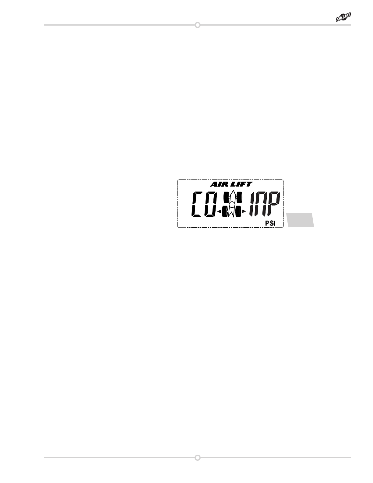
g. 12
Replacement Information
If you need replacement parts, contact the local dealer or call Air Lift customer service at
(800) 248-0892. Most parts are immediately available and can be shipped the same day.
Contact Air Lift Company customer service at (800) 248-0892 rst if:
• Parts are missing from the kit.
• Need technical assistance on installation or operation.
• Broken or defective parts in the kit.
• Wrong parts in the kit.
• Have a warranty claim or question.
Contact the retailer where the kit was purchased:
• If it is necessary to return or exchange the kit for any reason.
• If there is a problem with shipping if shipped from the retailer.
• If there is a problem with the price.
Contact Information
If you have any questions, comments or need technical assistance, contact our customer
service department by calling (800) 248-0892, Monday through Friday, 8 a.m. to 5 p.m. Eastern
Time. For calls from outside the USA or Canada, our local number is (517) 322-2144.
For inquiries by mail, our address is PO Box 80167, Lansing, MI 48908-0167. Our shipping
address for returns is 2727 Snow Road, Lansing, MI 48917.
www.airliftcompany.com.
2. The WDC is unable to get any status information from the manifold for 10 seconds, in
which case the WDC will return to Sleep Mode.
3. Three minutes have passed since the settings were sent, in which case the WDC will
return to Sleep Mode.
MANIFOLD OPERATION:
The current air bag pressure settings will be automatically maintained by the system subject
to the following constraints:
1. The maximum pressure is 100 PSI (see your air bag’s installation manual for individual
maximum ination pressure).
2. The minimum pressure is 5 PSI.
3. In general, the system will not dump air from an air bag circuit unless commanded by the
user. The only exception is if the average air bag pressure exceeds 110 PSI, in which
case it will be bled down to below 110 PSI.
4. The system will limit continuous compressor operation to 3 minutes. After 3 minutes,
the system will lock out all compressor operations until power is cycled, or a 7 minute
cooling period takes place (g. 12).