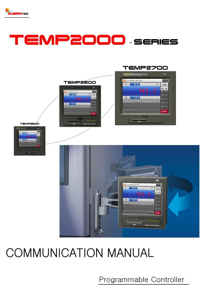
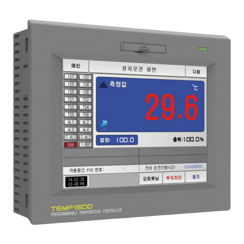
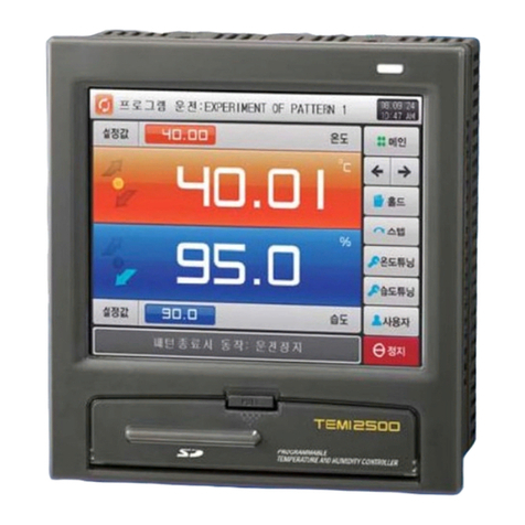
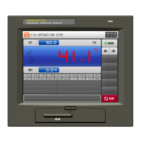
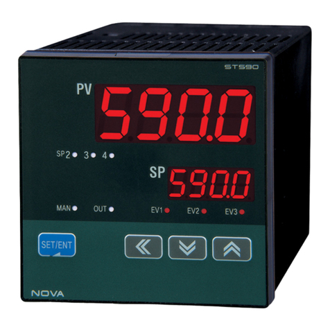
Samwontech NOVA541 User manual

N
NO
OV
VA
A5
54
41
1
Digital Controller ST541
User’s Manual
SAMWONTECH CO., Ltd.

NOVA541
- 1 -
Limitations in use
Thank you very much for the purchase of SP541 PROGRAM CONTROLLER.
This User’s Manual explains the Installation and Operation Procedures.
The safety considerations and the right way of use are also included in it. A
designer of the control panel, an Engineer of maintenance and users should
read it and understand the necessary items before use.
This manual is also necessary for repairing, trouble shooting as well as an
installation.
Keep it near at hand and use it as a reference.
This product was designed and manufactured for general industrial equipments.
Special cares on safety is required in the case of using in following equipments.
Users should take precautionary measures on Fail Safe design, periodical checkup,
safety of the whole system.
▪Safety Devices for protecting human body.
▪Direct control of vehicles (navigation, run and stop)
▪Airplanes
▪Self-control Equipments
▪Nuclear Power Equipments
Do not use for any purpose which affects the human body.

NOVA541
- 2 -
Important Safety Guide
To prevent an accident of injury, All the Installers and users should keep the safety
rules in this manual.
SAFETY SYMBOL MARKS
(A) “Handle with Care” , “Precaution”: The operator must read and keep in mind the explanation
because it is critical to protect a person or an instrument.
(1) On Product : The essential items the operator should know to prevent accidental injury
or damage of the instrument.
(2) In User’s Manual : For the precautions necessary to prevent an accidental electric
shock.
(B) “Protective Ground Terminal”.
Prior to operating, the terminal must be connected to the Ground.
(C) “Supplementary Explanations”.
Additional information on the operation and features of the product
(D) “Reference Information”
Further information on the current topic and pages to refer
Precautionary Remarks on this User’s Manual
(1) This manual should be passed on the end user and kept at a suitable place for easy
review.
(2) Before using the product, the operator should read this book carefully and understand
the operation procedure.
(3) This manual describes the functions of the product in detail. Samwontech does not
☞☞

NOVA541
- 3 -
warrant that the functions will suit a particular purpose which is not described in this
manual.
(4) Without permission, the contents of this manual cannot be transcribed or copied in
part or wholly.
(5) The contents of this manual may be modified without previous notice.
(6) If any errors or omissions in this manual should come to the attention of the user,
feel free to contact our sales representatives or our sales office.
Regarding Safety and Unauthorized Modification
(1) For the protection and safe use of the product and relevant system, all of the safety
instructions and precautions are well recognized and strictly observed by all users.
(2) Samwontech does not guarantee safety if the product is not handled according to
this manual.
(3) If additional safety circuits for protection of system is required, Install them at outside
of this product not at inside.
(4) Don’t try to disassemble, repair, or modify the product. It may become the cause of
a trouble such as malfunction, electric shock, fire.
(5) When part replacement or consumables are needed, call to our sales office.
(6) Keep this product from moisture. It may become a cause of trouble.
(7) Be careful not to apply any shock or vibration to the product. It may cause damage
or malfunction.
Regarding an exemption from responsibility
(1) Samwontech co., Ltd does not make any warranties regarding the product except
Warranty conditions which mentioned in this manual.
(2) Samwontech assumes no liability to any party for any loss or damage, direct or
indirect, caused by the use or any unpredictable defect of the product.

NOVA541
- 4 -
Regarding the Production Quality Assurance
(1) The guaranteed period of the production quality assurance is one year after end use
by it and it will be free of charge to fix defective product under regular usage
described in this manual.
(2) The fixing cost will be charged for defective product after warranty period. This
charge will be the actual cost of the fixing estimated by Samwontech.
(3) It will be charged even if within warranty period for following cases.
(a) Defect by an operator or the user’s default. (Initialize the product, forget password)
(b) Natural disaster (fire, flood)
(c) Additional shift after the first installation
(d) Improperly repaired, altered, or modified by the user.
(e) Power failure by unstable power supply
(4) If any A/S is required, feel free to contact our sales office or a representative.

NOVA541
- 5 -
Precautions on Environment and Installations
Environmental Precautions
(1) Be sure to power on and operate the controller after installation on a panel to prevent
electric shock.
(2) Do not install the controller at following places or environment
■ Anybody may touch the terminal inadvertently
■Mechanical vibration or shock
■ Corrosive gas or combustible gas
■ Temperature fluctuation
■ Too hot (> 50℃) or Cold (< 10℃)
■ Direct rays of light or heat radiation
■ Magnetic or electromagnetic noise
■ High humidity ( > 85%)
■ Flammable materials
■ Wind blow, Dust with salt
■ Ultra violet rays
Precautions on Controller Mounting
(1) Keep the controller away from possible noise sources.
(2) Keep the controller in 10∼50℃, 20∼90%RH (non condensing) and be careful not to
expose heat generating sources.
(3) Do not mount with a position that the front panel facing downward
(4) Storage should be within -25∼70℃, 5∼95%RH (non condensing). At a cold
condition below 10℃, sufficient warming-up should be preceded by the control
operation.

NOVA541
- 6 -
(5) Turn off the main power of the control unit before wiring to prevent electric shock.
(6) The power rating of the controller is 10 VA max. at 100∼240VAC, 50/60Hz. Be sure
to use suitable power source to prevent overheating or electric shock.
(7) Do not work with wet hands to prevent electric shock.
(8) The precautions and procedures in the manual should be kept to avoid a hazard
such as fire, injury, and electric shock.
(9) Installation and Operation procedures should be done just as in this manual.
(10) Make the grounding connection according to the way in manual. Do not use a tap
water piping, a gas pipe, a telephone line, a lightning rod to avoid possible accidents
such as explosion or inflammation.
(11) Do not power on the controller before the wiring procedure is not completed.
(12) Do not block or wrap the heat vent holes in the case of the controller. That may
cause a failure. Air gaps greater than 50 mm is necessary on the upper and bottom
sides of the controller.
(13) Over-voltage protection category II and Pollution Degree II are rated for the
controller.

NOVA541
- 7 -
Engineering Units –EU, EUS
▶EU and EUS are used for the scaling of the parameters of the controller.
☞EU( ) : The Range of the Instrument, Engineering Unit
☞EUS( ) : The Range of the span of the Instrument, Engineering Unit
▶The Range of EU( ), EUS( )
RANGE
CENTER POINT
EUS-100 ~ 100%
RL ~ RH
| RH –RL | / 2 + RL
EUS -100 ~ 100%
- ( | RH –RL | + | RL | ) ~ RH
RL
EUS -100 ~ 100%
0 ~ | RH –RL |
| RH –RL | / 2
EUS -100 ~ 100%
- | RH –RL | ~ | RH –RL |
0
▶INPUT = TC.K2
▶RANGE = -200.0℃(RL) ~ 1370.0℃(RH)
RANGE
CENTER POINT
EUS-100 ~ 100%
- 200.0 ~ 1370.0℃
585.0℃
EUS -100 ~ 100%
- 1770.0 ~ 1370.0℃
- 200.0℃
EUS -100 ~ 100%
0 ~ 1570.0℃
785.0℃
EUS -100 ~ 100%
- 1570.0 ~ 1570.0℃
0.0℃
☞ABS denotes absolute value and does not change with input.
|RH|
|RL|
EU 0~100%
EU -100~100%
|RH - RL|
EUS -100~100%
|RH| - |RL|
EUS 0~100%
RL
RH
0

NOVA541
- 8 -
Alpha-numeric Displays of the product
Numbers in 7-Segment LED Display
0
1
2
3
4
5
6
7
8
9
.
-
/
Half -
Half 1
Half -1
Alphabets in 7-Segment LED Display
A, a
B, b
C, c
D, d
E, e
F, f
G, g
H, h
I, i
J, j
K, k
L, l
M, m
N, n
O, o
P, p
Q, q
R, r
S, s
T, t
U, u
V, v
W, w
X, x
Y, y
Z, z
Note : Numeric 5 and alphabet S appear the same way

NOVA541
- 9 -
CONTENTS
Important Safety Guide
Precautions on Environment and Installations
Engineering Units –EU, EUS
Alpha-numeric Displays of the product
PAGE
1. Introduction 14
1-1 Product outline 14
1-2 KEY Operaion 17
1-2-1 Part names and functions 17
1-2-2 KEY Operation 18
1-2-3 Front panel and LEDs 20
1-3 Terminal layout and connection diagram 21
1-3-1 Terminal layout 21
1-3-2 Connection diagram 21
1-4 Parameter Map (deployment diagram) 22
1-4-1 Parameter Flow 22
1-5 Initial parameter setting sequence 24
2. Electrical wiring 25
2-1 Power cable specification 25
2-2 Terminal connector specification 25
2-3 Countermeasures against noise 25
2-4 Wiring 26
2-4-1 Ground and power source 26
2-4-2 Sensor input 26
2-4-3 Control out 27
2-4-4 Digital output and input 28
2-4- Auxiliary Relay 29
2-4-6 CT sensor for detecting Heater Break 30
2-4-7 Front communication port 30
3. Mounting of the product 31
3-1 Dimensions 31
3-2 Panel cut-out size 31
3-2-1 Close-packed mounting 31
3-2-2 General mounting 31

NOVA541
- 10 -
3-3 Mounting procedure 32
3-4 Disassembly of TERMINAL CASE ASSY and wiring 33
4. Functions 34
4-1 Sensor input (G.IN) 34
4-1-1 Input Type 35
4-1-2 Temperature unit 35
4-1-3 Input range 35
4-1-4 Decimal point 35
4-1-5 PV display range 36
4-1-6 Input filter 36
4-1-7 Display filter 37
4-1-8 Burn-out detection 37
4-1-9 Reference Junction Compensation 37
4-1-10 Entire-range correction 38
4-1-11 Piecewise correction 38
4-1-12 PV Limiter 39
4-2 Control output (G.OUT) 41
4-2-1 Output Kinds 41
4-2-2 Output control direction 42
4-2-3 Output period (Cycle Time) 42
4-2-4 Output limit 43
4-2-5 Output change rate 43
4-2-6 Hysteresis 43
4-2-7 ON/OFF mode 44
4-2-8 Output in an emergency 44
4-2-9 OUT LED display 46
4-3 Control Functions (G.CTL) 47
4-3-1 Reservation RUN 47
4-3-2 RUN time setting 47
4-3-3 Auto/Manual Selection 47
4-3-4 User Screen 47
4-3-5 User defined key 48
4-3-6 Key Lock 48
4-3-7 External Contact Input (DI) 48
4-3-8 Output Status display 48
4-3-9 PV Display High, Low Limit 49

NOVA541
- 11 -
4-3-10 PASSWORD 49
4-3-11 ON/OFF Mode 49
4-3-12 Initialization of the controller 49
4-4 Communication (G.COM) 50
4-4-1 Protocol selection 50
4-4-2 Baud rate 50
4-4-3 Parity 50
4-4-4 Stop Bit 50
4-4-5 Data Length 50
4-4-6 Communication Address 51
4-4-7 Response Time 51
4-4-8 Remote Bias at Synchronized RUN 51
4-5 Auto Tuning (G.AT) 52
4-5-1 Auto tuning 53
4-5-2 GAIN setting 53
4-6 Alarm (G.ALM) 55
4-6-1 Alarm Types 58
4-6-2 Alarm points 58
4-6-3 High/Low Deviation Alarm 58
4-6-4 Dead Band 59
4-6-5 Delay Time 59
4-6-6 SK.DV Setting 59
4-7 SP Group (G.SP) 61
4-7-1 RUN/STOP selection 61
4-7-2 SP Kind 61
4-7-3 SP Setting 61
4-7-4 High / Low Limit 61
4-7-5 Time unit 61
4-7-6 Slope of ramping up/down 62
4-8 PID Group (G.PID) 63
4-8-1 ARW (Anti Reset Wind-up) 64
4-8-2 Control Mode 64
4-8-3 Fuzzy Function 65
4-8-4 PID Number 65
4-8-5 Proportional band 65
4-8-6 Integration time 66

NOVA541
- 12 -
4-8-7 Derivation time 66
4-8-8 Manual set value of Integration time 66
4-8-9 Proportional band (cooling control) 66
4-8-10 Integration time (cooling control) 66
4-8-11 Derivation time (cooling control) 66
4-8-12 DEAD BAND 66
4-8-13 PID Zone setting 67
4-8-14 PID DEAD BAND 67
4-8-15 Deviation value used in deviation PID 67
4-9 Inner Signal Group (G.IS) 69
4-9-1 Type to be referenced (.IST) 69
4-9-2 Out or In band (.ISB) 69
4-9-3 High/Low limits of band (.ISH, .ISL) 69
4-9-4 Delay Time (.ISD) 69
4-10 Retransmission Group (G.RET) 72
4-10-1 Type of retransmission (RET) 72
4-10-2 High and low limits (RETH, RETL) 73
4-11 Heater Break Alarm 74
4-11-1 Heater Current Display 74
4-11-2 Heater Current Alarm Point 74
4-11-3 Dead band 74
* Error Display and correction 76
5. Communication (G.COM) 77
5-1 Outline 77
5-2 Wiring of communication 77
5-3 Communication parameters 78
5-4 Standard protocol 79
5-4-1 Communication Command 79
5-4-2 General Command 80
5-4-2-1 Read Command 80
5-4-2-2 Write Command 82
5-4-2-3 Monitoring Command 83
5-4-3 Information Command 85
5-4-4 Error Code 86
5-5 MODBUS protocol 87
5-5-1 Communication Function Code 87

NOVA541
- 13 -
5-5-1-1 Function code-03 87
5-5-1-2 Function code-06 88
5-5-1-3 Function code-08 89
5-5-1-4 Function code-16 90
5-5-2 Error Code 91
5-6 SYNC Communication 92
5-6-1 SYNC-Master 92
5-6-2 SYNC-Slave 92
5-7 D-Register Map 93
5-7-1 Process 93
5-7-2 Function 94
5-7-3 Set Point 94
5-7-4 Signal 95
5-7-5 Alarm 95
5-7-6 PID 96
5-7-7 IN/OUT 97
* D-Register 0000∼0499 99
* D-Register 0500∼0999 101
* D-Register 1000∼1399 103
* BIT-MAP Information 105

NOVA541
- 14 -
1. INTRODUCTION
1-1. Product Outline
ST541 is a digital controller with advanced design and functions. Short body (78 mm) is convenient
to install at a small space. More informative displays such as 5-digit PV display, 8 status lamps, and
comprehensive display menus are equipped.
It can measure many types of analog signals including thermo couple, RTD, DC voltage (up to 10V)
with high precision (±0.1%F.S). It is suitable for precise temperature control, because its advanced
PID control algorithm and multiple output types, RELAY, SSR, 4-20 mA.
The Displays are composed of 3 screen categories, Operation, Menu, and Test. Menu has
informative group titles and relevant parameters in each groups. The comprehensive parameter map
enables users to understand the meaning easily and operate the controller safely. It is highly
recommended that initial controller setting should be carried out as following sequence : " INPUT
Group →OUTPUT Group →Other Group". Especially, the user should set the parameters in INPUT
Group first of all, because they are the most influential to other group parameters.
▣Features
Item
Feature
LED display
PV/SP : 7-Segment 4½digit x 2
Status : LED(RED/GREEN) x 8
Sampling time
250ms
Input Precision
±0.1% of FS ±1 digit
Control loop
1 loop / Heating/Cooling control
RUN mode
AUTO / MAN
Set Point
4 ea, SP1, SP2, SP3, SP4
PID
4 sets ( 3 Zone PID / 1 Deviation PID )
Sensor Input
Universal input 1 port
Types

NOVA541
- 15 -
- Thermocouple (T/C ): K, J, E, T, R, B, S, L, N, U, W, PLA II, C
- RTD : PtA, PtB, PtC, PtD, JPtA, JPtB
- DC Volt : 0.4 ~ 2V DC, 1 ~ 5V DC, 0 ~ 10V DC, -10 ~ 20mV DC,
0 ~ 100mV DC (4 ~ 20mA DC: 250Ω;0.1% shunting to 1~5V)
Control
Output
Universal output (MAX 3 ports)
Output Types
- SSR (0 ~ 12V DC) 500ΩMin
- SCR (4 ~ 20mA DC) 500ΩMax
- RELAY (250V AC 1A, 30V DC 1A) : EV1
- DC current & voltage : OUT1(Option)
(0 ~ 20mA DC, 0 ~ 5V DC, 1 ~ 5V DC, 0 ~ 10V DC, 0 ~ 100mV)
Relay Contact
(EVENT)
2 Common 2 Points / 1 Common 3 Points (Option)
Types : HEAT, COOL, ALM1, ALM2, ALM3, RUN, IS1, IS2
Relay Specification
- Relay : Normal Open 30V DC 1A max, 250V AC 1A max
Retransmission
4 ~ 20mA DC
Types : PV, SP, MV, Loop power supply
External Contact
(DI)
1 Common 2 Points
Specification
- Mechanical contact : On-Off repeatability at 5 V Open voltage, 1mA
Short circuit current
- Open collector : ON state voltage 2V max, Leakage 100㎂max
Heater Break
Precision : ±3% of FS ±1 digit
CT spec. : CTL-6-S-H 또는 800:1 CT
Communication
RS485 (rear terminal) / RS232(front side : USB type port)
Protocol : PC Link, MODBUS ASCII, MODBUS RTU, SYNC Master, SYNC Slave
Baud rate : 4800, 9600, 19200, 38400 bps
Power Source
Rated Voltage : 100~240V AC, 50/60Hz
Rated Power : Max 6VA
Operation
Environment
Temperature : 10 ~ 50℃, Humidity : 20 ~ 90%RH
Weight
about 136 g

NOVA541
- 16 -
▣Model and Suffix Code
Type
Suffix Code
Function
S*541 -
T : Digital Controller
Control
Method
0
1
Normal Control
Heat/Cool Control
Power
Supply
0
1
100~240V AC(50/60Hz)
24V AC(50/60Hz) / 24V DC
Option1
/RS
/SUB
/DI
/HBA
RS485/232
Dependent 3 Relay
DI 2 Points
HBA(50A)
Option2
/DCV1
/DCV2
/DCV3
/DCV4
0 ~ 20 mA DC(OUT1)
0 ~ 5 V DC(OUT1)
1 ~ 5 V DC(OUT1)
0 ~ 10 V DC(OUT1)
* When DCV1 Option selected, OUT2 is not available
▣Standard and Options
Function
Description
Control Method
Normal Control
Standard
Heat/Cool
Option
Power Supply
100-240V AC
Standard
24V AC/DC
Option
Option1
RS(RS485/232)
Option
(selectable up to 3 ea)
DI and HBA are exclusive
SUB(3 Relay)
DI(DI2 point)
HBA(50A)
Option2 (OUT1)
0-20mA, 0-5V, 1-5V, 0-10V
Option (only one of these)

NOVA541
- 17 -
1-2. KEY operation
1-2-1 Parts names and functions
Name
Function
KEY
"SET"
(SET)
▪To select a parameter or enter the setting value
▪To change the display screen in RUN screen
▪"SET" KEY press 3 sec at Run screen →MENU screen
▪"SET" KEY press 3 sec at Menu screen →Run screen
"∧"
(UP)
▪To change the parameter value
▪To move from a group to the next group (UP direction)
"∨"
(DOWN)
▪To change the parameter value
▪To move from a group to the next group (DOWN direction)
"<"
(SHIFT)
▪To select a digit to modify when parameter value editing
"ⓤ"
(USER)
▪To operate user-defined key at PV display screen pressing 3 seconds
▪At parameter editing menu screen
Key click →To move to previous parameter
Pressing 3 sec.→To move to top group menu
▪AT(Default), A/M, R/S selection

NOVA541
- 18 -
1-2-2 KEY operation
a) "∧", "∨" KEY : digit display limit
~
b) DIGIT carry operation when increasing or decreasing
▪increasing
Pressing "∧" KEY at digit "9" (except 5D,4D position), carry digit is added to upper next digit.
▪decreasing
①Positive number digits
Pressing "∨" KEY at "0" (except 5D position) the digit becomes “9”and the upper next
digit decreases by one.
②Negative number digits
Pressing "∨" KEY at “9”(except 5D position) the digit becomes “0”and the upper next
digit increases by one without changing sign.
c) MIN, MAX handling
5D
4D
3D
2D
1D

NOVA541
- 19 -
- When the value reaches upper or lower limit, MAX or MIN value will be displayed..
ex) S-TM = OFF, 0.01 ~ 99.59 일경우
If a user set a value higher than 99.60, the maximum value of S.TM, 99.59 will be set and
displayed. If the user set -0.02, the minimum 0.00 will be set and displayed
d) "<" KEY
- The digit to be edited is BLINKING as a cursor.
e) SET KEY
①Run screen
- To move to other parameter or to enter the parameter value modified
- To move to parameter setup group by pressing SET key 3 seconds
②Parameter setup screen
- After editing a parameter value by the keys of "∧1", "∨2", "<S", pressing SET KEY, the
changed value will be registered and the next parameter will appear. The value should be
within the range of the limits.
- Pressing SET KEY repeatedly without touching other key, the next parameter item will
appear in turn.
- To move to Run screen by pressing SET key 3 seconds
f) ⓤKEY
①Run screen
- To execute user-defined function by pressing this key 3 seconds
(AUTO TUNING, STEP, HOLD etc.)
②Parameter setup screen
ex) To visit around the parameters in reverse order by pressing the key repeatedly.
This manual suits for next models
2
Table of contents
Other Samwontech Controllers manuals

Samwontech
Samwontech TEMI2000 Series Use and care manual

Samwontech
Samwontech TEMP1000 Series Use and care manual

Samwontech
Samwontech TEMI770 User manual

Samwontech
Samwontech TEMP2020M Series Quick start guide

Samwontech
Samwontech TEMP2020 series User manual

Samwontech
Samwontech TEMP2000 Series User manual

Samwontech
Samwontech TEMI 300 User manual

Samwontech
Samwontech Temp 2000 M User manual

Samwontech
Samwontech TEMI2000 Series User manual
Samwontech
Samwontech TEMI 300 User manual