Beehive International DM3270 User manual

C>
Beehive
In~.
19111
-
All
IUF&s
llaelWd
DM3270'
DM3270
DM3270
DM3270
DM3270
DM3270
DM3270
DM3270
DM3270·
DM3270
DM3270
DM3270
DM3270
DM3270
DM3270
TECHNICAL
USER
MANUAL
Control
Unit
Display
Station
BEEHIVE
INTERNATIONAL

TM11-3270-1(Rev.1/82)
MODEL
DM3270
••enhanced
emulation''
IBM
3276-2
type
stand,;,alone
control
unit
display
station
1.
TECHNICAL
USER
MANUAL
January
1982
This
document
has
been
prepared
by
Beehive
International
and
isfurnished
on
the
condilKJn
that
ii will
be
used by
the
customer
solely for
the
purpose
of
supporting
the
operation.
service
and
maintenance
of
Beehive products. Bee-
hive
believes
that
the
information
described
in
this
manual
is accurate
and
reliable,
and
much
care
has
been
taken
in
its
preparation. However,
no
responsi-
bility,
financial
or
otherwise,
1s
accepted
for
any
consequences
arisingout
of
the
use
of
this
material.
The
information contained herein is subject
to
change.
Revisions
may
be
issued
to
advise
of
such
changes
and/or
addjlions. The rights
of
the
customer
with
respect
to
this
document
will
be
governed
by
mutually
acceptable
provisions
of
the contract with
Beehive
lntemational. This
document
shall
not
be
duplicated
by
the
customer,
nor
released. disclosed
or
used. in
whole
or
m part.
for
any
purpose
other
than stated herein. without the express
written
perm1ss10n
of
said
Beehive
International.
Anothet
T
ermmal
tr
om
BEEHIVE
INTERNATIONAL
Manufacturer
of
Qua/lly Computer Systems
4910
Amelia
Eerhart
Drive
•Box
25666
•Salt
Lake
City,
Utah
94125
•Phone
C6011
35!5-6000
•TWX
910-92!5-!5271

WARNING: This equipment generate1,
UMS,
and can radiate radio frequency en·
ergy
end
if
not
inatslled and used
in
accOfd.
snce
with
the instructions manual. may
csuM
interference to radio communica-
tions.
As
temporarily permitted by regula-
tion
it
hu
not
been
tested for complisnce
with
the
limfts for CIUS A computing de-
vicespursusnt
lo
Subp9rtJ
of
Pert
15
of
FCC
Rules, which are
dHigned
pro'lide
r•aSC>r?-
sble
prolection sgainst such
interterenc:e.
Operstion of
this
equipment in • residential
SJe•
is
likely
to
csuse
in~
in
which
case
the
UHi'
st
his
own
expenH will
be
required
to
lske
whatever messures
msy
be
required
to
correct the interference.
SECTION
1.1
2.1
2.2
2.3
2.4
2.5
2.6
2.7
2.8
3.1
3.2
3.3
3.4
3.5
2.5.1
2.5.2
2.5.3
2.5.4
2.7.1
2.7.2
2.7.3
2.7.4
2.7.5
2.7.6
2.7.7
2.7.8
3.1.1
3.1.2
3.1.3
3.1.4
3.2.1
3.2.2
3.2.3
3.2.4
3.2.5
3.2.6
3.3.1
3.3.2
3.3.3
3.3.4
3.3.5
TABLE OF CONTENTS
SECTION I- SPECIFICATIONS
TITLE PAGE
INTRODUCTION
1-1
SECTION II -INSTALLATION
INTRODUCTION . . . . . . . . . . . . . . . . . . . . . . . . . . . . . . . . . . . . . . . . . . . . . . . . . . .
2-1
UNPACKING . . . . . . . . . . . . . . . . . . . . . . . . . . . . . . . . . . . . . . . . . . . . . . . . . . . . . .
2-1
INSPECTION FOR IN-St-ilPMENTDAMAGE . . . . . . . . . . . . . . . . . . . . . . . . . .
2-1
IDENTIFICATION . . . . . . . . . . . . . . . . . . . . . . . . . . . . . . . . . . . . . . . . . . . . . . . . . .
2-1
INSTALLATION . . . . . . . . . . . . . . . . . . . . . . . . . . . . . . . . . . . . . . . . . . . . . . . . . . . .
2-1
Placement for Operation . . . . . . . . . . . . . . . . . . . . . . . . . . . . . . . . . . . . . . . . . . . . ·
2-1
AC PowerConnection . . . . . . . . . . . . . . . . . . . . . . . . . . . . . . . . . . . . . . . . . . . . . . 2-2
Data Interface Connection . . . . . . . . . . . . . . . . . . . . . . . . . . . . . . . . . . . . . . . . . . . 2-2
PC Board-Mounted Control Switches . . . . . . . . . . . . . . . . . . . . . . . . . . . . . . . . . 2-2
INITIALTURN-ON PROCEDURE . . . . .. . . . . . . . . . . . . . . . . . . . . . . . . . . . . . . 2-2
REAR PANEL SWITCH USE . . . . . . . . . . . .. . . . . . . . . . . . . . . . . . . . . . . . . . . . .2-2
LCl-LowerCase InhibitS
1-1
. . . . . . . . . . . . . . . . . . . . . . . . . . . . . . . . . . . . . . . . 2-3
Setting UpContention Protocol (Point-to-Point) . . . . . . . . . . . . . . . . . . . . . . . . 2-3
Optional Beehive Printer(P1600) . . . . . . . . . . . . . . . . . . . . . . . . . . . . . . . . . . . . 2-6
PrinterAddress (S1-2, S1-3) . . . . . . . . . . . . . . . . . . . . . . . . . . . . . . . . . . . . . . . . 2-6
OM3270Control Unit Address (S1-4, 51-5, S1-6, 51-7, S1-8) . . . . . . . . . . . 2-6
PrinterFlowControl (S2-1, S2-2, 52-3)
.....................
.'. . . . . . . . . 2-6
PrinterSpeed (S2-4, S2-5, S2-6) . . . . . . . . . . . . . . . . . . . . . . . . . . . . . . . . . . . . 2-6
Printer Parity (S2-7, S2-8) . . . . . . . . . . . . . . . . . . . . . . . . . . . . . . . . . . . . . . . . . . 2-6
INTERNALSWITCH USE (S3-1, 53-2, S3·3) . . . . . . . . . . . . . . . . . . . . . . . . . 2-6
SECTION Ill -OPERATION
BASIC OPERATION
...............................................
.
Operating Environment
............................................
.
Turn-On Procedure
................................................
.
Rear Panel Switches
..............................................
.
Audible Alarm
.....................................................
.
DISPLAY OPERATION
............................................
.
Display Format and Character Set
...................................
.
CursorOperation
..................................................
.
Display Fields
.....................................................
.
Field Attributes
....................................................
.
Status Line
.......................................................
.
Lower Case Inhibit (LCI)
............................................
.
KEYBOARD OPERATION
.........................................
.
Keyboard Modes
..................................................
.
Typamatic Operation
..............................................
.
Keyboard Disable (Input Inhibit)
.....................................
.
Alphameric Data Entry
.............................................
.
Automatic Skip
....................................................
.
PAINTER OPERATION
............................................
.
SELF-CONFIDENCETEST
........................................
.
3-1
3-1
3-1
3-2
3-2
3-2
3-2
3-2
3-2
3-2
3-3
3-3
3-3
3-4
3-4
3-4
3-4
3-5
3-5
3-6
TAllLE
1-1
2·1
2·2
2·3
2-4
3-1
3-2
1-1
1·2
2·1
2·2
2·3
3·1
3-2
Table
of
Contents
(continued)
UST
OF
TABLES
DESCAIPTION
DM3270Specifications
............................................
.
AC
Power
and
Ground
Connectors
......
,
...........................
.
PrinterPort
Pin
Assignments
........................................
.
Contention
Protocol (Point-to-Point)
..........••...•..•....•.........
Control UnitAddressChatt
...•..•........•..........•....••.•..•...
EBCDIC
to
ASCII
Conversion
Table
................................
.
Self
Confidence
Test ErrorDescriptions
.............................
.
LIST
OF
ILLUSTRATIONS
.DESCRIPTION
DM3270Keyboard Layout
..........................................
.
OM3270Tenninal
.................................................
.
Mounting Requirements
............................................
.
AC
Powerand Ground
Connectors
..................................
.
lntemaland Extemal Switches With Communications Hookup
...........
.
Status Line
Messages
and Field Descriptions
.........................
.
Keyboard Layout and
Key
Description
................................
.
ii
PAGE
1-2
2-2
2-2
2-3
2-4
3-5
3-6
PAGE
1-1
1-2
2-1
2-2
2-5
3-3
1of2/
2of2

SECTION I
SPECIFICATIONS
1.1
INTRODUCTION
This manual contains setup and operating instructions for
the DM3270 terminal. The DM3270 Control Unit Display
Station is a 8085A microprocessor-controlled emulator of
the IBM 3276* Model 2 Control Unit Display Station. The
DM3270 provides the major functional capabilities of the
original IBM component. This manual
is
divided into three
sections:
Section I - provides a specification sheet and introduc-
tion forgeneralterminal information.
Section
II
-describestheinstallation, interface, and initial
checkout
of
the terminal.
Section Ill -describes to the operator the operational
characteristics and functions ofthe terminal.
The
screen display is organized with 24 lines of 80 char-
acters each (1920 characters). The standard set of 3279
*May
be
a registered trademark of IBM
field and visual attributes is provided as well as Extended
Highlighting Features found
in
the IBM 3279: reverse
video, field blink, and underline. The 25th line is provided
for a status line which provides the operator with updated
information on operating modes, error messages, and
communications.
The keyboard is an 87 key IBM EBCDIC typewriter style,
similartothe IBM 462X series withextended features, and
a numeric pad (see Figure 1-1). Program function keys 13
through 24 are invoked
in
the alter
mOCle
rather than the
standard mode as with the IBM 3276. Keyboard features
include typamatic operation, and two-key rollover. Indi-
vidual field selection is provided through the CURSR SEL
key. The monocase display feature (known herein as
lowercase inhibit) is provided
in
a modified form.
The
controller portion of the display station appears to the
mainframe/host as an IBM 3287 Model 1 printer, thereby
making the terminal compatible with existing mainframe
and applications programs. The controller also provides
the translation required to allow the use of
an
ASCII printer
which utilizes an RS232C type interface.
DUP
FIELD
MARK
7 8 9
...
,
PA2
PF13
PFU
Pf15
i
,,,.
4 5 6
PA3
PF16
PF17
PF18
t ' 1 2 3
PF19
PF20
PF21
-
....
• 0
--
PF22
PF23
PF2•
Figure
1-1
DM3270 Keyboard Layout
1-1

Dl8jllllyFormat
24
X
80
characters
Dleplay
Memory
24 lines
of
80characters
Shltue
Line
25th hne of the display
CAT
Size
12
" measured diagonally
Phoephor
Green
, P42,bonded
Ct11ncter
Size
ApproXJmately 0.2" high
XO
.,
..
wide
Cheracter
Type
(Alpllameric)
Table
1-1
128diepleyllble cheracl9rs,
9Kll
formed within en 6 X 7
matrix within
en
8 X 10 cell.
De9cenders
on lower
cue
c:herllctel9 ere
provided
.
CherKter
Genenttlon
MOS
ROM
AefrnhAm
50
1
60
Hz
(switch selectable)
Aefrnh
Memory
MOS
RAM
Cn.r.c:ter
Dlepley
Lightcharacters
or
a
dari<
background
Vlsu•I
Attrlbutff
Normal
, bright,and security intensity
l.oglcelMlrtllutM
alpherneric, numericonly, protected,auto-lklp,
and
asubsti-
tute
feature forthe light
pen,
usingthecureorlocation andthe
CURSR
SEL
key.
Extended Hlghllehl
,,_,..
~Video
Field
Blink
Undettine
c-
Nondestructive
blcx:k
or
underline, blinking
or
nonblinking
(Mlecled
by
keyboerd entry)
C-Conlrol
Up, down,
left,
right, Home,
new
line, tab, backtab,
last
ecen,
leftand right
Editing Oper1lllone
lneeft/delelllcharacter
&8M
Functlone
er-
to
end-of-field, erase variable data, and erase
llCl'IMlll
1erte1
Prtnw
'"*'-
No
Pnnter•tlached
Pin
11119-RMdy
Pin
11119-Busy
Pin
11119-Reverse
Channel
ETXfACK
XONfOFF
ACKINAK
TTY
Col!lnlunlc8tlo
lntler'-
Seriel
RS232C
Tl'Wl8lllleelon
A111e
o.termined
by
modem
,
up
to
9600
baud
DM3270 Specifications
Communlcallons
Mode
Synchronous half duplex
(0118r
leased
or
dial
up
lines)
Communications
coci.
EBCDIC
Communk:atlone
Protocol
Binary Synchronous (BSC)
Modem
CompWlblllly
Compatible with a wide range of
modem
types.
(Bell" 201, 208, 209)
lndlceloni
All
INDICATORS
wiN
ba
provided villtheetatua line,
(-
Figure 3-1).
Bell
Audible alarm upon invalid keyboen:t
entry
8!ld
-
click
upon
key
entry
wl*1
eelecled.
Keyboard
A detachable keyboard willl
87
keys, lndudlng a numeric
pad,
cursor
control
keys
,edit keys, ahifl lock,
24
progrwn
function keys, and 3 program
llCCell8
keys.
Self-Teet
lnniated by operator commend and upon
poweNP
. Ex·
tensively teststhe tenninal.
Monitor
Mode
Data
link
analyzer
displays all ood99
(-Figure
3·2).
Input Volhlge end Frequency
115VAC
+ -
10%@60Hz
·230 VAC + -
10%@50Hz
Envlronmental
Speclllc:ellol•
Altitude:
Oto
10,0001881
Telnperature
:
Oto40deg<eMC
HumidilY: Oto
80%
(no110011de11alng)
T
errnlnel
Size
Monnor
:
Keyboard:
Combined
:
Keyboard
Cable
Length:
Terrnlnel
Weight
Monnor
:
Keyboard:
Total:
Shipping Weight:
IBM
Featurn
Not
Support8cl
Security Keylock
Magnetic
Read
Control
18.5" (41 .9cm)deepx
182
" (48.2om) wide x
13.1" (33.
3Cm)
high
9.1" (23.1om) deepx 19.4"(48.3Cm) wide
x 2.9" (7.4cm) high
25
.5" (64.7om)
deep
X
19
.
25
(48.
9cm)wideX
13.
1"
(3.'!.3om) high
21881(.61,,_.)
341ba.
41ba.
38
Iba
.
50
Iba
.
APL
and
Data EntryKeyboards
Numeric
Lock
T
enninal
Clustering
Multiple Printers and the Authot1zalion
Rating
3276
Dial Operation
Nonbuflered
Print
14
Bit
Butler
Addressing
SNA
Protocol
lntegrllted
Modems
•
May
be
a regist
ered
trademari<
Figul'e 1-2 DM3270 Terminal
SECTION
II
INSTALLATION
2.1
INTRODUCTION
This section contains information
on
unpacking, receiving/
inspection, connection of
the
communications interface,
physical placei'nent
of
the
terminal,
and
functional control
settingsforspecificuserrequirements.
2.2 UNPACKING
The following items are fumished with
each
DM3270
terminal:
a.
The display terminal with detachablekeyboard.
b.
Technical UserManual.
c.
Warranty retum card
and
amanual order
form
blank.
There are no tie-downs or packing materials inside the
plasticcoverthat
need
to
be
removed.
2.3 INSPECTION
FOR
IN-SHIPMENTDAMAGE
All Beehive terminals are packed in material designed to
withstand normal handling
in
transit. Mishandling should
be evident upon inspection of the shipping container. If
evidenceofexcessivemoisture, heatorphysical
damage
is
observedon the exteriorofthe shipping container,
be
care-
ful to inspect the terminal for
any
irregularities immediately
so that a claim can
be
filed with the carrier.
Save
all evi-
dence (including the shipping· container), document the
damage with photographs. Save the container
and
pack-
ing material for any
Mure
shipping which
may
be
neces-
sary.
1311-"
33.3cm
25Y,"
14.7cm
2.4 IDENTIFICATION
An identification plate
is
located
on
the rear ofthe terminal
and provides the
model
number, part number, serial num-
ber, weight, voltage/current requirements,
and
frequency/
powerclassifications.
2.5 INSTALLATION
2.s.1 Placementfor Operation
The
terrriinal is
~lly
self-contained exceptfor the
AC
power
source
and
appropriate
110
cables (terminal
to
modem
and/orterminal to printer) making it
very
easy
to
install or
move.
Selectaconvenient, level surfacewhere the cables
are·not
in
the
way
ofthe opera,or
and
are notinadvertently
pulled or disturbed
by
minor changes
in
the terminal's
position. The keyboard should
be
placed
so
that operator
use
is
as
comfortable
as
possible.
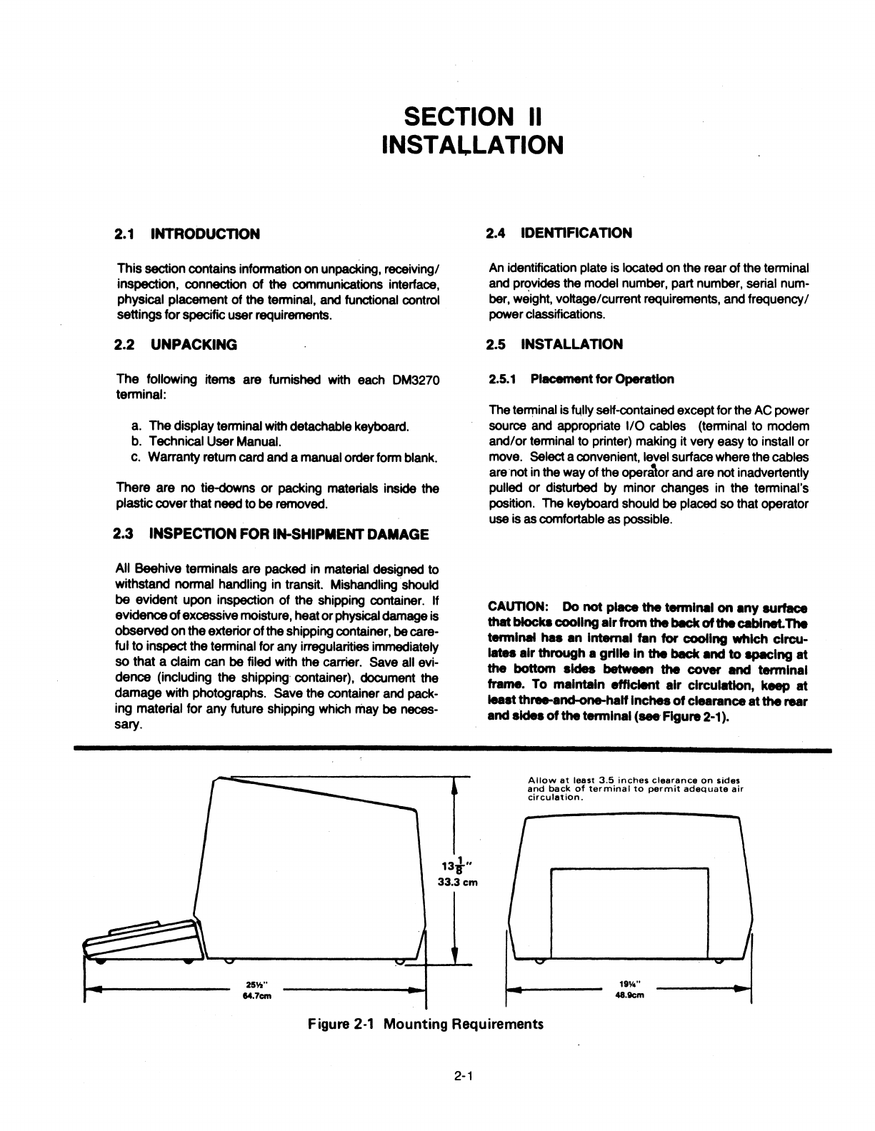
CAUTION: Do
not
place
the
termln11I
on
•ny surface
that
blocke
cooling
•Ir
from
the
bllck
of
the
Cllblnet.The
termlNll
hu
•n
lntern•I tan
for
cooling
which clrcu-
llltes
•Ir
through
a grille
In
the
bllck
Md
to spmclng
mt
the
bottom
sides between
the
cover llnd
terminal
frame. To
maintain
efficient air
clrcul.tlon,
keep at
least
three-and-one-haH
Inches
of
clearance
at
the
rear
andsides
of
the
termln11I
(seeFigure2-1).
Allow
at
least
3.5
inches
clearance
on
sides
and
back
of
terminal
to
permit
adequate
air
circulation.
Figure 2·1 Mounting Requirements
2-1

GROUN~.
I w
115
Volt
GROUND
230Volt
lnternetlonal RequhwMntPlug
Figure2·2
AC
Powerand Ground Connectors
2.5.2
AC
PowerConnection
The
terminal
isshipped
with
either
a 115or
230
volt
power
cord
and
a corresponding Internal power
transformer
con-
figuration.
Your
AC
power outlet must supply a voltage
within +
-10%
pf
115
or
230
volts(whiclMMfrisconfigured)
for
proper
operation.
The
grounding
conductors
indicated
in
Figura 2-2
provide
important electrical connections which should always
be
preserved
by
plugging .the terminal into a properly
grounded outlet or adapter. Grounding is vital
not
only
from
an
operator safety standpoint, but
also
to suppress
radio frequency/electromagnetic interference
(RFl/EMI)
and
drain
off
static electricity charges which
may
accumu-
late
and
impairdataintegrity.
Any
extension cord used to
provide
power
to
the terminal
must
be
three
wire
type
which preseives grounding in-
tegrity.
Its
wire
size
must
be
sufficient
to
insure
adherence
to
local
electricalcodes.
Table
2·1
Main Port Pin Assignments
PIN RS2320 DESCR. SIGNAL ASSIGNMENTS
NO.
DIRECTION
1
AA
Fr-
-
C.._,.
ground;
electrlc:8lly
bonded
lo
Ground
"-·
2
BA
T111111Nnlt
m.--oau.
Set
Pin2wlllbeInthe11M1k c:ondlllon
wtlh
Data no
outPut
elgnlll
3 BB
Receive
OM-Data
Set
Datafrom
hoet
Data
4
CA
Request
DM--Data
Set
a-
hi
during
............
;
drape
to
Send
lo
upon-...i1on.
5 CP
Clear
to
DM-DataSet
Whenhl,--IMlonle
.........
Send
When
held
lo,
--••Ion
..
~-
6 cc Data
Set
OM-Data
Set
~--•r-.ty.
Raady
7
AB
Signal
-
S-potentlal
•~ground
Ground
(pint).
15
DB
Tranamlt
'*-"Data
Set
Xl
T111111Nftlaalon
cloc:ll
from
modem.
Clock
17
DD
Receive
OM-Data
Set
Xl Receive
Clock
from
modem.
Clock
20
CD
Data
OU-Data
Set
Held
hi"'*'
Ille
..............
l'Mdy.
Terminal
Ready
.,_.,
2.5.3
Data
Interface
Connection
Signals
used
in communicating with the DM3270 conform
to
the
requirements
of
EIA specification RS232C. Inparti- .
cular,
output
voltagesswing from
-10V
to+
10V, while the
receivers presenta minimum of
3k
ohms impedanceto the
line.
The
input resistance is approximately 4k ohms. The
driver
circuits have acurrent limit
of
10
mA
on both
source
and
sink. All
data
source interconnections are
made
via
the
rear panel input/outputconnector (see Figure 2-3). A
25-pin
miniature
0-type
ITT
Cannonconnector (DM-258
or
equivalent) is used for connection to the computer. Pin
assignments
are
defined in Tables 2-1 and 2-2. Thecom-
municationsline
from
the
modem
connectstothemainport
and
theprinterconnects totheAUXport(printerport).
Table 2·2 PrinterPort Pin Assignments
PIN
~S232C
NO. DESCR. SIGNAL
DIRECTION ASSIGNMENTS
1
AA
Frame
-
Chaaala
ground;
elec:trlc:911y
bonmd
to
Ground
Ir•-·
2
BA
Receive
ou-Prlntlw
Data
received
from
printer.
Data
Du.!-Prtm.r
Transmit Data
output
lo
prlnt9r.
3 BB Data
4 CA
Request
OM-Printer
lg-
by
DM3270
to
Send
5 CB
Clear
OU-Prl-
"--Ina
hi
..
Ml
tllMe.
Send
6 cc Data
Set
~Prl-
~hl
..
.Ut"-.
Reedy
7
AB
Signal
-
Sa-
potential H
pin
1.
Ground
8
CF
Carrier
DM-Prlnter
"--Ina
hi
at
..
,...,...
Detect
11
Printer
DM-Prtm.r
'#1*1
hi,
prinWCM
._iwdmla.
Not
Busy
'#1*1
lo,~
labuay.
111
Prlnl9r
DM-Prl...,.
Sllme• Pin
11
20
CD
Not
euy!
Data
DM-Prlni.r
When
hi,
prlnl9r
la onllna.
Termin•I
When
lo,
pr..-
la
ollllne.
Raadv
2.5.4
PC
ao.rd-MountedControlSWltchH
Three switch blocks are mounted
on
the printed circuit
board.
Two
are
located
at
the
rear
of
the board
and
are
accessible for resetting through
an
external opening. The
otherswitch block is located
near
the
left rear
comer
of
the
board
and
can
be
reached
by
removing the cover.
These
switches
are
illustrated in Figure2-3.
2.6
INmAL
TURN-<>N
PROCEDURE
The proper
tum
on
procedure for the terminal is described
in Subhead 3.1.2.
2.7 REAR PANELSWITCH USE
The
operating configuration
of
the
DM3270
is
defined
by
rear panel and internal switch positions as described in

Figure2-3 and the remainderofthis subsection.
2.
7
.1
LCI -LowerCase lnhlbH
51-1
When LCI is
not
selected (S
1-1
down), alpha characters
are displayed in upper and lower case just as they are
entered in the display buffer. When LCI is selected
(S1-1
up), all lower case character codes are entered and dis-
played upper case characters. Changing the switch set-
tingonlyaffectsdataentered intothedisplaybufferafter
the
switch as been changed. Data already displayed is not
affected.
2.
7.2 Setting UpContention Protocol
(Point-to-Point)*
The
terminal may
Qe
configured in a contention protocol or
point-to-point mode (switched line, dial up). This protocol
allows the
host
to interact, by specific address, with up to
128lerminals. Setthe rear panel switches as follows:
1.
Set switch 4 of the internal switch block 3 (S3)
to
the
"on"
position (see Figure 2.3).
2.
To
set the terminal address, use the following chart
and setswitches2 through 8 on external switch S1to
reflectthe desired 3 digitterminal l.D. number.
Table 2-3 Contention Protocol (point-to-point)
TERMINAL SWITCH NUlll8ERS
l.D.NUMBER
2 3 4 5 a 7 •
000 OFF OFF OFF OFF OFF OFF OFF
001 OFF OFF OFF OFF OFF OFF
ON
002 OFF OFF OFF OFF OFF ON
.OFF
003
OFF OFF OFF OFF OFF
ON
ON
004 OFF OFF OFF OFF
ON
OFF OFF
005 OFF OFF OFF OFF
ON
OFF
ON
006
OFF OFF OFF OFF
ON ON
OFF
007 OFF OFF OFF OFF
ON
ON
ON
008 OFF OFF OFF ON OFF OFF OFF
009 OFF OFF OFF
ON
OFF OFF
ON
010 OFF OFF OFF
ON
OFF
ON
OFF
011 OFF OFF OFF
ON
OFF
ON ON
012 OFF OFF OFF
ON
ON OFF OFF
013 OFF OFF OFF
ON
ON
OFF
ON
014 OFF OFF OFF
ON
ON
ON
OFF
015 OFF OFF OFF
ON
ON. ON
ON
016 OFF OFF ON OFF OFF OFF OFF
017
OFF OFF ON OFF OFF OFF
ON
018 OFF OFF
ON
OFF OFF
ON
OFF
019 OFF OFF ON OFF OFF ON
ON
020 OFF OFF
ON
OFF ON OFF OFF
021 OFF OFF
ON
OFF
ON
OFF
ON
022 OFF OFF ON OFF ON
ON
OFF
023 OFF OFF
ON
OFF
ON
ON ON
024 OFF OFF ON ON OFF OFF OFF
025 OFF OFF ON ON OFF OFF
ON
026
OFF
OFF ON
ON
OFF ON OFF
027 OFF OFF ON
ON
OFF
ON
ON
028 OFF OFF ON
ON
ON
OFF OFF
029 OFF OFF
ON ON
ON
OFF
ON
030 OFF OFF ON
ON
ON
ON
OFF
031 OFF OFF ON
ON
ON ON ON
032 OFF
ON
OFF OFF OFF OFF OFF
033 OFF
ON
OFF OFF OFF OFF
ON
034 OFF ON OFF OFF OFF ON OFF
035 OFF
ON
OFF OFF OFF
ON
ON
036 OFF ON OFF OFF
ON
OFF OFF
037
OFF
ON
OFF OFF ON OFF
ON
038 OFF ON OFF OFF ON ON OFF
039 OFF ON OFF OFF
ON
ON
ON
040 OFF
ON
OFF ON OFF OFF OFF
041 OFF
ON
OFF
ON
OFF OFI"
ON
042 OFF
ON
OFF ON OFF ON OFF
043 OFF
ON
OFF
ON
OFF ON
ON
044 OFF
ON
OFF
ON
ON OFF OFF
045 OFF ON OFF ON ON
Oi'F
ON
2-3
TERMINAL
__
,j
l.D.NUMBER SWITCH NUMBERS
2 3 4 5 6 7
~-
--
----
---
046
OFF
ON
OFF ON
ON
ON
OFF
047 OFF ON OFF
ON
ON
ON
ON
048 OFF
ON ON
OFF OFF OFF
OFF
049 OFF ON ON OFF OFF OFF
ON
050
OFF ON ON OFF OFF
ON
OFF
051 OFF
ON
ON OFF OFF
ON ON
052 OFF
ON
ON
OFF ON OFF
OFF
053 OFF
ON
ON OFF ON OFF
ON
054 OFF ON ON OFF ON
ON
OFF
055 OFF ON ON OFF
ON ON
ON
056 OFF
ON
ON
ON
OFF OFF OFF
057 OFF
ON
ON ON OFF OFF
ON
058 OFF
ON ON ON
OFF
ON
OFF
059 OFF
ON
ON ON OFF
ON
ON
060 OFF ON ON
ON
ON
OFF
OFF
061 OFF ON
ON
ON
ON OFF
ON
062 OFF ON ON
ON
ON
ON
OFF
063 OFF ON
ON
ON ON
ON ON
064 ON OFF OFF OFF OFF OFF OFF
065 ON OFF OFF OFF OFF OFF
ON
066 ON OFF OFF OFF OFF
ON
OFF
067 ON OFF OFF OFF OFF
ON ON
068 ON OFF OFF OFF ON OFF
OFF
069 ON OFF OFF OFF ON OFF
ON
070
ON OFF OFF OFF
ON ON
OFF
071 ON OFF OFF OFF
ON
ON ON
072 ON OFF OFF ON OFF OFF
OFF
073 ON OFF OFF
ON
OFF OFF
ON
074 ON OFF OFF
ON
OFF
ON
OFF
075 ON OFF
OFF.
ON
OFF
ON ON
076 ON OFF OFF
ON
ON
OFF
OFF
077
ON OFF OFF
ON
ON
OFF
ON
078 ON OFF OFF
ON ON
ON
OFF
079
ON
OFF OFF
ON
ON
ON ON
080 ON OFF OFF
ON
OFF OFF
OFF
081 ON OFF ON OFF OFF OFF
ON
082 ON OFF ON OFF OFF
ON
OFF
083 ON OFF ON OFF OFF
ON
ON
084 ON OFF
ON
OFF ON OFF OFF
085 ON OFF ON OFF
ON
OFF
ON
086 ON OFF ON OFF
ON
ON
OFF
087
ON OFF
ON
OFF
ON ON
ON
088 ON OFF ON
ON
OFF OFF OFF
089 ON OFF ON ON OFF OFF
ON
090 ON OFF
ON ON
OFF
ON
OFF
091 ON OFF ON
ON
OFF
ON
ON
092 ON OFF
ON ON ON
OFF OFF
093 ON OFF ON
ON ON
OFF
ON
094 ON OFF
ON ON
ON
ON
OFF
095 ON OFF
ON
ON
ON
ON
ON
096 ON ON OFF OFF OFF OFF OFF
097 ON
ON
OFF OFF OFF OFF
ON
098 ON ON OFF OFF OFF
ON
OFF
099 ON
ON
OFF OFF OFF
ON ON
100 ON
ON
OFF OFF
ON
OFF
OFF
101
ON
ON
OFF OFF ON OFF
ON
102 ON
ON
OFF OFF ON
ON
OFF
103 ON ON OFF OFF ON
ON
ON
104 ON ON OFF
ON
OFF OFF OFF
105 ON ON OFF
ON
OFF OFF
ON
106 ON
ON
OFF
ON
OFF
ON
OFF
107 ON
ON
OFF
ON
OFF
ON
ON
108 ON
ON
OFF
ON ON
OFF
OFF
109 ON
ON
OFF
ON
ON OFF
ON
110 ON
ON
OFF
ON
ON
ON
OFF
111
ON
ON
OFF ON
ON ON
ON
!
112 ON
ON ON
OFF OFF OFF
OFF
113
ON
ON
ON
OFF OFF OFF
ON
114 ON ON
ON
OFF OFF
ON
OFF
115 ON ON
ON
OFF OFF
ON
ON
116 ON
ON ON
OFF ON OFF OFF
117 ON ON
ON
OFF ON
OFF
ON
118 ON ON
ON
OFF ON
ON
OFF
119 ON ON
ON
OFF ON
ON
ON
120
ON
ON
ON ON
OFF OFF
OFF
121
ON ON
ON ON
OFF OFF
ON
122 ON ON
ON ON
OFF
ON
OFF
123 ON
ON ON ON
OFF
ON
ON
124 ON
ON ON ON ON
OFF OFF
125 ON
ON ON ON
ON
OFF
ON
126 ON
ON
ON
ON ON
ON
OFF
127 ON
ON
ON
ON ON
ON ON
*NOTE: Disregard paragraphs 2.7.4, Printer Address and
2.7.5, DM3270 Control Unit Address when using 3275
point-to-point. Use these paragraphs when operating
in
3276 multipointonly.

S1-4 51-5 51-6 51-7
Down Down
Down Down
Down
Down Down
Down
Down Down
Down
Up
Down Down
Down
Up
Down Down
Up
Down
Down
Down
Up
Down
Down
Down
Up
Up
Down
Down
Up Up
Down
Up
Down Down
Down
Up
Down
Down
Down
Up
Down
Up
Down
Up
Down
Up
Down
Up Up
Down
Down
Up Up
Down
Down
Up
Up Up
Down
Up
Up Up
Up
Down
Down
Down
Up
Down
Down
Down
Up
Down
Down
Up
Up
Down
Down
Up
Up
Down
Up
Down
Up
Down
Up
Down
Up
Down
Up
lJp
Up
Down
Up
Up
Up
Up
Down
Down
Up Up
Down
Down
Up
Up
Down
Up
Up Up
Down
Up
Up Up Up
Down
Up Up
Up
Down
Up Up
Up Up
Up Up
Up Up
Table2-3 Control Unit
AddrMe
Chart
3278 ModeOnly
Control Unit
Control Unit
Code
(EBCDIC)
or
Device
110
Hex
51-8 Address Char. Code
Down
0
SP
40
Up
1 A
C1
Down
2 B
C2
Up
3 c
C3
Down
4 D
C4
Up
s E cs
Down
6 F
C6
Up
7 G
C7
Down
8 H
ca
Up
9 I
C9
Down
10
¢
4A
Up
11
48
Down
12
<
4C
Up
13
(
4D
Down
14
+
4E
Up
15
I
4F
I
Down
16
& 50
Up
17
J
D1
Down
18
K
D2
Up
19
L
D3
Down
20
M D4
Up
21
N
D5
Down
22
0
D6
Up
23
p
D7
Down
24
Q
08
Up
2S
R
09
Down
26
'
5A
Up
27
$
S8
Down
28
.
SC
Up
29
)
SD
Down
30
.
SE
Up
31
1
SF
Select Poll
1/0
Hex
Char. Code
-60
I
61
s
E2
T
E3
u
E4
v
ES
w
E6
x
E7
y
ES
z
E9
6A
. 68
O/o
6C
-
6D
>
6E
?
6F
0
FO
1
F1
2
F2
3
F3
4
F4
5
FS
6
F6
7
F7
8
F8
9
F9
7A
# 78
@
7C
7D
=
7E
..
7F

I\)
cJ,
PRINTER
SWITCH
Sl
-
1 l~ll
CASE
DISMlE ·w
OWIACll•
.-U'fl
~--
1 z J ..
-
z•a.urw
] - w
....
COll11IOl
11111'
0 I 1 J 4 S
(())
JO
JI
-
...............
,
.............
.
-
....
-
w..
•
..
...............
DltUPDllWl*W
DllUP
..
l
1
l
-
•
!
•
-
7
I
SWITCH
S2
PMITtR
CONTROL
-
......
IUSY
.......
ITIM:ll
....
"°"
--
l1't
... ...
...
...
..
..
..
..
... ...
..
..
... ...
..
..
...
..
...
..
...
..
...
..
PMfTtll
MUD
llATt
110
ISO
-
....
uoo
--
.....
... ... ... ...
..
..
..
..
...
...
.. ..
... ...
..
..
...
..
...
..
...
..
...
..
l'MITU
PAllTY
Mii
....,.
--
... ...
.. ..
...
..
...
..
SEE
OPERATORS
MANUAL
FOR
FURTHER
INFORMATION
ON
FUSE
DP
.0
1AMP
0
115V
W .5AMP
E
230V
OFF R
~
POWER
CORD
...............
........
.....
.
·1.·1.·:.·.·.::.·.·······
AUX
MAIN
Printer Port
EXTERNAL
SWITCHES
DM3270
0
©
CONT
SWITCH
S1
SWITCH
S2
011
II
II
BRT
12345678
1
2345678
INTERNALSWITCH
S3
ON SWITCH
Non Buffered Print Enable 1
Format
Local
Print 2
Dispaly Programmed
3'
for50Hz
3275 Point-to-point
4"
Not used 5
Must
be
on
6
Must
be
on
7
Not used B
OFF
Non Buffered Print Disable
IBM 3276 Local Print
Display Programmed
for60Hz
3276 Multipoint
Notused
Notused
ASCII
code
EBCDIC
code
HOST •NOTE:
Monitor
alignment
may
be
necesa.y
ii
thl•
ewltchla
c:Nnged.
"NOTE:
If
"on",
printer
addrnaing
will
no
longer
apply.
MODEM
Figure 2-3 Internal and External Switches
With
Communications
Hookup

2.7.3 Optional Beehive Prlnter(P1600)
A desk top serial printer for use as
an
IBM 3287 type
printing unit. This printer will print via the DM3270 control
unit datafrom thehost
or
directfrom the DM3270. Consult
the Printer Operator manual, sent with the printer, for fur-
ther installation instructions.
2.7.4 Printer
AddrHs
(S1-2, S1·3)*
These switches specify the address used by the host to
select the printer
when
in the 3276contention mode. The
addresscan
be
any number
from
1-4selected asfollows:
~ex
Device/ Code
1/0
S1-2 S1-3 Address Number Char
Down Down 1
C1
A
Down Up 2 C2 B
Up Oown 3 C3 c
Up Up 4
C4
D
2.
7.5
DM3270
Control
Unit
Address*
S1-4, S1-5, S1-8, S1-7, S1-8
This is the address by which. the DM3270 is polled
or
selected
by
the host when in 3276 contention mode. The
address can
be
any number in a program from 0-31
selected
from
Table 2-3. Also shown are the actual
110
charaters transmitted over the communications line for
each control unit address
and
for each printer address.
I/
0 character (")istransmitted asthe deviceaddress during
a general poll operation.
2.7.6
Printer
FlowControlS2-1, S2-2, S2-3
Severaltypes of printers can
be
attachedto the printerport
of the DM3270. These printers use different means for
signaling the DM3270 that the printer
is
busy and cannot
accept data. Each printer must provide Data Terminal
Ready (OTA) on
Pi_n
20.
S2-1 $2-2 $2-3 Flow Control Type
and PrinterType
Down Down Down No Printerattached
Down Down Up Pin
11/19
=Ready
Down Up Down Pin
11/19
=Busy
down Up Up Pin
11/19
=Reverse
Channel
Up Down Down
ETX/ACK
Up Down Up XON/OFF
Up Up Down ACK/NAK
Up Up Up
TTY
*NOTE:
Disregard paragraphs 2.7.4, Printer Address
· and
2.
7.5, DM3270Control UnitAddress when using3275
point-to-point. Use these paragraphs when operating in
3276multipointonly.
2.7.7
Printer
Speed
S2-4, S2-5, S2-6
These switches allow the userto match
the
terminal baud
rate (through the AUX I printer port) with the printer baud
rate.
S2-4 $2-5 $2-6 Baud Rate
Down Down Down 110 (2stop bits)
Down Down Up 150
(1
stop bit)
Down Up Down 300 (1stop bit)
Down Up Up 600
(1
stopbit)
Up Down
Down
1200
(1
stop bit)
Up
Down Up 2400
(1
stopbit)
Up Up
Down
4800
(1
stop bit)
Up Up Up
9600
(1
stopbit)
2.
7.8
Printer
Parity
S2-7, S2-8
These switches match the parity
of
the terminal with the
parity of the printer. The switches have the following
definitions:
$2-7 S2-8
Down Down
Down Up
Up Down
Up Up
2.8 INTERNAL
SWITCH
USE
S3-1,S3-2,S3-3
Parity
Even
Space
Odd
Marl<
lntemalswitch S3-1 isusedtospecify whetherthe DM3270
will support the buffered or non-buffered print command.
The buffer printer operation requires a unique printer ad-
dress, where the non-buffered print uses the CRT as the
buffer.
lntemal switch S3-2 is used to provide additional printer
support. With thisswitch in theonposition, a local printwill
notcompress nulllines
and
willdoaform feed aftertheprint
is completed. This
option
allows information that is dis-
playedon
the
screento
be
formattedonforms using a local
print
..
lntemal switch
83-3
specifies the frequency of the power
source.
The display should match the power line fre-
quency
to
avoidbeat interference.
Switch 4 is
"on"
for3275 point-to-point protocol (see Sub-
head
2.7.2) and "off"
for
3276 multipoint protoool (see
Subhead2.7.4
and
2.7.5).
2-6
Switches 6
and.
7 must always
be
on
and should not
be
changed since
they
control the
reverse
videoand highlight
features.

SECTION Ill
OPERATION
3.1
BASIC OPERATION
Thissection providesdetailed operating instructionsforthe
DM3270 Control Unit Display Station. Subhead
3.
1 pro-
vides a description ofthe basic operating environment and
explains
how
to
tum
on the terminal. Subhead 3.2 gives a
detailed description
of
the operation of the display and
Subhead3.3describes
how
tooperatethekeyboard. Sub-
head 3.4 describes the operation of the printer, and Sub-
head 3.5 describes the self-confidence test provided with
theterminal.
3.
1.1
Operating Environment
The DM3270 is a remote terminal operating
in
a polled
communications environment where operation may be
over either leased/dedicated communication lines
or
through a display facility. For this use, the terminal does
not communicate with the host computer as each key on
the keyboard is depressed. Instead, the operator enters a
logical set of data into the terminal's display buffer
in
re-
sponse to a request from a host program and then trans-
mits all the datatothe hostas a single message.
A logical set
of
data could consist
of
several paragraphs of
a document being edited (unformatted data),
it
could be
several fields of data entered
in
response to a formatted
display produced by a host application program,
or
it could
be the selection of an item from a displayed menu. When
the requested data has been entered, the operator uses
one
of
the program attention keys to tell the terminal to
transmit data to the host. At the next poll or request from
the host for a data transmission, the terminal's display
buffer is transmitted to the host. The operator then waits
while the host program processes the entered data and
generates a response which is usually displayed on the
screen. The response may include a request for more
data. A typical application will include a series of such
operations as has just been described.
The
display screen keeps the operator informed on the
state
of
the terminal. The first 24 linesshowthe contents
of
thedisplaybuffer. Any changein the contents ofthe buffer,
eitherbytheoperator (through the keyboard) orby the host
is immediately shown on the display. The 25th line of the
display is a status line which informs the operator of all
otheraspects of theterminal'soperation. Forexample, the
operator can tell if the terminal is being polled
by
the host,
whetheror not the terminal is transmitting
or
receiving data
from the host, the status of the printer, whether
or
not the
keyboard is enabled and the type of field into which data is
currentlybeing entered. Subhead 3.2describesthestatus
line display and its operation.
Keyboard operation is simple and straightforward. Any
typist can master the keyboard, which bears a close re-
3-1
semblance to the standard typewriter. The few additional
keys function as operator-oriented convenience features
and selector switches for the terminal's operating modes.
Subhead 3.3 describes in detail how to operate the key-
board.
The printer (if attached)
is
shared by the terminal operator
and the host. The operator can request a print out of the
terminals's display buffer and the host can independently
transmit data to the terminal for printing without disturbing
the display. Subhead 3.4 describes printer operation
in
detail.
3.1.2 Turn-On Procedure
Before the DM3270 is used,
it
must be properly installed
and setup
in
accordance with Section 2 of this manual.
The installationshould bedoneonlyby qualified personnel.
An identification plate located on the rear panel of the
terminal specifies its electrical powerrequirements. When
moving the terminal to an alternate operating position,
make sure that the selected power outlet
is
properly
grounded and supplies the correct operating voltage and
frequency. Gettechnical assistance, if necessary,
in
mak-
ing this determination.
Theproperturn-on procedurefortheterminal
is
as follows:
a.
Setthe rear panel POWER
ON/OFF
switch to ON (see
Figure 2-3; allow a warm-up period of about a minute
and ensure that the cursor and status line have ap-
peared on the screen. If both the cursor and status
line do not appear, check the brightness and contrast
adjustments as explained
in
b.
b.
Tum
the brightness control (BAT located on the rear
panel; see Figure 2-3, if necessary) until a raster
is
faintly visible on the screen. Enter several characters
on the screen. Reduce the brightness until the back-
ground raster (diagonal lines) is extinguished. Adjust
the contrast control (CONT on the rear panel) until the
characters are easily read in the available room light.
The adjustment can best be made when characters are
displayed
in
both normal and bright intensity. Such a
display must becalled up from the host CPU.
c.
Any time power
is
initially applied to the DM3270,
it
performs a display memory test and a terminal opera-
tion test. Because of the CRT warmup time, there
is
no
visible effect on the screen. If the unit
is
turned off and
back on, a slight display flicker occurs while the test
is
run. When the self-test is successfully completed,
"Idle" appears on the status line.
In
the event of a test
failure, error messages (see Subhead 3.2.5) will appear
on
the
screen. The self-test may also
be
initiated
by
pressing
the
TEST
key.
3.1.3 Rear Pmwl
Switches
Switch blocks 1
and
2
(S
1and
S2)
onthe rear panel select
certain operating features of the DM3270.
There
are a
total of 16 miniature switches, eight on
each
switch
block.
Most rear panel switches
require
no
operator attention
because
they must
be
properly
set
when the terminal is
installed.
Subhead
2.
7describes
how
to changeaswitch.
3.1.4 AudibleAlarm
The audible alarm capability within
the
terminal alerts
the
operatorwhenerrorconditions
arise.
Thefollowing
condi-
tions soundtheaudiblealarm.
1.
At
the
start of
the
self-confidence test.
2. An invalid
keyboard
entry.
3. Thehostcomputerwantsto alert theoperator.
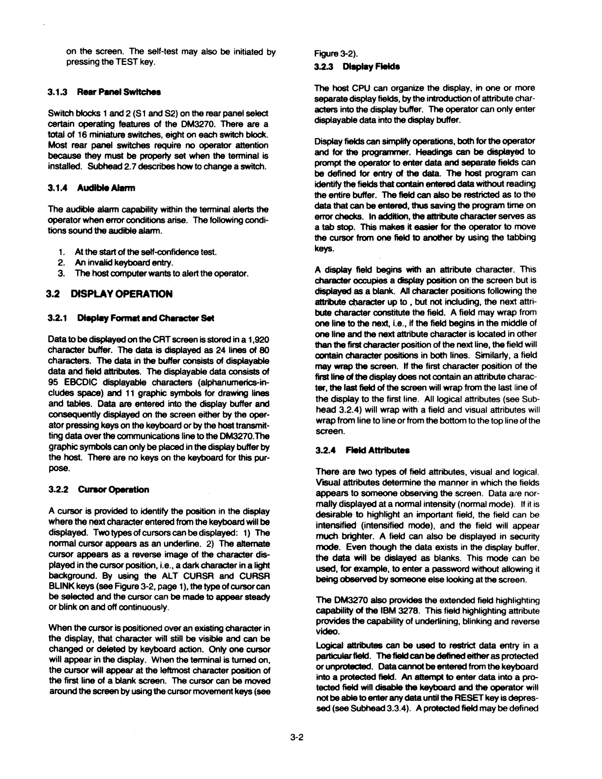
3.2 DISPLAYOPERATION
3.2.1 Dl8plllyFormat
Md
Ctt..:ter
SM
Datato
be
displayed
on
the
CRT
screen
isstored in a1,920
character buffer. The
data
is displayed as 24 lines of
80
characters. The
data
in the buffer
consists
of displayable
data
and
field attributes. Thedisplayable
data
consists of
95 EBCDIC displayable characters (alphanumerics-in-
cludes
space)
and
11
graphic symbols for drawing lines
and tables. Data are entered into the display buffer
and
consequently
displayed
on
the
screen either
by
the
oper-
ator
pressing
keyson
the
keyboard or
by
thehost
transmit-
ting
data
over
the
communications
lineto
the
DM3270.The
graphicsymbolscanonly
be
placed
in
the
displaybuffer
by
the
host.
There are no keys on the keyboard for this pur-
pose.
3.2.2 CUraorOperation
A cursor is provided to identify the position in the display
where
the
nextcharacterentered
from
thekeyboard
will
be
displayed. Twotypesofcursorscanbedisplayed: 1) The
normal cursor appears
as
an underline.
2)
The
altemate
cursor appears
as
a reverse image of
the
character dis-
played in
the
cursor
position, i.e.,a darkcharacter ina light
background.
By
using the
ALT
CURSR
and
CURSR
BLINKkeys (see Figure3-2, page
1),
thetypeofcursorcan
be selected and the cursor can
be
madeto appear steady
orblink
on
and
offcontinuously.
When
the
cursor ispositioned overan existingcharacter in
the display, that character will
still
be
visible
and
can be
changed or deleted
by
keyboard action. Only one cursor
will appear in
the
display. When
the
terminal is turned
on,
the cursor will appear at
the
leftmost character position of
the
first line of a
blank
screen. The cursor can
be
moved
aroundthescreen
by
usingthecursormovementkeys (see
3-2
Figure3-2).
3.2.3 DleplayFlelds
The
host
CPU can organize
the
display, in one
or
more
separatedisplayfields,
by
the
introductionofattribute char-
acters into the display buffer. Theoperator can only enter
displayabledatainto
the
display buffer.
Displayfields
can
simplifyoperations, bolh
for
theoperator
and
for
1he
programmer.
Headings can be disptayed to
prompt the operatorto enter
data
and
separate
fields can
be defined for entry of the
data.
The
host
program
can
identify
the
fields thatcontain
ent8l'8d
data
without reading
the
entire buffer. The field can also
be
restricted as tothe
data
thatcanbeentered, thus
saving
the
program time on
enorchecks. In addition,theattributecharacterserves
as
a tab stop. This
makes
it easier for
the
operator to
move
the cursor
from
one
field
to anolher by
using
the
tabbing
keys.
A display field begins
with
an attribute character. This
characleroccupies a display position on the screen but
is
displayed
as
a blank.
All
characler positions following
th~
atlribute
cbaracter
up to , but
not
including,
the
next attri-
bute
character constitute the
field.
A field may wrap from
one
line to
the
next, i.e., if the
field
begins in the middle of
one
line and
the
nextattribute character is located inother
thanthefirst character position
of
the next line,
the
field will
contain
character positions
in
bolh
lines.
Similarly, a field
may
wrap the
screen.
H
the
first character position of
the
firstlineof
the
display
does
notcontainan attributecharac-
ter,
the last field of
the
screen
will
wrapfrom
the
last line
of
the display to
the
first line. All logical attributes (see Sub·
head 3.2.4) will wrap with a field and visual attributes will
wrapfrom lineto lineorfrom thebottomto thetoplineofthe
screen.
3.2.4 FieldAttributes
There are two types of
field
attributes, visual and logical.
Vasual
attributes determine
the
manfl8r in which the fields
appears
to
someone observing
the
screen. Data are nor-
mallydisplayedata nonnal intensity (normal mode). If it
is
desirable to highlight an important field, the field can
be
intensified (intensified mode), and
the
field will appear
much brighter. A field can also be displayed in security
mode. Even though the data exists
in
the display buffer.
the data
witl
be dislayed
as
blanks. This
mode
can
be
used,
tor
example, toenter a
password
without allowing it
being
observed
by
someone
else
looking at
the
screen.
The DM3270 also provides
the
extended field highlighting
capability of
the
IBM 3278. This field highlighting attribute
provides
thecapability of underlining, blinking and reverse
video.
Logical attributes can
be
used
to
restrict data
entry
in a
particularfield. Thefleldcanbed8ftnedeither
as
protected
orunprotecl8d. Data
cannot
be
enteredfrom
the
keyboard
into a protected field. An attemptto enter datainto a pro-
tected
field
will
disable
the
keyboard and the operatorwill
not
be
abletoenter
any
data
untiltheRESET
key
isdepres-
sed
(see Subhead3.3.4). A protectedfield maybedefined

as
an
automaticskipfield. Thisattributecauses thecursor
to
skip
to
the
next unprotected field when it enters an
automatic skip field, which again makes it easier for the
operator
to
move
from one datafield
to
another.
Ifa field isunprotected, it canalso
be
definedasalphameric
or
numeric.
Any
displayablecharactercan
be
entered into
an
alphamericfield. Onlynumericdatacan beenteredinto
a numericfield (see Subhead 3.3.4). Again, an attemptto
enter
invalid data into a numeric field will disable the key-
board.
Any
displayed field
niay
be
given the selector light pen
detectable attribute.This attribute allows the field
to
be
selected
for
transmission
to
the host
by
operating the
CURSR
SET
key. This feature allows
the
programmer
to
restrict
the
amount
of data that must
be
transmitted to the
host.
3.2.5 Statue Une
The
statuslineoccupies
the
25thlineofthedisplay. Itisnot
accessible
to
the
operator
or
the host. It isonly accessible
to
the
DM3270
for the display
of
current status informa-
tion. Normal status indicationsare
display~
as darkchar-
acters in a light background. Error indications can be dis-
played in a blinking mode. Thestatus line contains 9 fields,
A -
I,
spaced sequentially across the line. Each field is
separated from the next field by one character position
displayed as a blank in normal video mode (dark back-
ground). Each field is discussed in Figure 3-1.
3.2.6 LowerCase
Inhibit
(LCI)
LCI
mode
allows the operator to limit the display to upper
case
characters only. When the LCI switch is
in
the inhibit
position (see Figure 2-3), all new alphabetic character
codes
entered intothe display buffer, eitherfrom the
1/0
or
the
keyboard, are stored and displayed as upper case
characters. When the LCI switch is changed to the non-
inhibit position, new alphabetic character codes entered
are stored and displayed in theirnatural mode (as upperor
lowercase characters). When the switch is changed back
and forth from
one
position to another, previous data en-
tered
on
the
screen are not updated by the switch.
3.3 KEYBOARD OPERATION
The
keyboard enables the operator to change, edit, or
~-A
_
__.I
[D
01
..._
_o
___.I
.___I
_E
___.I
.__I
_F_·
_l
.__I
_G
__
l
.._I
_H
_
1 __.
Field A
lndic.te•
wh91Mrtn.
k9ybo9rd
I•
lnhlb!Md
or
not.
Th91M9Mg9
"Input
lnhiblt9CI"
will
b9
di91>layed
wi.n.v.r
t"9
.,,,.,.ior
ainnot
key
In
•ny
claUI.
S..
SubhHd
3.3.3
for
t"9
•lluatloM
lhllt
wlll
ceu•
thla
!MaNge
end
how
to
clNr
11.
FieldB
lndlcetee
tn.
.-
of
the
tenninel
in
communiceting
with
t"9
ho•t.
TM
1MaNge9
that
cen
b9
diepieyed In thia lleld
.,.
••
followa:
The
t•nninel
I•
In
an
Idle
atete. Reier
to
the
poll
lleld
of
IDLE
the
•tetu•
HM
(Fleld I)
to
-
II
t"9
tenninei
I•
b9ing
polled
by
the
hMt.
Thi•
I•
theateteIn
which
t"9
.,,,.,.ior
c.n
enter
d8te.
ENTER
SYSTEM
TEXT
NOTE:
TM
ENTER
key
h
..
-
depl9eud
end
the
termlnel
I•
either
eweltlng
•
poll
or
tr•nmmltling
text
to
the
ho9t. Th9
keyboenl
I•
dl•bled.
TM
tennlnel
h••
recel-
en
acknowllldge
for
the
lut
entry
and
the
•Y•tem
I•
currently
procwelng
the
text
rnnuge.TM
keyboenl
I•
d._.
The
termln•I
h
..
recelv9CI •
•lllrt
ul
text
cherec:ter (STX)
and
I•
.--lvlng
text.
Thi•
IM9Ull9
wlll
b9
diepieyed
until
the
ecknowiedge
hH
been
unt
to
the
ho9t. Th9
keyboerd
I•
dlubled.
If
during any
of
these operations a nagative acknowledge
(NAK), a retransmit request
(ENO)
or
a time-out
is
exper-
ienced, this field willblink.
.............
Field C
lndlc-the
p,...,,.,.or-of
the
Delil
Set
Reedy
•ignel
from
the
modem. Th9 lleld wfll
lllw11Y•
contein
the
rnnuge
"OSR".
II
the
DSR
•ignei
la
Pl998ftt,
the
rnnuge
wtll
b9
dl91>leyed
81
normel
lnten•lty
and
non-
bllnk
mode.
II
the
DSR
•lgnei
I•
not
pruent,
the
,,__
uge
will
blink
et
bright
lnten•lty.
Field D
•
.
lndlc.tn
the
type
of
llltrlbute
that
I•
controlling
the
fieldIn
which
the
curaor
I•
loceted.
Th9
poHlble,,,.....
al9
••fol._.:
•
•
•
•
ALPHA
Any
eiphanumeric
ch•-
c.n
b9
enter9CI.
:
NUM
Only
numeric
dlllll
(0-9,.,-,
or
DUP)
ain
b9enlel9d.
•
: PROTECT
No
entry
mey
b9
...-
in thlafield.
:ATTRIBUTE
:
NO
TE:
II any invalid entry
is
made, the.keyhoard will
be
disabled:.
: field D will blink,
and
field A will display ··input
lnh1b1ted.
:
The
keyboard will remain disabled until RESET key
is
~•••••••••••P,,~essed.
Field E
lndlctllas
whether
or
not
either
of
the
SHIFT
k•y•
is
depl9eud
or
the
SHIFT LOCK key
Is
lock9CI.
This
flekl
will
be
blank
when
none
of
the
keys
Is
c1ep
..
.-.
The
field
will
dl•pley
"SHIFT'
when
either
of
theSHIFT keys
I•
ctepl9eud
or
the
SHIFT LOCK
kliy
I•
In
the
locked
poaltlon.
Field F
Indicates
whether
or
not
the termlnel
Is
In
lnurt
mode.
The me11UQ9
"ln•rt"
will
b9
dl91>lay9CI
when
the
oper-
ator
dap19-
the INSERT key. Thia field
wlll
be
c
...
red
when
the
keyboenl
is
19Mt.
.
•
I
I
•
•
I
I
I
•
I
•
NOTE:
Ifthe
operator
tries to entermoredata mto a field than
it
can
hold, the keyboard will
be
disabled. Field F will blink and
field A will display "Input Inhibit."
The
keyboard wlil re-
1 main disableduntil reset.
.,
...........
.
Field G
lndictlles
the
status
of
the
printer.
The
198dy
•lgnel
I•
Data Termi-
nal
Ra9Cly
(DSR). Th9
printer
does
not
haveany
l99dy
signal,
therefol9,
the
printer
la always
•••umad
1911dy.
The
,,__
•118•
thtll
c.n
b9
dl91>lay9CI
In
thl•
field
a19:
PRNTRCHK
BLANK
PRNTRRDY
The
tennlnel
is
not
19e9ivlng a
l99dy
aignal
from
the
printer.
The
terminal
ls
19C9Mnga
1911dy
aignal
lrom
theprinter.
PRNTRBSY
•.........•.....
The
printer
is
procesalng
a
print
raqu..t.
Field H
Re•rv9CI
for
futu19 expenalon.
Field I
This
field
dl91>lays a
polling
indicator
while the terminal io being
poll9CI. Thefield
I•
blank
when
the
tennlnel
I•
not being polled.
Figure
3-1
Status Line Messagesand Field Descriptions
3-3

create character displays and transmit them to the host
computer or to the local printer. Figure 3-2 shows the
keyboard layout and gives a functional description
of
each
key.
The keyboard looks very much like a typewriter keyboard.
The keys in the center produce the alphabetic characters,
numeric characters, punctuation marks and special sym-
bols. These are displayable characters (alphamerics).
Surroundingthese keys arethespecial function keyswhich
are used to perform control functions. To the far right is a
numeric pad which is convenient to use in dataentry appli-
cations and is also used in special function operations.
3.3.1
KeyboardModes
The keyboard operates in 3 modes, unshifted, shifted, and
alter. Each mode provides a different interpretation of
some of the keys and extends the numberof key functions
without requiring an excessive number of keys. Each key
is labeled to indicate the function
it
performs in each
mode. The symbols on the top face of the key indicatethe
function performed
in
unshifted mode (lower symbol) and
the shifted mode (upper symbol). For example, the key
containing the 2 and @ acts as a2 in unshifted mode and a
@ in shifted mode. The symbol on the front face ofthe key
indicates the function performed in alter mode. For ex-
ample, the 2 key acts as a PROGRAM FUNCTION KEY 2
when in altermode.
The shifted mode is selected by depressing either one of
the SHIFTkeys marked with the 0 symbol
or
bypressing
the SHIFT LOCK key marked with the @ symbol. The
SHIFT keys are active only while depressed. Releasing
them returns the keyboard to the unshifted mode. The
SHIFT LOCK key also becomes active when depressed
and remains active until a SHIFT key is again depressed.
The shifted status ofthe keyboard is indicated in the status
line (see Figure 3-1).
The alter mode is selected by depressing and holding the
ALT key while pressing one of the other keys. The alter
mode is used mainly to activate special function keys that
might have serious consequences if activated accidently,
e.g., the CLEAR key which would clearthedisplay buffer.
3.3.2 TypamatlcOperation
Normally, when a key is pressed,
it
will only perform its
intended operation once. Some keys will repeat their op-
eration continuously aslong as they are held down. This is
called typamatic operation. All alphamerickeys operate in
thismanner. Thespecial function keysthathavetypamatic
operation are identified in Figure 3-2.
ihe
repeat rate is 10
characters persecond.
3.3.3 Keyboard Disable (InputInhibit)
Certain conditions disable the keyboard and prevent fur-
therentry by
the
operator. This condition is indicatedbyan ·
"Input Inhibit" message in the status line and may sound
the audible alarm. See Figure
3-1
and CLICKkey descrip-
tion in Figure 3-2, page
2.
The conditions that disable the
keyboard are listed below. Conditions
4,
5,
and 6 cause
the audible alarm to sound.
1.
Operation
of
any program attention key.
2. A host-initiated 1/0 operation addressed to the
terminal.
3. An operator initiated print operation, during the
transferof the display buffer to the printerbuffer. If
the
printer buffer is full, the transfer cannot take
place, so the keyboard will bedisabled until the full
condition goes away.
4. Operation
of
any alphameric key or of the DUP,
FIELD MARK, ERASE EOF, ordelete
key(/),
when
the
cursor is in a protected field
or
in a field-attribute
location.
5.
Operation
of
any alphameric key not included in the
numeric grouping when the cursor is in a numeric
field.
6. Anattempt is made to insertdatainto a full field.
The
keyboard disable condition can be cleared by the
following.
1.
Pressing the RESET key for conditions
4,
5,
and 6
above.
3-4
2. Pressing DEV CNCL for printer busy conditions
(condition 3).
3. Host initiated 1/0will be reset by specific command
from the host. Condition 1will normally be reset in
this manneralso.
3.3.4 AlphamerlcData Entry
Keyboard entry
of
an alphameric character into the display
bufferoccurs atthe cursor location. An attempttoenter
an
alphameric character into a protected data field or into
an
attributecharacterlocation will be blocked. Successfulkey-
board entry
of
the alphameric character causes the cursor
to advance to the next character location within the unpro-
tected data field. If the cursor advanced to the right-most
characterposition on the line, it automatically moves to the
first character position on the following line.
If the cursor, after advancing, is at an attribute character
location, it advances to the first character position
of
the
field defined by
the
attribute character.
If,
however, the
field has been defined as an AUTO SKIP field, the cursor
skips to
the
first character position
of
the next unprotected
field,
or
if there are
no
unprotected character locations in
the buffer, tothe first character position in the buffer.
In
a formatted buffer, attempting to entera character into a
field invokesseveral tests on that field. First, the field
must
be defined as unprotected. Second, if the field is defined
asa numericfield,
the
characterbeing enteredmustbe
one
ofthe following:
0123456789.-DUP
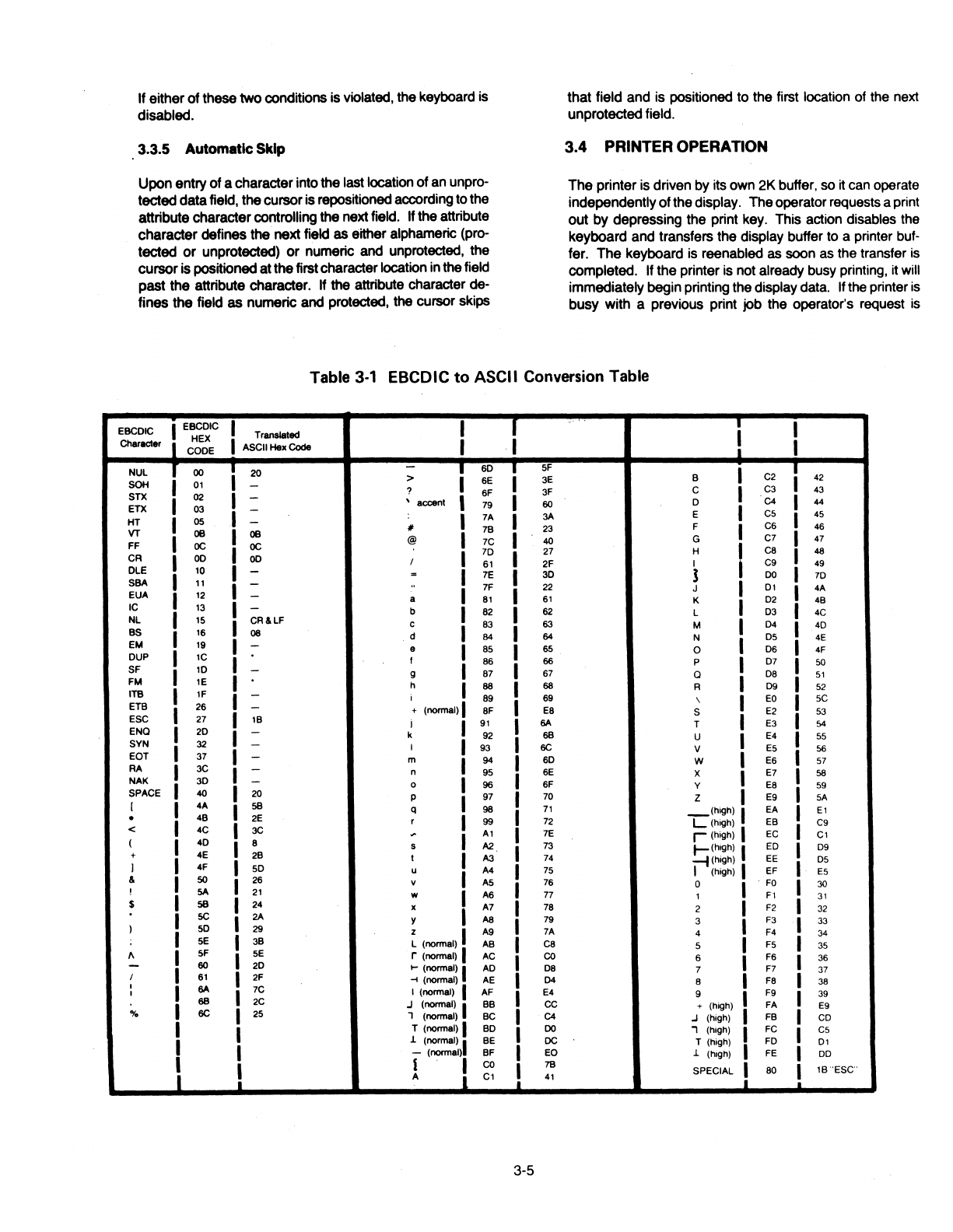
If either
of
these two conditions is violated, the keyboard is
disabled.
3.3.5 Automatic Skip
Upon entry
of
a characterintothe last location of an unpro-
tecteddatafield, thecursoris repositioned accordingto the
attribute charactercontrolling the next field. If the attribute
character defines the next field as either alphameric (pro-
tected
or
unprotected)
or
numeric and unprotected, the
cursoris positioned atthefirstcharacter location inthefield
past the attribute character. If the attribute character de-
fines the field
as
numeric and protected, the cursor skips
that field and is positioned to the first location of the next
unprotectedfield.
3.4 PRINTER OPERATION
The printer is driven by its own 2K buffer, so it can operate
independentlyofthedisplay. Theoperatorrequests aprint
out by depressing the print key. This action disables the
keyboard and transfers the display buffer to a printer buf-
fer.
The
keyboard
is
reenabled as soon as the transfer
is
completed. If the printer is not already busy printing, it will
immediately beginprinting the display data. Ifthe printer
is
busy with a previous print job the operator's request
is
Table
3-1
EBCDIC
to
ASCII Conversion Table
.,..
I I T T I
EBCDIC
I
EBCDIC
Translated
Character i HEX I ASCII
Hex
Code I I
CODE
.i
NUL
T ()() i
20
T
so
T
SF
I T
> 6E 3E B C2 42
SOH
01
-?
SF
3F c I C3 43
STX
02 I -' accent
60
D C4 I 44
79 I
ETX
03
I -
3A
E
cs
I
4S
7A
HT
OS
-
II
23 F I
cs
46
VT
OB
I 7B I
OB
@ 40 G C7 47
FF
oc oc
7C I
I
7D
27
H
ca
I 48
CR
OD
OD
I
S1
2F
I C9 49
OLE
10
-= 7E
30
J
DO
I
70
SBA
11
-
..
7F 22 J 01 I 4A
EUA
12
-a
81
S1
K
02
4B
IC
13
-b 82
S2
L D3 I 4C
NL
1S
CR&LF
c 83 63 M D4 I 4D
BS
16
08 d 84 64 N
DS
4E
EM
19
-9
as
65 0 D6 I 4F
DUP
1C f 86 66 p D7 I 50
SF
10
-g 87 67 Q
DB
S1
FM
1E
h 88 68 A D9 I
S2
ITB
1F
-I 89
S9
\
EO
SC
ETB
2S
-+ (normal)
SF
ES
s E2 53
ESC
27 1B I
91
I
6A
T E3
54
ENO
20
-k 92
68
u E4
SS
SYN
32 -I 93 6C v
ES
56
EOT
37 -m 94 6D w E6
S7
RA
3C -n
9S
6E x E7 58
NAK
3D -0 96
SF
y
EB
59
SPACE
40 20 p 97 70 z E9
SA
[ I 4A
SB
q 98
71
_(high)
EA
E1
• 4B 2E r 99 72
L(high)
EB C9
< 4C 3C
~
A1
7E
r<high)
EC
C1
(
4D
8 s
A2
73
t-<h1gh)
I ED D9
+ 4E 2B t A3 74
~(high)
EE
DS
J
4F
SD
u A4
7S
I (high) EF
ES
&
so
2S
v
AS
7S
0
FO
30
!
SA
21
w
AS
77 1
F1
31
$
SB
24 x A7 78 2 F2 32
SC I
2A
y
AS
79 3 F3 33
)
so
29 z
A9
7A 4 F4 34
SE
I 3B L (normal) AB
ca
5 F5 35
f\
SF I
SE
r (normal) AC
co
s F6 36
-60 2D
t-
(normal) AD D8 7 F7 37
I
S1
I 2F
~(normal)
AE D4 8 F8 38
I
6A
7C F9
I I I (normal) AF E4 9 39
68
2C
.J
(normal) BB cc + (high) FA E9
o/o
6C I 25 1 (normal) BC C4
.J
(high) FB CD
I T (normal) BD
DO
, (high) FC cs
.I.
(normal) BE
DC
T (high) FD
D1
I -(normal) BF
EO
.I.
(high) FE DD
J l l
co
78
SPECIAL
80 1B
'ESC'
i A
C1
i
41
...i
_i
3-5

queued and will start as soon
as
the previous job
is
fin-
ished. The keyboard
is
disabled
and
the display buffer
is
copied to the printer buffer
as
space becomes available.
When all the displaydata has been copied, the keyboard is
enabled again. Asecond printrequest could
be
entered
by
the operator before the first one completes printing. But
the display buffercannot
be
transferred to the printerbuffer
until the previous job has printed enough data to release
sufficientspace
in
the printerbuffertohold the
new
display
data.
All
buffers hold 2056 characters, but some of the
displaydata (security fields
and
null lines) may
be
transfer-
red
on
agiven printrequest. The keyboard will
be
disabled
until all the display data
has
been transferred to the printer
buffer.
The
status line indicates the printer status
in
field G (see
Figure
3-1).
A blank status indicates the printer
is
not
ready.
This
could indicate conditions such as a nonexis-
tent printer, a malfunctioning printer, the printer is out of
paper, the printer has been deselected or perhaps other
conditions. The operator will have to check the printer to
determine its status. A
PRNTR
ADY status indicates the
printer
is
ready foraprint request. When theprinterbegins
printing,
PRNTR
BSY
is
displayed until all the data in the
printerbuffer is printed.
3.5 SELF-CONRDENCETEST
The DM3270terminal incorporates abasicself-confidence
test to insure that the terminal is working correctly.·
The
self-test
is
invoked when the terminal is powered on or
when
the operator depresses the TEST key. When
the
self-test
is
completed, the terminal
is
initialized with a clear
screen
and
enters the idle mode.
The self-test begins
by
sounding the audible alarm
and
then tests various hardware components of the terminal.
Two
types
of
errors are detected: fatal and nonfatal. An
error
is
fatal
when
itoccurs
in
the
RAM
memory required by
theself-test (address 8700-87FF
Hex)
orif it is reasonably
certain that
the
CRT display will not work. When a fatal
error
is
detected, the audible alarm will
be
sounded 3times
and the terminal will stop functioning.
The
temJinal
can
only
be
restaffed again
by
turning the
power
off
and
on.
3-6
Each nonfatal error
is
reported
by
displaying a unique
number or letter code on the display screen starting
at
the
Home position. The nonfatal errors
and
their letter codes
are listed
in
Table
3-2.
The DM3270 provides line monitoring capabilities (monitor
mode) which displays all data including control characters
as they are received or transmitted. The DM3270 usually
displays only text addressed to the receiving terminal.
In
monitor mode, all data that are received
from
the host
is
displayed
in
normal video and all data that are sent to
the
host, including
pads,
will
be
displayed
in
reverse video.
The operator may enter monitor mode by depressing
the
ALT, SHIFT, andTESTkeys simultaneously.
Table 3-2 Self Confidence Test Error Descriptions
Error
Code ErrorDescription
np
CRC
ct.ck
error
for
ROii
chip(•)
'n',
....,.n
=
1,Z.3.4.and/or5
R RAM memory
hH
failed
A Printer
port
blludrate
cloell
write/reed
..,.,r
a Main port USARTwrlta/19aderror
c':
Keyboard
acannar(8255) wrlte/rellderror
D Printer
port
Interrupterror
H Printer
port
timeout
error
I Printer
port
receivererror(parity, overrun, framing)
J Printer
port
racalvlld
data
error
K Video
clock
rat•
error
L Printer
port
beud rate
error

CURSR
SEL
!also see
Note
1)
This
key allows
the
operator to
select
certain
fields
displayed
on
the
screenfor action
by
the
host
program. In atypical application, a menu
of
items
might
be
displayedandthe
operator
could
select
one
or
more
Items
from
the
menu.
Thereare
two
types
of
selectablefieldsthat
can
be
displayedon
the
screen: 1)
Mlection
fieldsand 2)attentionflelds.
The
CURSR
SELkeycan
be
used
to
1)
select
Items
in
selection fields and 2)
notify
the
host
program
of
the
aelectlon
by
Mlectlng
an
llttention field. The
CURSR
SEL
key
acts
like a
program
attentionkey
when
selecting
an
attentionfield.
The
first
character
of
each selectable field
on
the
screen
is
called a
dnlgnator
character.
The
designator character
for
a
Mlection
field
is
either
a
question
mark(?)
or
a greater-than
sign(>);
the
designator character for an attention field
is
an ampersand character(&)
or
a blank. Initially the
designator
characters in most
of
the
selection fields on
the
screen will
be
qlMBtion marks. To
select
an Item (field), position
the
cursor within
the
selectionfieldthat
is
to
be
selected
and
pl98S
the
CURSR
SELkey. Thequestionmarkat
the
beginning
of
the
selectedfieldwillchangetoagreater-than
sign
to
indicate
that
the field
has
been
selected. H
the
wrong field has
been
selected,
the
mistake can
be
corrected
by
selecting
the
field again. This
actionchanges
the
greater-than sign
back
to
aquestionmark and deaelected thefield. The
correct
field
can
then
be
eelec:ted.
Program
Function
Keys
(PF) (also see
Note
1)
After
completing
the
selectionsfrom
the
screen(morethanoneselection can
be
made),
locatea
selectable
field (attention field)thathasan ampersand
character
or
a
blank
position
for
a
designator
character. Selectingtheattentionfield alertsthe
host
that
data
is
ready
to
be
transmitted.
The
keyboard
will
bedisabled
until
the
host
responds.
Many
of
the
special function keys
have
permanently assigned functions such as backspace, tab.
etc. Theprogramfunction keysmay
be
assignedfunctions
by
a
host
applicationprogram.
There
are24
PF keys
which
can
only
be
invoked
with
the
ALT key
held
down.
The
operator
must
be
supplied with
specific
instructions
Qn
how
to use thesekeys in a particularapplication.
The way a CURSR SEL operation
is
ended depends
on
the
host
program. Each application could
be
different. Specific instructionsmust
be
supplied
for
the
application
on
whichtheoperator
is
working.
The PF
keys
havetypamatlccapablllty. Greatcare should
be
exercised In usingthis capability.
. I
SYS REQ (also see
Note
1)
When pressed
with
the
ALT
key
held
down,
this
key
informs
the
host
that a test request message has
been keyed
Into
the
display
buffer. Thisfunction
is
usually
invoked
when
the
terminal may
be
Hpet'·
lencing
problems and
the
operator wants
the
sys-
tem
to
perform a
test
of
the terminal.
The
operator
should
consult
his
organization's procedures for
the
correct
use
of
this
key. -....._......,
ATTN
SYS
..............
.......
l"'REQ
CURSRBLINK
.......
------
Pressing
this
key
the
first
time
cau-
the cursorto
·-
blink. Pressing
the
keyagaincausestheblinkingto
stop. ,
CUSOR
BLINK
ALT
CURSR
D-1?
ID!._NT.
7
ALTCURSR
I
,1
Activation
of
this
key changes
the
type
of
cursor. /
::::::~::
v:!'."'
changed to a
rectangular////
Print
Operation
Pressing
the
print
keycauses
the
information
on
the
screen
to
be
printed
on
the
printer
attached
to
the
terminal.
If
the
printer
buffer
is
not
full,
the
display
buffer
will
be
copied
to
a printer
buffer. The keyboard
is
disabled during
this
copy,
but
is
re-
anabled again as
soon
as
the
copy
is
completed. This should
not
takevery long.
If
theprinter
is
alreadyprintingdatatransmit-
ted
from
the
host,
the
display screen wlll
be
printed as soon as
the
previous operation
is
completed. H
the
printerbuffer Is full,
the
display
buffer
cannot
be
copied
and
the
keyboard
is
disab-
led. Theoperatorcan
-11
forthecurrent
print
to
complete. The
print
request
will
then
be
started
or
the
operator
can
cancel the
current
print
operation
by
simultaneouslypntSSlng ALT
and
DEV
CNCL and
the
print
request
will
be
_.,Iced.
The
keyboard
will
immediately reenable, and
the
operator
can then
do
some
other
operation.
IDENT
Since
only
oneprinterIsattachable
to
the0113270,
the
IDENTkey
is
nonfunctlonal.
; I
I
I
I
I
I
I
I
r-------------------------------1
!
r---~---,
r----------------------------------,
I I I I
.1
CUR
SR
SEL
CLEAR
ERASE
INPUT
ERASE
EOF
~cJ)))
TEST
~
I
I
I
I
"'
I @ 1
' 1 2
Pf
1
PF2 PF3
......
a w
6} A s
<>
~
z x
RESET
~
...
.......
DEVCNC~
~
-
....................
'·
$ %
....
4 5 6
PF4
PF5
PFG
E R T y
D F G
c v B
-
......
...........
& * ( )
7 B 9 0
PF7
PFB
PF9
PF10
u I 0 p
H J K L I
J
• .
N M • .
.
+
+-
-=
PF11
PF12
~
I
k-
' f:J
,,
l• j
?
<>~
/
~
"""'
@j
r---'"
ENTE~
.
~1
'"!'
~
DUP
PA1
,,
'~
FIELD
MARK
PA2
...
I
.............
............
..........
I
I
SHIFT
KEYS
I
'
TEST
The TEST key
Is
used to invoke
the
sett-confidence test functions
resident
in
the
DM3270. Pressing
the
keyrestarts
the
terminal
just
as
if
the
power
had
been
turned
off
and on.
It
terminates any print
operation, any
host
communications, clears and resets
the
display
screenandexecutes
the
self-confidencetestfunctionsthatareauto-
matically
executed
when
the
terminal
is
powered
on. Hanyerrorsare
discovered whileexecuting
the
tests, error
messages
aredisplayed.
If
no
errorsare discovered,
the
screenremains blank. When
the
tests
have
been
completed,
the
terminal resumes its normal
mode
of
op-
eration. Any
error
messages
will
remain on
the
screen untilcleared
by
the
operator. While executing the
tests,
the
keyboard
and
the
communications
port
aredisabled.
..................
Theoperator can use
this
key tocancel
the
currently
printing
operation.
RESET
Key
The
RESETkey
Is
used
to
recover
from
an Inhibited
keyboard operation that
has
resulted
in
a disabled
keyboard. When
the
keyboardIsdisabled,
no
other
keyboard operations are
honored.
The
RESET
key
cannot
reset
adisabled keyboard
when
the
terminal
Is
sending
data
to,
or
,_r,ing
data
from the
host.
The
RESET
key
can also
be
used
to
terminate an
insert
mode
operation.
See
Subhead
3.3.3
for
addi·
tional
discussion
of
RESET.
I
I
I
I
ENTER (also see Note 1)
Pressing
the
ENTER key Informs
the
host
program
that a message Is completed and
ready
to
be
transmitted
to
the
host
for
pro-
cessing.
NOTE 1:
Program
Attention
Keys
These keys
solicit
host
program
action
by
causing
an
110
pending
condition
to
occur
at
thedisplayterminal. When
the
next
poll
is receivedfrom
the host,
the
terminal
transmits
an
attention code, identifying the
patticular
attention
key
that was depressed. Some
data
may
also
be
transmitted,
depending
on
the
type
of
attention
key
thatwas depressed. The
host
program
provides
its
own
interpretation
of
theattentionkeys;
therefore, the
operator
must
be
given
explicit
instructions concerningthe use
of
these keys.
The
program
attentionkeys
are
CLEAR, ENTER, SYSRFQ, the Program Function (PF) keys
and
the
Program
Access
(PA) keys.
AJso,
CURSR
SEL
may
act
as
an
attentionkey,
depending
on
thecontents
of
the displaybuffer. The
operator
must
be
givenexplicitinstructions forusing
the
CUR
SR
SEL
key
in a
particular
application. The
PF
keyshave typamatic capability.
The
ATTN
key
is
provided
on
IBM
3276terminals for use with the SNA protocol. This
key
is nonfunctional
on
the
DM3270.
~
7 8 9
PF13
PF14
PF15
4 5 6
""
~
~
PF16
PF17 PF18
1 2 3
PF19
PF20
PF21
~~,
0 .
PF23 PF24
~2
~
-
'',,
',
'
Program
Access
Keys
(PA) (also see Note
1)
These three keys may
only
be
Invoked
with
the
ALT
key
held
down.
They are also assigned functions
by
the
host
application program.
They
differ
from
the
PF keys inthat
no
datacan
be
transmitted
to
the
host. Only
the
attention code
is
transmitted.
The
operator must
be
supplied
with
specific instructions
on
how
to
use
these
keys.
Figure3-2
Keyboard
Layout
and Key Description
1of2
Table of contents
Popular Control Unit manuals by other brands

Amulet Hotkey
Amulet Hotkey DXF-EXP quick start guide

National Instruments
National Instruments 5761R USER GUIDE AND SPECIFICATIONS

Rockwell Automation
Rockwell Automation Allen-Bradley 1756-EWEB installation instructions

Miller-Leaman
Miller-Leaman ATF Series Operation instructions

SMC Networks
SMC Networks ASP Series instruction manual

WAGNER
WAGNER VM 500 Translation of the original operating manual


Keysight Technologies
Keysight Technologies M9170A Configuration guide

Honeywell
Honeywell 7800 SERIES installation instructions

NI
NI NI-9205 Getting started

Allen-Bradley
Allen-Bradley MicroLogix 1762-IF4 installation instructions

GBD
GBD SC Series electrical connections

Viega
Viega Multiplex Trio E Instructions for use