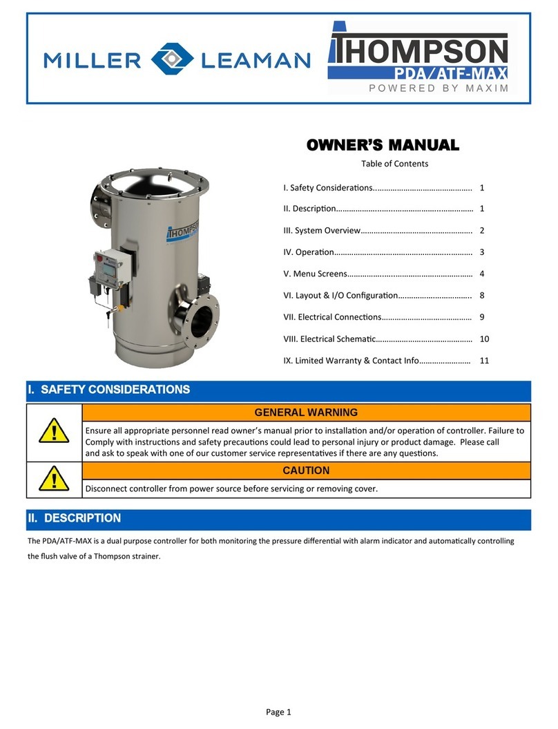
Miller-Leaman ATF Series User manual

OPEN/CLOSE
INDICATOR
COVER-PLATE SCREWS
(4) IN CORNERS OF BOX
(TIMER BASED VALVE
B
FROM PDA OR 120VAC PLUG
IN POWER SUPPLY
CONTROL SWITCH
A
GREEN POINTER
INNER RING
(LENGTH OF FLUSH)
(FACTORY SET AT
8-SECONDS)
RED POINTER
OUTER RING
(TIME BETWEEN
FLUSHES)
(FACTORY SET AT
24-HOURS)
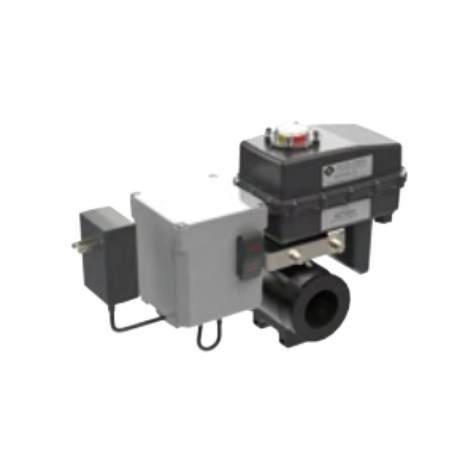
System Components: A. Timer Based Valve Controller (see illustration below)
sets the flush duration (length of the flush) and the flush interval (time between flushes)
B. Electric Ball Valve: designed for dirty water use. (see illustration below and next page)
Installation Instructions:
The following instructions are to be used as a guide when installing the ATF on to an existing Thompson Strainer, with an existing PDA Package. In the
case of Installing the ATF alone, omit steps 2 through 4, and then route the power supply cord through the plastic wire clamp and insert the low-voltage plug
coming from the wall power supply into the jack in the bottom of the ATF timer enclosure.
1. Carefully thread the electric operating valve onto the flush port of the strainer, with the control switch facing away from strainer (be careful not to
cross-thread when installing).
2. Route the coiled cord through the plastic wire clamp and insert the plug into the jack on the bottom of the timer enclosure.
3. Route the other end of the coiled cord through the wire clamp on the PDA enclosure and insert the plug into one of the jacks on the bottom of the PDA
enclosure.
4. Insert the low-voltage plug coming from the wall power supply into the other jack on the bottom of the PDA enclosure.
OPERATION INSTRUCTIONS: FLUSH VALVE MUST BE PLUMBED TO ATMOSPHERE. THE FLUSH LINE SHOULD NOT HAVE ANY ELEVATION
AND SHOULD NOT BE PIPED TO A PRESSURIZED LINE.
NOTE: THE AUTOMATIC TIMER FLUSH PACKAGE NEEDS TO BE PROGRAMMED WHEN IT IS RECEIVED BY THE END-USER. The programming
is simple and takes only a few moments. However, because every application has different parameters that affect the required frequency between flushes
and the duration of the flush, the end-user must choose the controller’s settings (please reference your strainer manual).
To program the ATF Controller:
Insert the 12-VDC plug coming from the Power Supply, or PDA unit, into the jack on the underside of the ATF box.
Plug the Power Supply into a 120-VAC outlet.
Please Note - In the case of an “Outdoor” use application, where there is a chance that the unit could get wet, it is the Customer’s responsibility
to provide a safe power outlet, in terms of being water proof, and physically able to accept the plug-in power supply we provide. Miller - Leaman,
Inc. also recommends that the installation be only preformed by a qualified electrician, and that all Local, State, and National Electrical Codes be
followed.
Test for power by momentarily pressing the manual flush side of the control switch (lower switch light should come on and the valve will start to open).
Adjust the ON TIME (Valve Open) by turning the inner timer ring with the GREEN POINTER clockwise to increase duration. The ON TIME RANGE is
factory set at eight seconds. (see illustration above)
Adjust the OFF TIME (Valve Close) by turning the outer ring with the RED POINTER clockwise to increase duration. The OFF TIME RANGE is factory
set at twenty-four hours. (see illustration above)
Set the control switch to auto flush. The red off light on the timer will come on and the upper light on the switch will come on and stay on. During the
flush cycle the on light on the timer and the lower switch light will come on.
Control Switch: (see illustration above)
Control switch flushing is initiated by pressing and holding down the manual control switch located on the front of the controller. The manual flush control
switch can also be used to conveniently drain the water out of the strainer before removing the conical screen element from the strainer housing. A yellow
indicator arrow on top of the ATF Valve will rotate in sync with the ball valve to show the valve position (open or closed). When the manual flush control
switch is released, the valve will automatically close.
Please Note - when the Control Switch is not in the AUTO position, the timer is disabled, and there will be no Timed Control of the Flush Valve -
Only Manual Flush when the Control Switch is pressed to MANUAL.
MILLER-LEAMAN, INC.
OPERATION INSTRUCTIONS
FOR THE THOMPSON STRAINER:
I. AUTOMATIC TIMER FLUSH PACKAGE
II. GENERAL INFORMATION
III. ATF WIRING SCHEMATIC
Description: The ATF valve package insures that the particulate that falls down to the debris reservoir is automatically flushed. The power control and timer
controls for the valve package are housed inside the ATF control box. Depending on the application, the end-user simply dials in the flush frequency and flush
duration of the valve (instructions below). Based on the parameters that are programmed, the ball valve quickly opens and closes, minimizing the volume of
water that is flushed from the strainer.
I. AUTOMATIC TIMER FLUSH PACKAGE
A
Fischer-Robertson, Inc.
3890 Symmes Road
Hamilton, OH45015
Ph 513-860-3445 Fx 513-860-4744
www.fischer-robertson.com

NOTICE: ATF PACKAGE REQUIRE A MINIMUM OF 10 PSI TO OPERATE
Valve Specifications
A. Water-resistant Polypropylene Actuator Motor Case
B. High Torque Motors with Permalube Gears
C. Open & Close Indicator
D. Ball Valve & Hardware
E. Auto Reset Circuit Breaker
F. 90 Degree Bi-directional Rotation
G. Controller Case
H. Easy Programmable Timer
Problem Possible Cause Solution
Valve is leaking past ball Seals damaged or worn out
Valve is not stopping at proper closed
position
Install repair kit
Adjust limit switches
Valve stem leaks Worn stem seals On metal valves: tighten stem packing nut 1/2 turn.
CAUTION! Over tightening stem nut could cause
drag on motor and trip internal circuit breaker. May
require repair kit or new valve.
Valve body leaks Loose body bolts or excessive operating
pressure.
Defective seals
Check bolts and observe recommended pressure
ratings
Install repair kits or new valve
Valve hard to turn Swollen seals or product buildup in valve
chamber
Valve bolts too tight
Stem nut too tight
Check valve for compatibility with product, may
require valve cleaning or new valve
Loosen bolts slightly
Loosen stem nut slightly.
TROUBLESHOOTING: If you require further assistance, please call us at (386) 248-0500.
AUTOMATIC TIMER FLUSH (ATF)
Water Resistance: The Valve and Controller are water-resistant, but not water-proof. Do not install below ground level where the component can be
submerged in water. Only remove the cover plate from the Valve Controller when setting or changing the flush settings. Keep the cover tightly sealed
on the unit during normal operation.
Miller-Leaman, Inc. Return Policy: New units or units less than 90-days old needing repair under warranty conditions must be returned to MLI and
must be accompanied by a Return Material Authorization (RMA) Number. To request a RMA Number call (386) 248-0500.
Please Follow Environmental Note: All ATF valves sent to MLI for repair must be cleaned and the valve rinsed and dried from all foreign residue or
the shipment will be returned “as is” to the customer. We cannot expose our technicians to the vast variety of chemicals used with the valve. Thank
you for your cooperation.
Maintenance: The ATF does not require regularly scheduled or annual maintenance. Valve leakage should be checked twice a year. If leakage is
visible consult your troubleshooting chart for possible solutions.
II. GENERAL INFORMATION
SAFETY FIRST! Keep fingers away from valve opening to avoid getting caught in the moving parts. The electric motor supplies a sufficient amount of
power to cause personal injury. Take precaution when handling.
Model Number
Flushport
NPT Size Valve Material
Maximum
Pressure
ATF-EA-.75 3/4" Nylon 300 PSI @ 70 deg. F
ATF-EA-1.0 1.0" Nylon 300 PSI @ 70 deg. F
ATF-EA-1.5 1.5" Nylon 200 PSI @ 70 deg. F
ATF-EA-2 2" Nylon 150 PSI @ 70 deg. F
ATF-EA-3 3" Poly 100 PSI @ 70 deg. F

MILLER-LEAMAN, INC.
800 ORANGE AVENUE - DAYTONA BEACH, FL 32114
(800) 881-0320 / (386) 248-0500 / (386) 248-3033
III. ATF WIRING SCHEMATIC
MADE IN THE USA
ML40034
(Rev. - 2/2/2016)
This manual suits for next models
5
Other Miller-Leaman Control Unit manuals
Popular Control Unit manuals by other brands
Eaton
Eaton PowerXL DE1 series manual
weed instrument
weed instrument EOTec 2000 installation instructions
DeZurik
DeZurik APCO CVS-250 instruction manual
ICP DAS USA
ICP DAS USA ZT-257 Series quick start guide

Gemalto
Gemalto Cinterion BGS2-W miniPCIe Hardware interface description
QTS
QTS P3 AN-X-TI-MAS user manual
