Behler-Young KSACN0601AAA User manual

Specifications subject to change without notice. OM-KSACN06(7)01-01
Owner’s Manual
Fig. 1 — Wired Controller
NOTE: Images are for illustration purposes only. Actual models may differ slightly.
Wired Remote Controller
7 Day Programmable Thermostat
Ductless Systems
KSACN0601AAA (High Wall/Console Models)
KSACN0701AAA Cassette/Ducted/Console / Air Handler Models)

2 Specifications subject to change without notice. OM-KSACN06(7)01-01
TABLE OF CONTENTS
PAGE
SAFETY CONSIDERATIONS...........................................................................................3
WIRED CONTROLLER FEATURES AND FUNCTIONS...............................................5
WIRED CONTROLLER DISPLAY ...................................................................................6
WIRED CONTROLLER FUNCTIONS .............................................................................7
INITIAL SETUP..................................................................................................................8
WEEKLY TIMER OPERATION .....................................................................................17
WEEK AND DAY SETTINGS FOR WEEK 2 ................................................................22
WIRED CONTROLLER ERROR CODES ......................................................................31
QUERIES AND SETTINGS .............................................................................................32
TECHNICAL INDICATION AND REQUIREMENT .....................................................38
NOTE: In order to properly service the wired controller, read this manual carefully prior to
operating the unit. Keep this manual after reading for future reference.

OM-KSACN06(7)01-01 Specifications subject to change without notice. 3
SAFETY CONSIDERATIONS
Installing, starting up, and servicing air-conditioning equipment can be hazardous due to system
pressures, electrical components, and equipment location (roofs, elevated structures, etc.). Only
trained, qualified installers and service mechanics should install, start-up, and service this equipment.
Untrained personnel can perform basic maintenance functions such as cleaning coils.
When working on the equipment, observe precautions in the literature and on tags, stickers, and labels
attached to the equipment.
Follow all safety codes. Wear safety glasses and work gloves. Keep a quenching cloth and fire
extinguisher nearby when brazing. Use care in handling, rigging, and setting bulky equipment.
Read these instructions thoroughly and follow all warnings or cautions included in the literature and
attached to the unit. Consult the local building codes and National Electrical Code (NEC) for special
requirements. Recognize safety information.
This is the safety-alert symbol . When you see this symbol on the unit and in instructions or
manuals, be alert to the potential for personal injury. Understand these signal words: DANGER,
WARNING, and CAUTION. These words are used with the safety-alert symbol.
DANGER identifies the most serious hazards which will result in severe personal injury or death.
WARNING signifies hazards which could result in personal injury or death. CAUTION is used to
identify unsafe practices which may result in minor personal injury or product and property damage.
NOTE is used to highlight suggestions which will result in enhanced installation, reliability, or
operation.

4 Specifications subject to change without notice. OM-KSACN06(7)01-01
ELECTRICAL SHOCK HAZARD
Failure to follow this warning could result in personal injury or death. Before beginning any modification or
installation of this kit, ensure the main electrical disconnect is in the OFF position. Ensure power is
disconnected to the fan coil unit. On some systems both the fan coil and the outdoor unit may be on the
same disconnect. Tag the disconnect switch with a suitable warning label. There may be more than one to
disconnect.
CAUTION
EQUIPMENT DAMAGE HAZARD
Failure to follow this caution may result in equipment damage or improper operation. Do not install the wired
controller in an area subjected to excessive steam, oil or sulfide gas. Doing so may damage the controller
and/or cause it to fail.
CAUTION

OM-KSACN06(7)01-01 Specifications subject to change without notice. 5
WIRED CONTROLLER FEATURES AND FUNCTIONS
Fig. 2 — Wired Controller
Features:
• Display
• Error code display
• Room temperature display
• Weekly Timer
Functions:
• Modes: Auto - Cool - Dry - Heat - Fan
• Fan speed: Auto/Low/Med/High speed
• Swing (on some models)
• Timer ON/OFF
• Temp setting
• Weekly timer
•FollowMe
• Child Lock
•Display
•Clock

6 Specifications subject to change without notice. OM-KSACN06(7)01-01
WIRED CONTROLLER DISPLAY
Fig. 3 — Wired Controller Display
1. Operation Mode
2. Fan Speed
3. Temperature Display
4. Lock
5. F/C
6. Main and secondary units (not available)
7. Turbo
8. Room temperature
9. Follow ME
10. Left-Right Swing
11. Clock Display
12. On/Off Timer
13. Timer Display
123457
8
9
10
11
1213
6

OM-KSACN06(7)01-01 Specifications subject to change without notice. 7
WIRED CONTROLLER FUNCTIONS
Fig. 4 — Wired Controller Functions
1. Power
2. Mode
3. Day Off/Del
4. Adjust
5. Confirm
6. Timer
7. Fan Speed
8. Back
9. Swing
10. Function
11. Copy
12. IR (Infrared) Signal Receiver
3
1
2
10
7
9
4
5
611
8
12

8 Specifications subject to change without notice. OM-KSACN06(7)01-01
INITIAL SETUP
Set the current day and time
NOTE: The Wired Controller can be powered
ON or OFF during this step.
1. Press TIMER for 2 seconds or more to set
the current date and time. The TIMER display
flashes (see Fig 5).
Fig. 5 —Timer
2. Press the UP or DOWN arrow (Fig. 6) to
set the week day; the selected week day
will flash (Fig. 7).
Fig. 6 —Up or Down Arrows
Fig. 7 — Days of the Week
3. Press TIMER to confirm. If there is no
button pressed within 10 seconds, the
displayed week day will be saved.
4. Press the UP or DOWN arrows (Fig. 6) to
set the current time. Press repeatedly to
adjust the current time in 1-minute
increments. Press and hold to adjust the
current time continuously. Press TIMER to
confirm. If there is no button pressed within
10 seconds the displayed time is saved.
Fig. 8 — Week Day and Time
5. Time scale selection: Press TIMER (See
Fig. 5 — on page 8) and DAY OFF (Fig. 9)
for 2 seconds to alternate the clock time
display between the 12 hour and 24 hour
formats.
Fig. 9 — Timer
ex. Monday 11:20

OM-KSACN06(7)01-01 Specifications subject to change without notice. 9
Start and Stop Operation
•PressPOWER (Fig. 10) to power on the
controller.
Fig. 10 — Power
To Set the Operation Mode
•PressMODE (see Fig. 11) to set the
OPERATION MODE (see Fig. 12) (HEAT
function is invalid for a COOL only type unit).
Fig. 11 — Mode
Fig. 12 — Operation Modes
Room Temperature Setting
1. Press the
UP
or
DOWN
arrow (Lower or Raise
(see Fig.13)) to set the room temperature.
NOTE: This function in unavailable in FAN mode.
Fig. 13 — Up or Down Arrows (Lower and
Raise)
Indoor Setting Temperature Range:
62°F~86°F (17°C~30°C)
2. °F and °C Scale Selection - Press and
hold the UP or DOWN arrow for 3 seconds
to alternate the temperature display
between the °F and °C scale.
Lower
Raise
10 Specifications subject to change without notice. OM-KSACN06(7)01-01
Fan Speed
•PressFAN SPEED to set the fan speed.
NOTE: This function is unavailable when the
unit is in AUTO or DRY mode.
Fig. 14 — Fan Speed
Keypad Tone
Enable Keypad Tone
•PressSWING and FUNC. together (Fig. 15)
for 3 seconds to enable the keypad tone.
Disable Keypad Tone
•PressSWING and FUNC. together (Fig. 15)
for 3 seconds to disable the keypad tone.
Fig. 15 — Keypad Tone Set
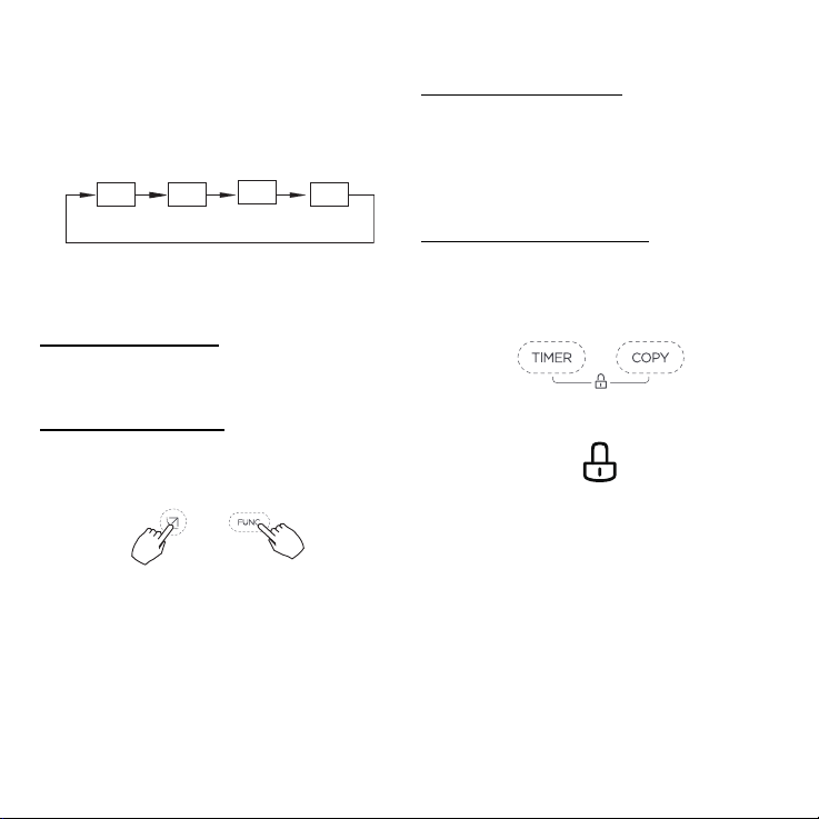
Use the Child Lock Function
Activate the Child Lock
•PressTIMER and COPY (Fig. 16) together
for 3 seconds to activate the CHILD LOCK
function and lock all the buttons on the wired
controller. When the CHILD LOCK function is
activated, the LOCK icon appears (Fig. 17).
De-activate the Child Lock
•PressTIMER and COPY (Fig. 16) together
for 3 seconds to deactivate the CHILD LOCK
function.
Fig. 16 — Timer and Copy
Fig. 17 — Child Lock
HIGHAUTO LOW MED

OM-KSACN06(7)01-01 Specifications subject to change without notice. 11
Use the Swing (UP-DOWN) Function
(for some models only)
1. Press SWING (Fig. 18) for 2 seconds to start
the UP-DOWN LOUVER SWING function.
When the function is activated, the UP -
DOWN SWING icon appears (Fig. 19).
NOTE: For the KSACN0601AAA model, press
SWING to start the UP-DOWN LOUVER
SWING function. For the KSACN0701AAA
model, press SWING for 2 seconds to start
the UP-DOWN LOUVER SWING function.
2. Press SWING again to stop.
Use the Swing (LEFT-RIGHT) Function
(for some models only)
1. Press SWING (Fig. 18) for 2 seconds to start
the LEFT-RIGHT SWING louver function.
2. Press SWING again for 2 seconds to stop.
When the
LEFT-RIGHT SWING
function is activated,
the
LEFT-RIGHT SWING
icon appears (Fig. 20).
Fig. 20 — Left-Right Swing
Turbo (on some models)
Under the COOL or HEAT mode, TURBO and
FOLLOW ME can be activated.
1. Press FUNC. to set the TURBO or FOLLOW
ME function. The select function icon flashes.
Fig. 21 — FUNC.
2. Press CONFIRM to confirm the setting
(see Fig. 22).
Fig. 22 — Confirm the Setting
When TURBO is activated, the TURBO
icon appears (see Fig. 23).
Fig. 23 — Turbo
Fig. 18 — Swing
Fig. 19 — Up-Down Swing

12 Specifications subject to change without notice. OM-KSACN06(7)01-01
FOLLOW ME
Activate FOLLOW ME
1. Press
FUNC.
to select the
FOLLOW ME
icon.
2. Press CONFIRM to activate FOLLOW ME.
Deactivate FOLLOW ME
1. Press
FUNC.
to select the
FOLLOW ME
icon.
2. Press CONFIRM to deactivate.
Fig. 24 — FOLLOW Me
Indoor Unit
When the FOLLOW ME function
indication appears, the room
temperature is detected by the sensor
in the wired controller.
OM-KSACN06(7)01-01 Specifications subject to change without notice. 13
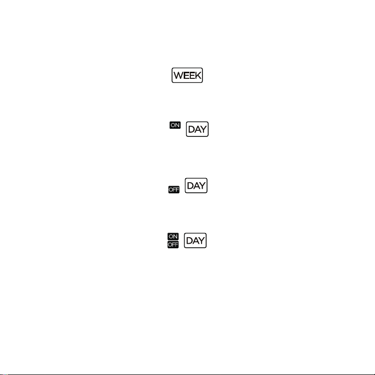
Timer Functions
For more information, see “To Set the ON or OFF TIMER” on page 14.
•Weekly: Use the WEEKLY function to set operating times for each day of the week.
Fig. 25 — WEEK
•On:Day: Use the ON:DAY function to start air conditioner operation.
Fig. 26 — ON:DAY
• Off:Day: Use the OFF:DAY function to stop air conditioner operation.
Fig. 27 — OFF:DAY
• On and Off:Day: Use the On and Off: Day function to start and stop air conditioner operation.
Fig. 28 — ON and OFF:DAY

14 Specifications subject to change without notice. OM-KSACN06(7)01-01
To Set the ON or OFF TIMER
1. Press TIMER to select the ON:DAY or OFF:DAY.
Fig. 29 — Select the ON:DAY or OFF:DAY
2. Press CONFIRM and the TIMER display flashes.
Fig. 30 — Confirm
3. Press the UP or DOWN arrow to set the time. After the time is set, the timer starts or stops.
Fig. 31 — Up or Down arrow to set time
4. Press CONFIRM.
Fig. 32 — Confirm
No display
ex. O timer set at 18:00

OM-KSACN06(7)01-01 Specifications subject to change without notice. 15
Week and Day Settings for WEEK 1
WEEK 1 Timer Setting
1. Press TIMER (several times if needed) to select WEEK 1.
2. Press CONFIRM.
Fig. 33 — Press Timer then Confirm
Day of the WEEK Setting
1. Press the UP or DOWN arrow to select the day of the week.
2. Press CONFIRM.
Fig. 34 — Press Up and Down Arrows - Select Day - Confirm

16 Specifications subject to change without notice. OM-KSACN06(7)01-01
SET the ON Timer for Timer Setting 1
1. Press the UP or DOWN arrow to set the time of the ON timer.
2. Press CONFIRM.
Fig. 35 — Up or Down Arrow - Confirm
Fig. 36 — Select Timer Setting(s)
Set the OFF Timer Setting for Timer Setting 1
1. Press the UP or DOWN arrow to set the OFF timer.
2. Press CONFIRM.
Fig. 37 — UP or DOWN Arrow - Confirm
NOTE: Users can revert to the previous step by pressing BACK. The time of the timer setting can be
deleted by pressing DAY OFF. The current setting is restored and the weekly timer setting is withdrawn
when there is no operation selected in 30 seconds.
ex.Tuesday time scale 1
Up to 4 timer settings can be saved for each day of the week.
ex. Tuesday time scale 1

OM-KSACN06(7)01-01 Specifications subject to change without notice. 17
WEEKLY TIMER OPERATION
To activate the WEEKLY TIMER operation
1. Press and release TIMER until WEEK 1 appears on the display.
Fig. 38 — Press Timer
To deactivate the WEEKLY TIMER operation
1. Press and release TIMER until WEEK 1 no longer appears on the display.
Fig. 39 — Press Timer
ex.
ex.

18 Specifications subject to change without notice. OM-KSACN06(7)01-01
To Turn Off the Air Conditioner with the Week Timer
1. Press POWER and the air conditioner turns OFF temporarily. The air conditioner turns back on
automatically when the ON timer’s set time is reached. For example, press POWER once at 10:00
AM, the air conditioner turns back on at the timer setting 2:00 PM (Fig. 40).
Fig. 40 —Weekly Timer Display
2. Press POWER for 2 seconds, the air conditioner turns off completely and cancels the timing
function.
ON OFF ON OFF
8:00AM 12:00PM 2:00PM 5:00P
M
10:00AM

OM-KSACN06(7)01-01 Specifications subject to change without notice. 19
Set the DAY OFF For WEEK 1
1. Select WEEK 1 then press CONFIRM. For more information, see “WEEKLY TIMER
OPERATION” on page 17.
Fig. 41 — Confirm
2. Press the UP or DOWN arrow to select the day of the week.
Fig. 42 — Up or Down Arrows
3. Press DAY OFF to select day(s) off.
Fig. 43 — Select Day(s) off
A DAY OFF can be set for other days by repeating steps 2 through 3.
4. Press BACK to revert to the weekly timer.
Fig. 44 — Back
The DAY OFF setting is canceled at the end of the set day.
ex. The DAY OFF is set for Wednesday
The mark is hidden

20 Specifications subject to change without notice. OM-KSACN06(7)01-01
Copy the Setting from One Day to Another
A scheduled event, made once, can be copied to another day of the week. The scheduled events of the
selected day will also be copied to the new day.
1. During the weekly timer, press CONFIRM.
Fig. 45 — Confirm
2. Press the UP or DOWN arrow to select the day to copy from.
Fig. 46 — Up or Down Arrows
3. Press COPY, “CY” appears on the display.
Fig. 47 — Copy
4. Press the UP or DOWN arrow to select the day to copy to.
Fig. 48 — Up or Down Arrow
This manual suits for next models
3
Table of contents


