BEHLMAN INV 2500 Use and care manual

0
USER'S GUIDE AND
TECHNICAL REFERENCE
DC TO AC INVERTER
BEHLMAN MODEL INV 2500
FOR SERVICE ASSISTANCE
CONTACT BEHLMAN
CUSTOMER SERVICE DEPARTMENT
PHONE TOLL FREE 1-800-874-6727
OR WRITE
BEHLMAN
CUSTOMER SERVICE DEPARTMENT
80 CABOT COURT
HAUPPAUGE, NY 11788
PHONE: (631) 435-0435
FAX : (631) 951-4341
FOR SALES INFORMATION:
PHONE: (631) 435-0435
USA : (800) 874-6727
FAX : (631) 951-4341
DATE:01/13 REV. 1

1
SAFETY SUMMARY
The following safety precautions must be observed during all phases of operation,
service, and operation of this equipment. Failure to comply with these precautions
or with specific warnings elsewhere in the manual violates safety standards
associated with the design and intended use of this equipment.
GROUND THE EQUIPMENT
To minimize shock hazard, the equipment chassis(s) must be connected to an electrical
safety ground (protective earth). This equipment is supplied with a three conductor line
connection for single phase applications and a five wire connection for three phase
applications. Both types include an earth terminal intended for safety ground
connections. Failure to use the protective earth connection may expose operating
personnel to hazardous voltages. In addition this earth connection provides a return path
for the equipment EMI filter(s).
DO NOT OPERATE IN EXPLOSIVE ATMOSPHERE
Do not operate the equipment in the presence of flammable gases or fumes. Operation
of any electrical instrument in such an environment constitutes a definite safety hazard.
KEEP AWAY FROM LIVE CIRCUITS
Operating personnel must not remove equipment covers. Component replacement and
internal adjustments must be made by qualified maintenance personnel. Do not replace
components with power applied. Under certain conditions, dangerous voltage may exist
even with the power removed. To avoid injuries, always disconnect power and discharge
circuits before touching them.
DO NOT SERVICE OR ADJUST ALONE
Do not attempt internal service or adjustment unless another person, capable of
rendering first aid and resuscitation is present .
DO NOT SUBSTITUTE PARTS OR MODIFY EQUIPMENT
Because of the danger of introducing additional hazards, do not install substitute parts or
perform any unauthorized modification to this equipment. Contact Behlman Electronics
for proper replacement parts and specific service information.
!DANGEROUS PROCEDURE WARNINGS
Warnings will precede potentially dangerous procedures in this manual. Instructions
contained in the warning must be followed.

2
CLAIM FOR DAMAGE IN SHIPMENT
Under the FOB factory terms of sale, ownership and responsibility are transferred to the customer when the
equipment leaves the factory. Each Behlman equipment is shipped from the factory in proper operating
condition.
Immediately upon receiving equipment, unpack and inspect it for evidence of damage incurred in shipment.
File a claim with the freight carrier if the equipment has been damaged in any way or it fails to operate
properly. Forward a copy of the damage claim report to Behlman. Include the model number, serial number
and date the shipment was received. Behlman will advise the disposition of the equipment and will arrange
for necessary repair or replacement.
RETURNING EQUIPMENT TO FACTORY
Do not return equipment to the factory without prior authorization from Behlman.
A RETURN MATERIAL AUTHORIZATION NUMBER (RMA) is required to return equipment.
This equipment, like all precision electronic equipment, is susceptible to shipping damage. It contains
heavy magnetic components as well as delicate electronic components.
If equipment is returned without prior authorization, the shipment will be refused, the customer being liable
for all shipping, handling and repair costs.
When packing for reshipment, use the original shock absorbent material and shipping container to preclude
damage to the equipment.
Insure that the return authorization numbers (RMA) is available on the container for identification.
SHIPPING INSTRUCTIONS
RACK MOUNTED UNITS
1) Box (es) must be double wall with minimum 350 lbs. bursting test.
2) Box (es) must provide for a minimum of 3to 4 inches of clearance around sides, top and bottom of
unit.
3) When packing unit, utilize either a foam-in-place system or high density foam. Clearance provided
for above must be completely filled with foam.
FAILURE TO COMPLETELY SECURE UNIT IN BOX WILL ALLOW
MOVEMENT DURING SHIPPING, RESULTING IN DAMAGE.
4) Secure box (es) to pallet (s). This is necessary to insure proper handling and protection during
shipping.
5) Place the following warning label on box (es)
DO NOT STACK
6) Ship unit (s) using a freight cargo carrier; air or ground.
CABINET MOUNTED UNITS
Cabinet mounted units require that a special crate be used. The crate should be manufactured of plywood
(3/8" or thicker) and reinforced (using 1 x 3 or larger pine) on all edges. The unit must be firmly secured to
the crate’s base. The crate must be shock mounted to avoid damage during shipping. Detail drawings for
Behlman's crates are available upon request.

3
WARRANTY CERTIFICATE
Behlman Electronics, Inc. warrants to the original purchaser, for a period of one (1) year from the
shipment from Behlman, each item to be free from defects in material and workmanship. Behlman’s
obligation and the Purchaser’s sole remedy for any breach or violation of this agreement is limited to
adjustments, repair or replacements for parts which have been promptly reported by the Purchaser as
having been in its opinion, defective and so found by Behlman upon inspection. All replacement parts will
become the property of Behlman on an exchange basis. This warranty will not apply if such adjustment
repair or parts replacement is required because accident, neglect, misuse, failure of environmental controls,
transportation damage or causes other than normal use.
If during the warranty period a defect should impair the performance of the unit, Behlman agrees, at its
option, to repair or replace the unit or its defective components F.O.B. Behlman at 80 Cabot Court,
Hauppauge NY 11788 or at another Behlman service facility at Behlman’s option. To obtain service under
this warranty, the original Purchase shall notify Behlman at the above address or by telephone at 631-435-
0410 and provide information about the defect or impairment of performance. Behlman with then supply
the Purchaser a Return Material Authorization (RMA) number. This number must be attached to the
equipment sent back for warranty repair. Equipment must be shipped back to Behlman prepaid. No collect
shipments will be accepted.
Behlman shall be excused from supplying warranty service if the unit’s case has been open or if the unit
has been subject to unauthorized repair. All service outside the scope of this warranty shall be paid for by
the Purchaser at Behlman’s rates in effect at the time of this repair. Behlman will not perform any repairs
outside of the warranty without written authorization by the Purchaser. If the repair is a warranty repair,
Behlman will ship the unit back to the Purchaser, by a method determined solely by Behlman, prepaid. If
the Purchaser requests, any other means of transportation it shall be at the Purchaser’s expense.
The use of the equipment shall be under the Purchaser’s exclusive management and control. The Purchaser
will be responsible for assuring the proper installation, use, management and supervision of the equipment.
Behlman will not be liable for personal injury or property damage.
The forgoing warranties are in lieu of all other warranties, expressed or implied including without
limitation warranties of merchantability and fitness for purpose.
In no event shall Behlman be liable for loss of profits, loss of use, or any indirect, consequential or
incidental damages. Purchaser agrees that Behlman will not be liable for any damages caused by the
Purchaser’s failure to fulfill any of the Purchaser’s responsibilities set forth herein.

4
TECHNICAL REFERENCE
MODEL SERIES INV2500 DC TO AC INVERTERS
TABLE OF CONTENTS
1.0 INTRODUCTION
1.1 Specifications
2.0 INSTALLATION
2.1 General
2.2 Wiring
2.3 Optional Alarm Contacts
2.4 Optional Step-up Transformer
3.0 OPERATING INSTRUCTIONS
3.1 Controls and Indicators
3.2 Optional alarm contacts
3.3 Operational Considerations:
Load Limitations
Powering Reactive Loads
Powering Lamps
Powering Motors
Powering Non-Linear Loads
4.0 TROUBLESHOOTING
4.1 Theory of Operation
4.2 Trouble Shooting
4.3 Maintenance
5.0 MECHANICAL OUTLINE

5
INV 2500 SERIES MANUAL REV 1 1/13
SECTION 1
GENERAL INFORMATION
1.0 INTRODUCTION
The Behlman INV 2500 series of DC to AC power inverters incorporate the latest in
switched mode power technology to provide regulated AC power from a user
supplied DC source. These devices produce a sinewave output comparable to that
which is available from typical utility power. Each model provides electronic
protection along with a high short term overload capacity making them ideal for many
loads requiring large “in - rush” currents. All units are housed in a rugged steel
enclosure making them well suited to operation in industrial applications.
Available options include an AC input bypass and signaling contacts. The AC
bypass option is available in two configurations. The “DI” option favors the DC input
and will switch to AC when the DC input is lost. The second option , A1, will favor the
AC line input and will switch to the inverter if the line is lost. These features allow the
unit to be incorporated into a user defined back-up power system.
1.1 SPECIFICATIONS
INPUTS:
MODEL DC INPUT DC BURDEN (full load) DC BURDEN ( no load)
2500 - 125 125 DC +/- 20 % 31 AMPS @ 100 VDC 550 mA +/- 20%
2500 - 48 48 VDC +/- 20 % 80 AMPS DC @ 38 VDC 1.7 A +/- 20%
AC INPUT (optional bypass mode only) 130 Vac max @ 15 amps ( internal fuse )
OUTPUT
Power: 2500 VA
Voltage: 120 VAC +/-2% 60 Hertz ( available @ 50 and 400 Hertz)
220-240V output available with external transformer option.
Current: 21 amps RMS continuous ( 30 amps peaks )
Waveform: Sine wave with less than 3% T.H.D. ( linear load)
efficiency: Better than 85% at nominal input.
PROTECTION
Input: DC circuit breakers (optional AC input has 15 amp fuse)
Output: Electronic over current protected.
Thermal: Thermal cut-out monitors temperature. Shuts down during
Over-temp conditions. Automatic Reset.
MECHANICAL
10.45"H x 19" W x 19"D ( rack mountable)
ENVIRONMENTAL
Operating temperature 0 to +55C , 95% RH non - condensing

6
INV 2500 SERIES MANUAL REV 1 1/13
SECTION 2
INSTALLATION
2.1 INSTALLATION
! WARNING
INSTALLATION AND OPERATION OF THIS DEVICE MAY EXPOSE HAZARDOUS
VOLTAGES. REFER TO QUALIFIED PERSONNEL ONLY.
The INV 2500 series inverters are designed to be installed in a standard 19" relay
rack or EIA type enclosure. The front panel has a set of “ears” provided for this
purpose. The mounting holes are designed to conform to EIA rack standards.
Mount the unit in a suitable location as not to block the flow of cooling air at the front,
rear, and sides of the inverter chassis. This device will pull in cool air from the front
and sides and exhaust warm air from the rear. It is recommended that a minimum
clearance of 3 inches be provided at the front and rear and 1 to 2 inches on the
sides. Enclosures must be vented.
When rack mounting,
DO NOT
mount the inverter by the mounting ears only. If
the unit is intended for use in a mobile or other high vibration application the use
of additional support for the rear of the chassis is mandatory.
2.2 WIRING
Wiring to the inverter will vary depending on input voltage and any options ordered.
In addition local electrical codes must be considered for permanent installations. The
NEC (National Electrical Code) requires that separately derived AC sources such as
back-up generators, inverters, etc., must have one output conductor tied to a
protective earth. This may be accomplished with the 2500 series by following the
recommended hook up diagrams provided here.
! WARNING
ALL INSTALLATIONS AND VERSIONS OF THIS DEVICE REQUIRE THE USE OF
THE SAFETY EARTH CONNECTION TO THE CHASSIS. FAILURE TO DO SO MAY
CREATE A SHOCK HAZARD. THE VOLTAGE AND CURRENT PRODUCED BY THIS
UNIT CAN BE LETHAL.
7
INV 2500 SERIES MANUAL REV 1 1/13
SECTION 2
INSTALLATION
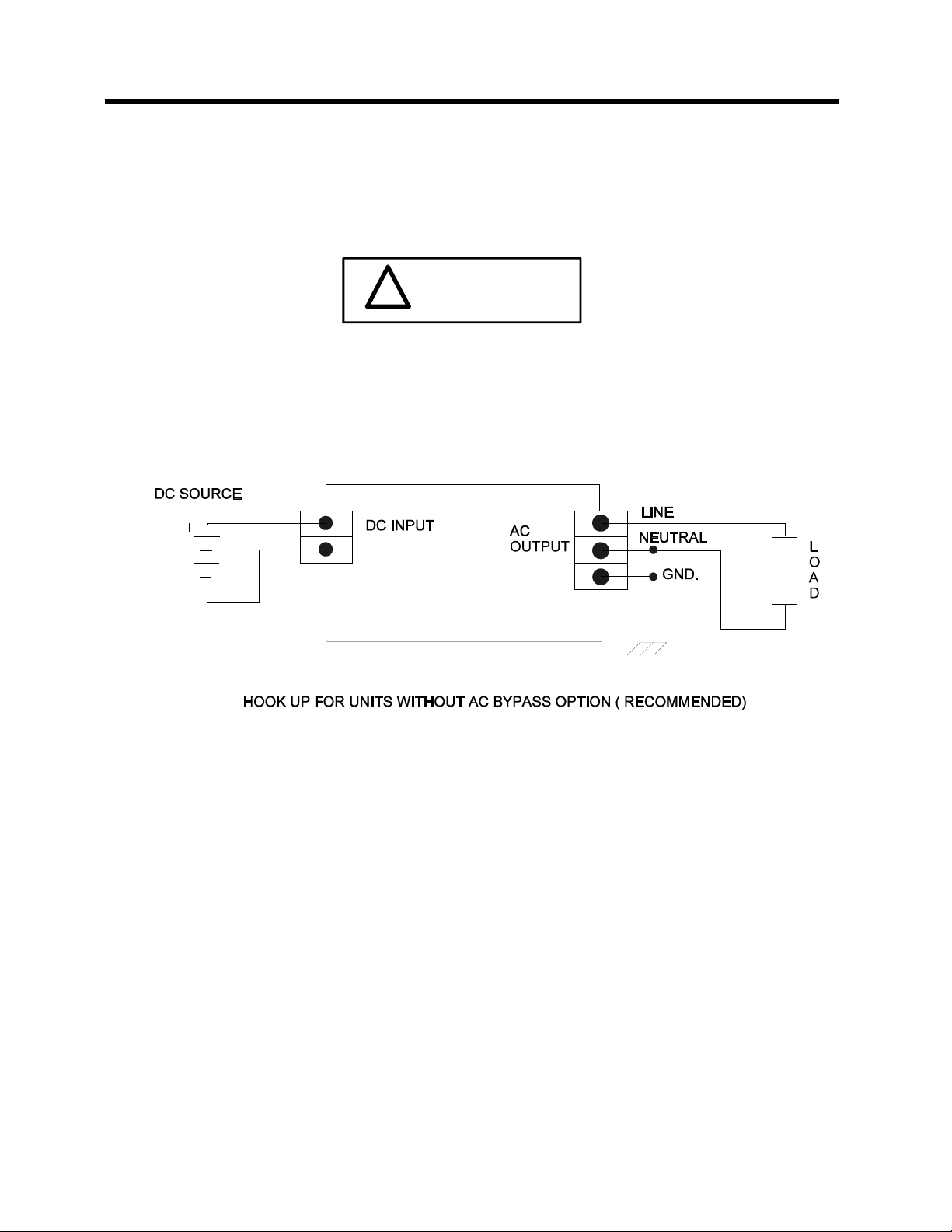
2.2 WIRING ( continued )
Figure 2-1 illustrates the wiring for models that do not include any options. The units
have two a screw type terminal block located on the rear panel. Compatible loads
may be connected into this terminal block. See section three of this manual for more
information.
!CAUTION
!
FAILURE TO OBSERVE DC POLARITY ON THE INPUT TO THIS DEVICE MAY
CAUSE DAMAGE TO INTERNAL CIRCUITRY. THIS WILL VOID EQUIPMENT
WARRANTY
FIGURE 2-1

8
INV 2500 SERIES MANUAL REV 1 1/13
SECTION 2
INSTALLATION
2.2 WIRING ( continued )
Units supplied with the AC input bypass option will wired slightly differently. To
conform to NEC 250 the neutral is “carried through” to the output but is not shorted
to the GND terminal. This will place one side of the inverter output at the neutral
potential. It should be noted that this is only recommended to satisfy the NEC
requirements. The output of the inverter is isolated from the DC input and the line.
This allows the output to be floating if required by end user’s application. Maximum
continuous common mode potential is limited to 250Vac or 360Vdc. Figure 2-2
illustrates a typical bypass configuration.
.
Figure 2-2
The recommended wire size for each model is listed below in table 2-1. These sizes
are based on a maximum wire length of 10 to 15 feet. Longer wires should be
increased in diameter.
MODEL # DC INPUT WIRING AC INPUT \ OUTPUT WIRING
2500-48-XX # 6 AWG ( 60 A) # 10 AWG ( 25 A max.)
2500-125-XX # 10 AWG (23 A typ.) # 10 AWG ( 25 A max )
Table 2-1
9
INV 2500 SERIES MANUAL REV 1 1/13
SECTION 2
INSTALLATION
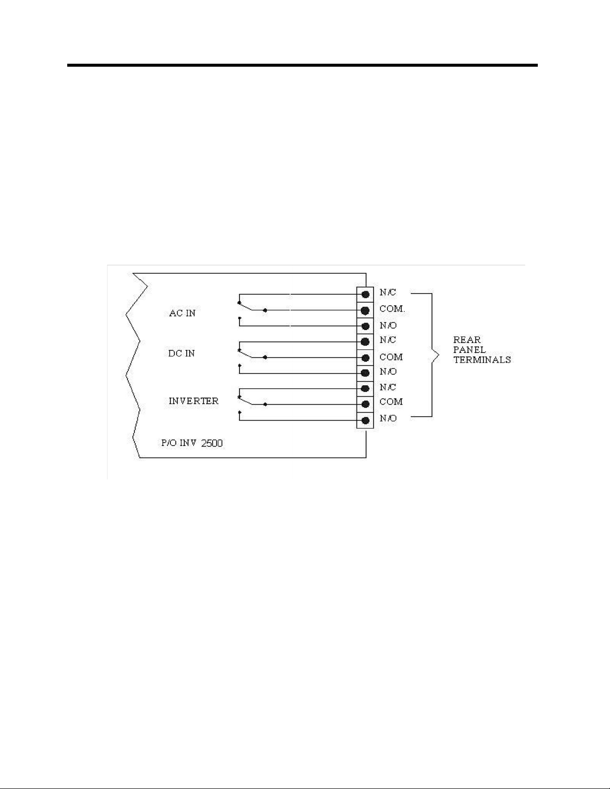
2.3 OPTIONAL ALARM CONTACTS
Units supplied with the bypass option also provide signal contacts that can be used
to set alarms or trigger other system related responses to operating conditions.
The alarm contact option provides the user with a convenient means of monitoring
of the status of : DC input, AC input, and INVERTER (inverter AC output). Each
function provides one set of “dry” C form contacts which accommodate any logic
required. The internal relays will change state if any of the three voltages are missing
or too low to provide proper operation. The contact rating of the alarm functions are
0.3 amp @ 125 Vac maximum. The figure 2-3 below illustrates the alarm internal
wiring.
Figure 2-3
To prevent possible EMI ( electro-magnetic interference ) alarm wiring should be
accomplished with twisted pairs. Shielding is also recommended. This will prevent
interference from entering or leaving the unit. All alarm connections should be made
with #6 inside diameter ring lugs. A rear panel terminal block is provided. See section
three of this manual for further information.
2.4 OPTIONAL STEP-UP TRANSFORMER
The INV series can provide a 220V or 240V output with the addition of an external
transformer chassis . With this option a second rack mountable chassis is provided
to convert the standard 120V output to the higher value. In addition, the bypass
option can also be included with the external transformer.

10
INV 2500 SERIES MANUAL REV 1 1/13
SECTION 2
INSTALLATION
2.4 OPTIONAL STEP-UP TRANSFORMER ( continued )
A block diagram of the optional transformer configurations is provided in figure
2-4. Special units may vary and will be identified by a four digit engineering code.
Interconnecting wiring should be rated at 250Vac or better. Ring lugs are
recommended for all connections.
Figure 2-4 External Step-up transformer block diagrams

11
INV 2500 SERIES MANUAL REV 1 1/13
SECTION 3
OPERATION
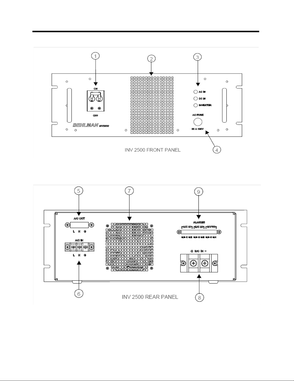
3.1 CONTROLS AND INDICATORS
Table 3-1 below lists and describes the various control, indicator, and connectors
associated with this model. Figures 3-1 & 3-2 illustrate the location of items listed
in table 3-1.
ITEM DESIGNATION FUNCTION
1 POWER Front panel mounted magnetic circuit breaker,
also serves as DC on/off switch.
2 AIR INTAKE Pulls in air for cooling internal power components.
3 STATUS LEDS Provided with alarm by/pass option. Used to
indicate status of alarm circuits. Green LEDs
indicate a O.K. condition for :
AC input, DC input, and inverter output.
4 LINE BYPASS FUSE Provided with alarm /bypass option. Used to
protect AC wiring due to load fault. Fuse rating is
30A @ 120V.
5 OUTPUT CONNECTOR Standard units provide screw type terminal blocks.
6 AC LINE INPUT TERMINALS Screw type terminal block provided with
alarm/bypass option. For connection to bypass
source.
7 FAN EXHAUST Heated air exhaust. Minimum 4 inch clearance
required for full power operation.
8 DC INPUT Screw type terminal block to connect DC input.
9 ALARM SIGNAL TERMINAL Screw type terminal block to connect alarm
signals.
The table above lists the most common configurations for this model series. It should be
noted that Behlman has produced many modified or semi-custom version of this model. This
will be indicated by a four digit engineering code number appearing at the end of the model
number. For this reason this table may not contain all the information for special units.
Addendums will be placed at the beginning of this manual to address any important
variations and/or operating considerations.
When requesting information for this series any four digit engineering code should be
provided
.
12
INV 2500 SERIES MANUAL REV 1 1/13
SECTION 3
OPERATION
3.1 CONTROLS AND INDICATORS
FIGURE 3-1
FIGURE 3-2

13
INV 2500 SERIES MANUAL REV 1 1/13
SECTION 3
OPERATION
3.2 OPERATION
1 Connect the load to the inverter. If multiple loads are used it is good practice to switch all loads
off before switching on the inverter. This will prevent multiple in - rush currents from tripping
protective circuits in the inverter.
2. Switch on the inverter. At this point, the sound of the cooling fans should be evident.
3. If the inverter contains the alarm \ bypass option, the appropriate front panel LEDs
should be illuminated.
4. To test the inverter, use a True RMS type meter to confirm the output voltage is as
specified.
5. Units provided with the AI bypass option are AC preferred. This means that the incoming AC
line voltage will be routed to the inverter output terminals ( or outlets ) when ever it is present.
During this time the inverter is in a standby condition. If the AC input is removed the output
terminals will be switched to the inverter and operation from the DC source begins.
The AI bypass function can be verified by removing the AC line input. This will cause the AC
IN LED to turn off and the AC IN alarm contacts to change state. During this time the
INVERTER and DC IN LEDs should remain on. Confirm an AC output from the output
terminal or outlet.
Units provided with the DI bypass option are DC preferred. This means that the inverter is
routed to the output terminals ( or outlets ) whenever DC is available. If the DC is lost or the
inverter malfunctions, the incoming AC line will be routed to the output terminals.
The DI bypass function can be verified by removing the DC input (leave front panel breaker
on ). Confirm that the DC IN and INVERTER LEDs turn off and the corresponding rear panel
alarm contacts change state. The AC IN LED will remain on and the AC IN contacts do not
change state . Use a voltmeter to confirm that the input AC is routed to the unit’s output
terminals or outlets.
3.3 OPERATIONAL CONSIDERATIONS
LOADING LIMITATIONS:
The INV series are designed to produce a power level of 2500 Watts( real power) under continuous
operating conditions. In addition, they can supply bursts of over 1500 watts for several seconds. Peak
repetitive currents on the order of 50 amps may also be supplied continuously as long as they do not
exceed the RMS value of 25 amps.
This high peak current capability allows the INV 2500 series to start most high in - rush loads in it’s
power range. It must be understood that the DC power source suppling the inverter must also have
this capability in order to derive these benefits. A poorly regulated or high internal resistance DC power
source will adversely affect operation of the inverter.
POWERING REACTIVE LOADS
Capacitors and inductors are reactive in nature. With capacitors, if the load is applied during the peak
of the AC cycle there may be a considerable in rush of current several magnitudes larger than the
steady state current. This current is only limited by any series resistance that may be present in the
load circuit. Under the right conditions, this could trip the overload protection circuits in the inverter.
Certain transformers and solenoids (inductance) present the same problem due to magnetizing
currents.

14
INV 2500 SERIES MANUAL REV 1 1/13
SECTION 3
OPERATION
3.3 OPERATIONAL CONSIDERATIONS
POWERING REACTIVE LOADS
( continued )
Several methods can be used to prevent tripping the protection circuits in the power source . One
common method is to insert a limiting impedance in series with the load. This could be in the form of
a fixed resistor or NTC (negative temperature coefficient) thermistor. Also, zero crossing switching can
be employed. Most commercial DC power supplies present a capacitive in-rush characteristic. Line
filters with large shunt capacitance may also cause considerable in rush current “spikes”. If not
accounted for these loads can trip protective circuits in the inverter.
POWERING LAMPS
Tungsten filaments lamps, when cold, present a very low resistance. Once they are energized, their
resistance quickly climbs to it’s steady state value. This characteristic must be accounted for when
driving tungsten filament lamps. Like incandescent lamps, certain Ni-Chrome based heaters will
present a 2:1 or 3:1 in rush when cold. The same methods for limiting in rush current for reactive loads
can be applied to tungsten or Ni-Chrome base elements.
POWERING MOTORS
Driving an AC motor presents a special problem. Most motors require a starting current that can be
several times higher than the running current. This current may last for a few cycles to several seconds
depending on the construction and mechanical load on the motor. This current is sometimes referred
to as the motor’s “locked rotor” current. This current is not to be confused with the in- rush current that
usually occurs over the course of one or two cycles of the AC waveform.
The model 2500's fold back current limiting can be an advantage when starting motors. During the
starting period the motor will attempt to draw excessive power from the inverter. The fold back circuit
will reduce the output voltage in order to maintain the maximum output current. During this time the
current supplied to the motor will remain sinusoidal, this allows the motor to start rotating. Once the
motor reaches it’s normal operating speed, it generates the required “back EMF” to reduce the supply
current to the nominal “run” value for the motor.
POWERING NON-LINEAR LOADS
Loads utilizing rectifiers and SCRs interact with the AC power source and have a significant effect
on the distortion of the output waveform. Consider the use of a bridge rectifier followed by a capacitive
filter, the current waveform associated with this circuit is illustrated below in figure 3-3. The input
current to this type of circuit is drawn in large “gulps” whenever the voltage across the capacitor falls
below the peak of the input waveform. The capacitor charging current is limited only by the series
impedance present in the wiring and capacitor .Because the impedance of large electrolytic capacitors
is very small this action causes a current wave form with a peak value several times the RMS value.
This ratio of peak current to RMS current is known as “ Crest Factor”. High values of crest factor cause
distortion of the AC voltage waveform.
The amount of distortion incurred is dependant on many factors and is beyond the scope of this
manual. It should be noted that this type of load may cause the output waveform to exhibit “flat topping”
This should not be associated with a defect of the inverter. Most “real world” electric distribution
systems exhibit this distortion for this reason.

15
INV 2500 SERIES MANUAL REV 1 1/13
SECTION 3
OPERATION
3.3 OPERATING CONSIDERATIONS
Figure 3-3 below give an example of a non-linear load. In this case the load current is said to be
discontinuous as it does not flow over the full cycle of the output waveforms. This action can cause
perturbations on the output waveform. This may show up as ringing or clipping. Ringing can be
reduced by adding a small resistive “ pre-load” of about 10 to 20 watts across the output terminals.
FIGURE 3-3

16
INV 2500 SERIES MANUAL REV 1 1/13
SECTION 4
TROUBLE SHOOTING
4.1
THEORY OF OPERATION
The INV 2500 series utilizes high frequency, switched mode, power conversion to convert
the incoming DC to an AC output. The first stage is a DC to DC converter which “steps - up”
the input voltage to a regulated +/- 200 Vdc. This voltage is applied to a second high
frequency “housekeeping” supply and the output inverter. The housekeeping supply provides
operating voltages for the output inverter and alarm circuits. The output section consists of
a crystal controlled sine wave oscillator and class “D” power amplifier. The crystal derived
clock frequency is divided down and applied to a counter, PROM, D/A converter
combination. The resulting sine wave at the output frequency is applied to the power
amplifier and boosted to the 120 VAC level required on the output.
The power amplifier consists of a pulse width modulated ( PWM ) “half bridge” circuit utilizing
IGBT output devices. The devices are switched at a rate of 20 KHZ and modulated with the
sine wave information. The result is a 400V p/p pulse train at the output that contains the
original sine wave information. The 20 KHz “carrier” frequency is removed by a low pass LC
filter . This provides an amplified version of the original modulation signal to the output
terminals. The control circuitry on the output inverter assembly also provides output
regulation and protective functions. The output voltage RMS value is monitored and used to
keep the output regulated. Output current is measured and used to provide fold back type
limiting in the event of an overload. Output short circuits will disable the inverter stage,
requiring the input power to be recycled to return proper operation.
The alarm and bypass circuits ( if provided ) allow for external monitoring of input and output
status. The AC input/ bypass feature allows the AC power line to be applied to the model INV
2500 and sent directly to the output terminals. In the event the AC is interrupted, a relay will
switch the output to the inverter. Units supplied with the D1 option will switch the line through
when the DC is not available or the inverter has a fault. The AC input is fused at 30 amps.
Figure 4-1 INV 2500 Block Diagram ( with By-pass option)

17
INV 2500 SERIES MANUAL REV 1 1/13
SECTION 4
TROUBLE SHOOTING
4.2 TROUBLESHOOTING
In the event problems are encountered during the installation and operation of the inverter refer to the
chart below before assuming the inverter is at fault. If It is determined the fault is with the inverter,
contact Behlman Electronics for service information.
SYMPTOM POSSIBLE CAUSE ACTION
Low or no output Output overloaded Check load current . Disconnect
load and recheck
output voltage using TRMS
meter. Recycle power.
Erratic operation Input voltage fluctuating Monitor voltage at DC input
terminals of inverter. Make
sure it is with in specifications
No AC input alarm
( optional)
AC - Bypass fuse blown Check fuse. Measure AC input
at rear panel.
Output distorted High peak load current Reduce loading if distortion
is objectionable.
DC breaker repeatedly trips DC polarity reversed or internal
fault in inverter.
Check polarity, if ok, the unit
may have an internal fault.
Return for service
! WARNING
Service of this device requires specialized equipment and trained personnel. There are no internal
user serviceable parts. Removing the cover will expose individuals to hazardous voltages.
Refer
service to qualified persons only !
4.3 MAINTENANCE
The INV 2500 series requires very little in the way of routine maintenance. If the unit is operated in a
dirty or dusty environment it should be removed from service periodically and cleaned. The use of
forced air is perfect for cleaning dust and debris from fan intakes and heat sink assemblies. Light
brushing and vacuuming is also effective.
If the unit is to be supplied from batteries, the condition of the batteries will have a significant affect on
the operation of the unit. Poorly maintained batteries can cause the unit malfunction when heavily
loaded. If this device is to be used as part of a back-up power system a battery maintenance schedule
should be discussed with the battery manufacturer. Behlman does not provide batteries for these units.

18
INV 2500 SERIES MANUAL REV 1 1/13
5.0 MECHANICAL OUTLINE
Table of contents
Other BEHLMAN Inverter manuals

Popular Inverter manuals by other brands

IBS
IBS US40 user guide

Statpower
Statpower Portawattz 3000 owner's manual

Mitsubishi Electric
Mitsubishi Electric F700 instruction manual

Mastervolt
Mastervolt AC Master 12/2500-230 User and installation manual

GYS
GYS PSW 600 W Translation of the original instructions

SOLINTEG
SOLINTEG INTEG M MHT Series Quick installation guide

DASS Tech
DASS Tech saleaf DSP-125i-ODS Manual for use and installation

Pulsar
Pulsar PG4500BiSRCO Operator's manual

Coleman
Coleman 55 WATT SOLAR 12 VOLT POWER GENERATOR KIT user manual

Generac Power Systems
Generac Power Systems 005342-6 owner's manual

Kemot
Kemot PROsolar-5000 owner's manual

Vinco
Vinco QL1000i instruction manual


