Statpower Portawattz 3000 User manual

DC to AC
POWER INVERTER
OWNER’S MANUAL


Portawattz is a trademark of Statpower Technologies Corporation. Copyright © 1998,1999 Statpower
Technologies Corporation. All rights reserved.
TableofContents
1 Introduction ................................................................................ 1
2 How Your Portawattz
TM
3000 Inverter Works ............................... 1
2.1 Principle of Operation.......................................................................................1
2.2 PortawattzTM 3000 Inverter Output Waveform ................................................2
3 Physical Layout of the Portawattz
TM
3000 Inverter ..................... 3
4 Quick Operational Check (optional) .......................................... 5
4.1 DC Power Source..............................................................................................5
4.1.1.Battery ........................................................................................................ 5
4.1.2. DC Power Supply ........................................................................................ 5
4.2 DC Cables .........................................................................................................5
4.3 Test Loads..........................................................................................................7
4.4 Connections ......................................................................................................7
5 Permanent Installation ............................................................... 9
5.1 Where to Install ..................................................................................................9
5.2 Battery ..............................................................................................................10
5.2.1 Battery type ................................................................................................ 10
5.2.2. Battery Sizing ............................................................................................ 11
5.2.3. Using Multiple Batteries ............................................................................. 13
5.2.4.BatteryTips ............................................................................................... 14
5.2.5.AlternatorsandChargingSystems ............................................................. 15
5.3 Battery Cables .................................................................................................16
5.4 Connections ....................................................................................................18
5.4.1 AC Wiring ................................................................................................... 18
5.4.2 Ground Wiring ............................................................................................ 18
5.4.3 DC Wiring................................................................................................... 19
6 Operation ..................................................................................20
6.1 Front Panel Controls and Indicators .............................................................20
6.1.1. ON/OFF Switch ......................................................................................... 20
6.1.2.RemoteON/OFFJack ............................................................................... 20
6.1.3. Battery Voltage Indicator ............................................................................ 21
6.1.4. Battery Current Indicator ............................................................................ 21
6.1.5. OVERTEMP Indicator ................................................................................. 21
6.1.6 OVERLOAD Indicator .................................................................................. 21
6.1.7 ALARM Indicator......................................................................................... 22

6.2 Operating Limits ..............................................................................................22
6.2.1. Power Output ............................................................................................ 22
6.2.2. Input Voltage ............................................................................................. 22
7 Accessories ..............................................................................23
7.1 Remote ON/OFF switch option.....................................................................23
7.2 DC Box-Lug connectors .................................................................................23
8 Troubleshooting ........................................................................24
8.1 Common Problems.........................................................................................24
8.1.1.Buzz inAudio Systems .............................................................................. 24
8.1.1. Television Interference ............................................................................... 24
8.2 Troubleshooting Guide ...................................................................................25
9 Maintenance .............................................................................26
10 Warranty ..................................................................................26
10.1 Warranty Terms..............................................................................................26
10.2 To Obtain Warranty Service ..........................................................................27
11 Specifications .........................................................................29
11.1 Electrical Performance .................................................................................29
11.2 Dimensions ....................................................................................................29
12. Other Products from Statpower .............................................30

1
1 Introduction
Your new Portawattz 3000 inverter is a member of the most advanced line
of DC to AC inverters available today. It will give you years of dependable
service in your boat, RV, service vehicle or remote home.
To get the most out of your Portawattz 3000, it must be installed and used
properly. Please read the installation and operating instructions in this
manual carefully before installing and using your Portawattz 3000. Pay
special attention to the
CAUTION
and
WARNING
statements in this
manual and on the unit.
CAUTION
statements identify conditions or
practices which could result in damage to your unit or to other equipment.
WARNING
statements identify conditions or practices that could result
in personal injury or loss of life.
2 How Your Portawattz
TM
3000 Inverter Works
An inverter is an electronic device that converts low voltage DC (direct
current) electricity from a battery or other power source to standard 115
volt AC (alternating current) household power. In designing the Portawattz
3000, Statpower has used power conversion technology previously
employed in computer power supplies to give you an inverter that is
smaller, lighter, and easier to use than inverters based on older technology.
2.1 Principle of Operation
The Portawattz 3000 converts power in two stages. The first stage is
a DC-to-DC converter which raises the low voltage DC at the inverter
input to 145 volts DC. The second stage is the actual inverter stage.
It converts the high voltage DC into 115 volts, 60 Hz AC.
The DC-to-DC converter stage uses modern high frequency power
conversion techniques that eliminate the bulky transformers found in
inverters based on older technology. The inverter stage uses
advanced power MOSFET transistors in a full bridge configuration.
This gives you excellent overload capability and the ability to operate
tough reactive loads like lamp ballasts and induction motors.

2
2.2 Portawattz
TM
3000 Inverter Output Waveform
The AC output waveform of the Portawattz 3000 is called a “quasi-
sine wave” or a “modified sine wave”(see Figure 2). It is a stepped
waveform that is designed to have characteristics similar to the sine
wave shape of utility power. A waveform of this type is suitable for
most AC loads, including linear and switching power supplies used
in electronic equipment, transformers, and motors. This waveform
is much superior to the square wave produced by many other DC to
AC inverters.
The modified sine wave produced by the Portawattz 3000 is designed
tohaveanRMSvoltageof115volts,thesameasstandardhousehold
power. Most AC voltmeters (both digital and analog), are sensitive
to the average value of the waveform rather than the RMS value.
They are calibrated for RMS voltage under the assumption that the
Figure 1 - Principle of Operation
Figure 2. Modified Sine Wave

3
CAUTION!
RECHARGEABLE APPLIANCES. DO NOT USE THE
PORTAWATTZTM 3000 WITH THE EQUIPMENT LISTED BELOW.
Certainrechargersforsmallnickelcadmiumbatteriescanbedamagedifconnected
to the unit. Two particular types of equipment are prone to this problem:
1)smallbatteryoperatedappliancessuchasflashlights,razors,
and night lights that can be plugged directly into an AC
receptacletorecharge.
2)certain batterychargersfor batterypacks usedinhand power
tools. These chargers will have a warning label stating
dangerous voltages are present at the battery terminals.
Thisproblem doesnot occurwith thevast majorityof batteryoperated equipment.
Mostof thisequipment usesa separatecharger ortransformerthat isplugged into
theAC receptacleandproduces alowvoltage output. Ifthe labelonthe ACadapter
or charger states that the adapter or charger produces a low voltage AC or DC
output(less than30 volts),the Portawattzwill havenotrouble poweringthis charger
or adapter safely.
waveform measured will be a pure sine wave. These meters will not
read the RMS voltage of a modified sine wave correctly. They will
read about 2 to 20 volts low when measuring the output of the
Portawattz 3000. For accurate measurement of the output voltage,
a true RMS reading voltmeter, such as a Fluke 87, Fluke 27, Tektronix
DMM 249, or B&K Precision Model 391, must be used.
3 Physical Layout of the Portawattz
TM
3000 Inverter
Your inverter was designed with a logical and efficient back to front flow in
mind. Battery power is applied to the large terminals on the rear of the
unit and flows forward to the AC receptacles on the front panel. All of the
indicators, controls, and output connections that you will need to access
after a permanent installation are conveniently located on the front panel
(see Figure 3). See Section 6.1, Front Panel Controls and Indicators, for
a detailed explanation of the functions of the various controls and indicators
on your Portawattz 3000.
Forced air cooling also flows in the same direction, with the fan drawing
air in from the rear and blowing it out through the vents on the front panel.
NOTE: It is important to provide an adequate airspace around these
surfacesto allowfor convection cooling. SeeSection 5.1for installation
notes.

4
Figure 3 - Front and Rear panel

5
4 Quick Operational Check (optional)
This section will give you the information you need if you wish to quickly
hook-up your Portawattz 3000 and check its performance before going
ahead with permanent installation. You will need the following:
a)a 12 volt DC power source
b)two cables to connect the DC power source to the Portawattz 3000
c)a test load of 100 - 1000 Watts.
d)a line cord to connect the test load to the AC receptacle.
4.1 DC Power Source
The power source must provide between 11 and 15 volts DC and
must be able to supply sufficient current to operate the test load. As
a rough guide, divide the wattage of the test load by 10 to obtain the
current (Amps) the power source must deliver (see example).
4.1.1. Battery
Use a fully-charged 12 volt (nominal) battery that can deliver
the required current while maintaining
its voltage above 11 volts. A fully-
charged 12 volt automobile battery
is capable of delivering up to 50
amperes without an excessive
voltage drop.
4.1.2. DC Power Supply
Use a well regulated DC power supply that has an output
voltage between 11 volts and 15 volts and can deliver the
required current. If the supply is adjustable, make sure that
the output voltage is adjusted to be between 11 volts and 15
volts. The inverter may shut down if the voltage is outside these
limits and may be damaged if the voltage is above 16 volts.
Also ensure that any current limit control is set so that the power
supply can deliver the required current.
4.2 DC Cables
Your cables must be as short as possible and large enough to handle
the required current. This is to minimize the voltage drop between
the power source and the inverter when the inverter is drawing large
currents from the power source. If the cables introduce an excessive
voltage drop, the inverter may shut down when drawing higher
currents because the voltage at the inverter drops below 10 volts.
Example:
Test load is rated at 250 watts.
Power supply must be able to deliver
250 ÷ 10 = 25 Amps
6
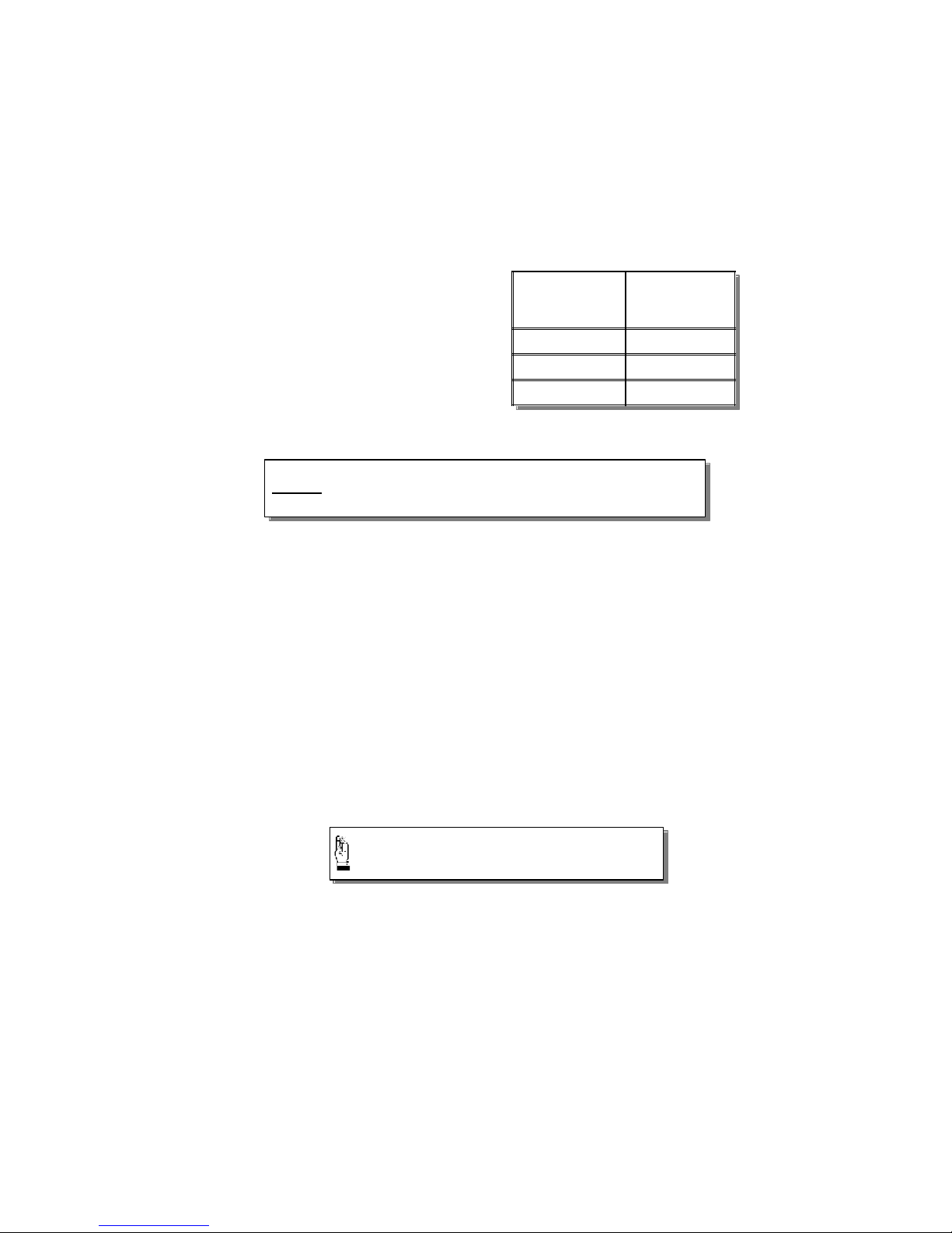
Also, longer and/or thinner cables will reduce the efficiency of the
overallsystem,sinceexcessivepowerwillbedissipatedinthecabling.
For temporary operation at
reduced power levels, the
guidelines listed in Table 1 may
be followed, or you can use the
cable sizes in Table 6.
Ideally, the cables should be no
more than 4 ft (1.5m) long. See
table 2 for a pictorial
representation of the wire
gauges.
Strip approximately 1/2” (1.25cm) of insulation from the ends of the
cables being connected to the inverter. Attach 5/16” ring terminals
to the ends of the wires to be attached to the DC terminals on the
Portawattz 3000. The ring terminals should be crimped with a proper
crimping tool.
Another option is to use Ilsco, or equivalent, box-lug terminals
(available at electrical parts suppliers). The bare cable end can then
be inserted into the lug terminal.
The other ends of the cables, which are connected to the power
source, must be terminated with lugs or other connectors that allow
a secure, low resistance connection to be made to the power source.
For instance, if the power source is a battery, the cables must be
terminated with battery terminals that clamp to the posts on the
battery.
Max. Test Load
Power
Consumption for
Short Term Test
Min. Cable Size
(Copper material
only)
100 Watts #16 AWG
250 Watts #12 AWG
500 Watts #8 AWG
Table 1 - Temporary Load Wire Gauge
Chart
A solid, low resistance connection to the DC power
source is essential for proper operation.
CAUTION!
DONOT operate your inverter for more than 5 minutes or at a higher power
usingthese cable sizes. Refertotable 6.
7
4.3 Test Loads
Useonlyequipmentratedfor110-120volt,
60 Hz AC operation that has a power
consumption of 500 watts or less. We
recommend that you start with a relatively
low power load, such as a 100 watt lamp,
to verify your test set-up before trying high
power loads.
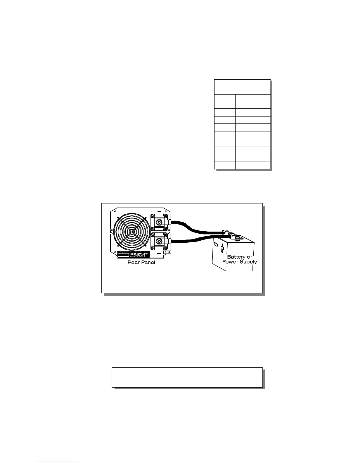
4.4 Connections
Follow the connection sequence described
below:
STEP 1 - EnsuretheON/OFFswitchon
the Portawattz 3000 is in the
OFF position. If the power
source is a DC power supply, switch it off as well.
STEP 2 - Connect the DC cables to the power input
terminals on the rear panel of the Portawattz 3000.
The Red terminal is positive (+) and the Black
terminal is negative (-). Tighten the wire
connections securely. (see figure 4).
STEP 3- Connect the cable from the negative (Black)
terminal of the Portawattz 3000 to the negative
terminal of the power source (battery or power
supply). Make a secure connection.
Figure 4. Connections to the Portawattz 3000
CAUTION!
Loose connectors result in excessive voltage drop and may cause
overheatedwiresandmeltedinsulation.
Table 2 - Wire size Chart
ALPHA Neoprene
Welding Cable
Wire Size
(AWG)
Overall Outside
Diameter
(inches/mm)
#6 0.35/8.89
#4 0.42/10.70
#2 0.48/12.19
#1 0.52/13.21
#1/0 0.58/14.77
#2/0 0.64/16.26
#3/0 0.70/17.78
#4/0 0.82/20.83

8
CAUTION!
Reverse polarity connection (positive to negative) will blow the fuses in the
Portawattz3000and may permanentlydamagetheunit. Damage caused by
reverse polarity connection is not covered by your warranty.
WARNING!
Youmayobserve a spark whenyoumakethe following connection sincecurrent
may flow to charge capacitors in the Portawattz 3000. Do not make this
connectioninthe presence of flammablefumes. Explosionorfire may result.
STEP 4 - Before proceeding further, carefully check that the
cable you have just attached connects the
negative terminal of the Portawattz 3000 to the
negative output terminal of the power source.
Power connections to the Portawattz 3000 must
be positive to positive and negative to negative.
STEP 5 - Connect the cable from the positive (Red terminal
of the Portawattz 3000 to the positive terminal of
the power source. Make a secure connection.
STEP 6 - If you are using a DC power supply as the power
source, switch it on. Set the ON/OFF switch on
the Portawattz 3000 to the ON position. Check
the meters and indicators on the front panel of
the Portawattz 3000. The battery voltage indicator
should indicate 11 to 14 volts, depending on the
voltage of the power source. If it does not, check
your power source and the connections to the
Portawattz 3000. The other indicators should be
off.
STEP 7 - SetthePortawattz 3000ON/OFFswitchto theOFF
position. The indicator lights may blink and the
internal alarm may sound momentarily. This is
normal. Plug in the test load now, but make sure
that it is first switched off.
STEP 8 - Set the Portawattz 3000 ON/OFF switch to the ON
position and turn the test load on. The Portawattz
3000 should supply power to the load. If it does
not, refer to the troubleshooting section of this
manual. If you plan to measure the output voltage
of the Portawattz 3000, refer to Section 2.2 of this
manual.

9
5 Permanent Installation
5.1 Where to Install
The Portawattz 3000 should be installed in a location that meets the
following requirements:
• Dry - Do not allow water to drip or splash on the Portawattz
3000.
•Cool - Ambient air temperature should be between 0ºC and
25ºC (32ºF and 77ºF). The cooler the better.
• Ventilated - Ensure that the unit is in a compartment that is
ventilated, and that you allow at least 1 inch
(2.5cm) of clearance around the Portawattz 3000
for air flow. Ensure that ventilation openings on
the front and rear of the unit are not obstructed.
• Safe - Do not install the Portawattz in the same compartment
as batteries or in any compartment capable of storing
flammable liquids such as gasoline (see warning
below).
• Close to Battery - Install as close to the battery as possible in
order to minimize the length of cable
required to connect the inverter to the
battery,butnotinthesamecompartment.
It is better and cheaper to run longer AC
wires than longer DC cables, because of
the much lower currents in the AC wires.
Mount the Portawattz on a flat surface using the mounting flanges on
the front and rear panels. Mounting hardware should be corrosion
resistant and #10 or larger. The Portawattz may be mounted
horizontally or vertically.
CAUTION!
To reduce fire hazard, do not cover or obstruct ventilation openings. Do not
install the Portawattz 3000 in a zero-clearance compartment. Overheating
mayresult. WARNING!
Thisequipmentcontainscomponentswhichtendtoproducearcsorsparks.
To reduce risk of fire or explosion do not install in compartments containing
batteriesorflammablematerialsorinlocationswhichrequireignitionprotected
equipment.
10
5.2 Battery
The battery you use strongly affects the performance you can expect
from your Portawattz 3000. It is important to connect the Portawattz
3000 to the correct size and type of battery. The following information
will help you select the appropriate batteries for your application.
5.2.1 Battery type
The lead-acid battery which is probably most familiar is the
starting battery in your automobile. An automotive starting
battery is designed to deliver a large amount of current for a
short period of time (so it can start your engine). Only a small
portion of the battery’s capacity is used when starting the engine
and it is quickly recharged by the running engine. It is not
designed for repeated charge-discharge cycles where the
battery is almost completely discharged and then recharged.
If it is used in this kind of deep discharge service, it will wear
out very rapidly.
Deep-cycle lead-acid batteries are designed for deep discharge
service where they will be repeatedly discharged and
recharged. They are marketed for use in recreational vehicles,
boats, and electric golf carts so you may see them referred to
as RV batteries, marine batteries, or golf cart batteries.
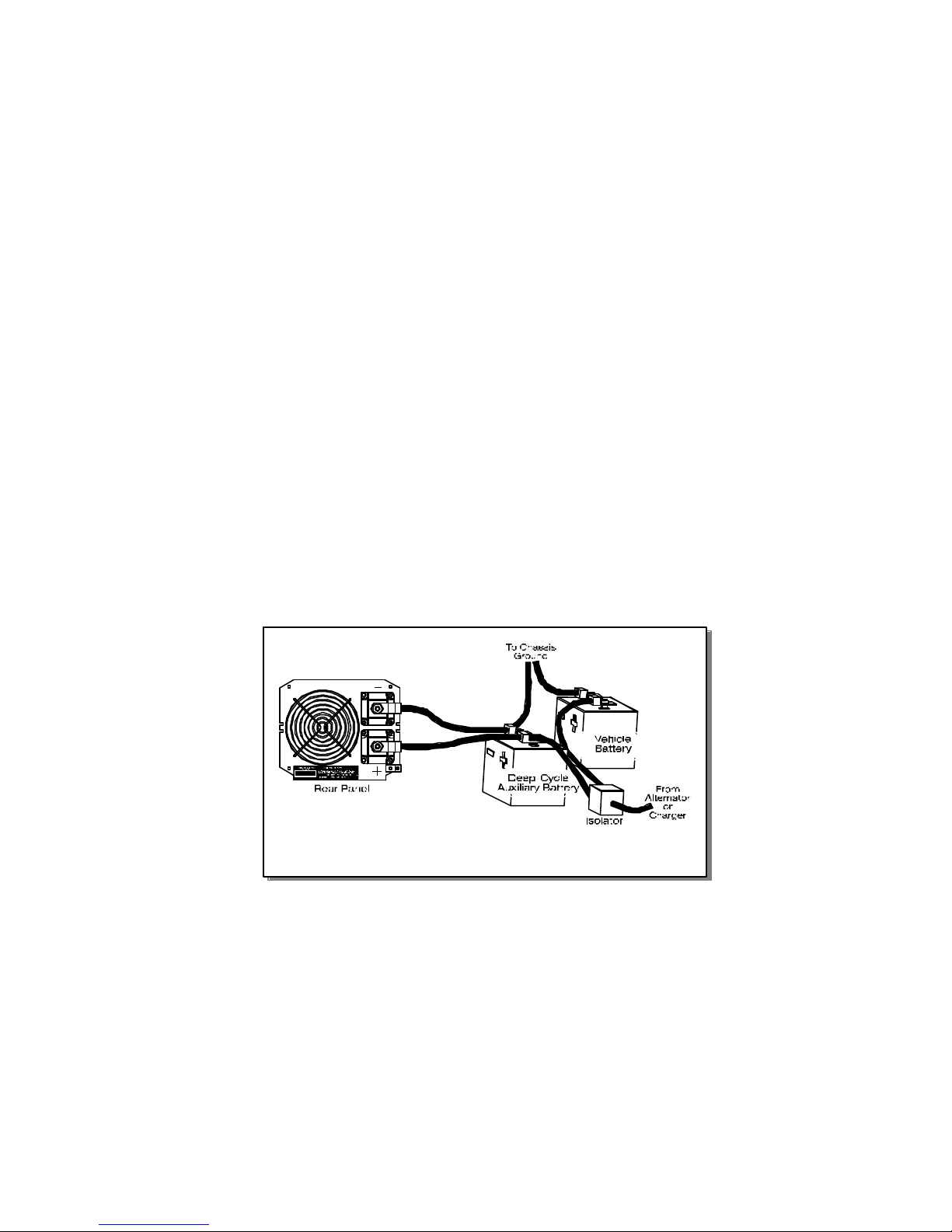
For most applications of the Portawattz 3000, Statpower
recommends that you use one or more deep-cycle batteries
that are separated from the starting battery in your vehicle by a
batteryisolator. Abatteryisolatorisasolid-stateelectroniccircuit
which allows equipment to be operated from an auxiliary battery
without danger of discharging the vehicle’s starting battery.
During vehicle operation, the battery isolator automatically
directs the charge from the alternator to the battery requiring
Figure 5 - Configuration for Medium-Duty Applications

11
the charge. Battery isolators can be obtained at marine and RV
dealers and most auto parts stores.
If your application involves relatively low power loads (i.e. power
consumption of 300 watts or less) and relatively short operating
times before recharging (one hour or less), you may connect
the Portawattz 3000 directly to the vehicle starting battery.
5.2.2. Battery Sizing
There are a number of different standards for rating battery
energy storage capacity. Automotive starting batteries are
normally rated by cranking amps. This is not a relevant rating,
for continuous use. Deep-cycle batteries are rated either by
reserve capacity in minutes or by ampere-hour capacity.
Battery reserve capacity is a measure of how long a battery
can deliver a certain amount of current - usually 25 amperes.
For instance, a battery with a reserve capacity of 180 minutes
can deliver 25 amperes for 180 minutes before it is completely
discharged.
Ampere-hour capacity is a measure of how many amperes a
battery can deliver for a specified length of time - usually 20
hours. For example, a typical marine or RV battery rated for
100 ampere-hours can deliver 5 amperes for 20 hours (5
amperes x 20 hours = 100 amp-hrs).
Actual battery capacity decreases as discharge current
increases. A battery rated at 100 ampere-hours which can
deliver 5 amperes for 20 hours, may deliver 20 amperes for
Figure 6. Connection for Light-Duty Applications
CAUTION!
ThePortawattz3000mustbeconnectedonlytobatterieswithanominaloutput
voltage of 12 volts. The Portawattz 3000 will not operate from a 6 volt battery,
andwill be damagedif it isconnected to a24 volt battery.

12
only 4 hours, resulting in an actual capacity of 80 ampere-hours.
For this reason, it is difficult to compare rated ampere-hour
capacity with battery reserve capacity. For example a battery
with a reserve capacity of 180 minutes has the following
calculated ampere-hour capacity:
However its actual ampere-hour rating will be closer to 100
ampere-hours because it is
rated at the discharge current
required to get 20 hours of
operation (about 5 amperes).
To determine the battery
capacity you require, follow
these steps:
STEP 1 - For each piece of equipment you will be operating
from the Portawattz 3000, determine how many
watts it consumes. This can normally be found
on a label on the product. If only the current draw
is given, multiply the current draw by 115 to get
the power consumption in watts.
STEP 2 - For each piece of equipment you will be operating
from the Portawattz 3000, estimate how many
hours it will operate between battery charging
cycles.
STEP 3 - Calculate total watt-hours of energy consumption,
total hours running time, and average power
consumption as in the following example:
STEP 4 - Using Table 3, find the battery size that will give
you the required operating time at the calculated
average power consumption. For instance, from
the example below, the required operating time is
6 hours and the average power consumption is
180 min.÷ 60 = 3 hrs
Therefore...
3 hr. x 25 amps = 75 amp-hrs
Equipment Power
Consumption
(Watts) Operating time Watt Hours
(Power x Operating Time)
TV & VCR 115 3 Hrs. 345
Sewing Machine 150 1 Hr. 150
Waterpik 90 0.25 Hrs. (15 Min.) 22.5
Blender 300 0.25 Hrs. (15 Min.) 75
Coffee Maker 750 0.3 Hrs. (18 Min.) 225
Coffee Grinder 100 0.2 Hrs. (12 Min.) 20
Microwave Oven 1500 0.5 Hrs. (30 Min.) 750
Washing Machine 1500 0.5 Hrs. (30 Min.) 750
TOTAL 6.0Hrs. 2337.5 watt-hours
Table 3

13
387 watts. From the chart, the smallest battery
size which will give more than 6 hours of operation
at a power level between 300 and 400 watts are
two 400 amp-hr. batteries in parallel, which offers
between 10 and 12 hours of operating time.
When sizing your battery, be conservative. More capacity is
better since you will have more reserve capacity, and your
battery won’t be discharged as deeply. Battery life is directly
dependent on how deeply the battery is discharged. The
deeper the discharge, the shorter the battery life. Ideally, the
number of ampere-hours consumed by your loads before
recharging the battery should be no more than 50% of the
battery’s rated capacity.
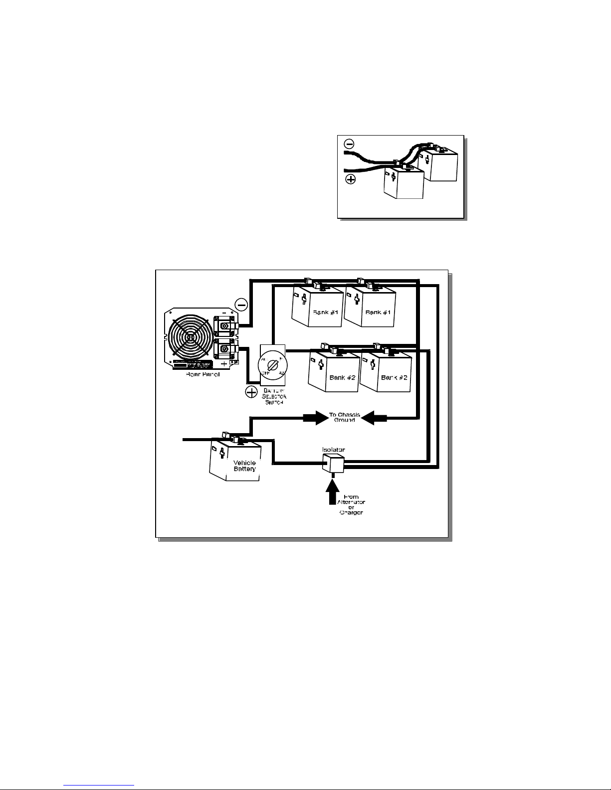
5.2.3. Using Multiple Batteries
To obtain sufficient battery capacity you may need to use more
than one battery. Two identical batteries can be connected +
to + and - to - in a parallel system that doubles capacity and
maintains the voltage of a single battery. Do not connect
batteries from different manufacturers, or with different amp-hr
ratings, in parallel - decreased battery life may result (see Figure
7).
12 volt Ampere-Hours Consumed = Watt-hours ÷ 10
= 2337 ÷ 10
= 234 ampere-hours
Average Power Consumption = 2337 watt-hrs ÷ 6 hours
= 390 watts
Table 4 - 12 Volt Battery Sizing Chart
Inverter
Ouput
Power
(Watts)
Typical Load
Battery Size
BCI Group Size 22NF 24 27 8D Dual 8D's
Reserve
Capacity 90 min. 140 min. 180 min. 400 min. 900 min.
AMP-Hrs. 50 75 100 200 400
50 Stereo System Operating Time 9 Hrs. 14 Hrs. 20 Hrs. 40 Hrs. 80 Hrs.
100 19" Colour TV Operating Time 4 Hrs. 6 Hrs. 10 Hrs. 20 Hrs. 40 Hrs.
200 Computer System Operating Time 2 Hrs. 3 Hrs. 4.5 Hrs. 10 Hrs. 20 Hrs.
300 Blender Operating Time 1.3 Hrs. 2.2 Hrs. 3 Hrs. 6 Hrs. 12 Hrs.
400 Power Drill Operating Time 1 Hr. 1.5 Hrs. 2 Hrs. 4.5 Hrs. 10 Hrs.
600 Small Coffee Maker Operating Time N.R. N.R. 1 Hr. 2.5 Hrs. 6 Hrs.
800 Small Microwave Operating Time N.R. N.R. N.R. 1.5 Hrs. 4 Hrs.
1000 Toaster Operating Time N.R. N.R. N.R. 1 Hr. 3 Hrs.
1500 Full Size Microwave Operating Time N.R. N.R. N.R. 0.5 Hrs. 2 Hrs.
2500 Hair Dryer & Washing
Machine Operating Time N.R. N.R. N.R. 0.2 Hrs. 0.8 Hrs.
N.R. = Not Recommended
14
If you are using different
batteries, or need to use more
than two batteries, we
recommend that you set up
two separate battery banks
and use them alternately.
Battery selector switches are
available from marine and RV
dealers which allow you to
select between two banks of batteries, or use both in parallel,
or disconnect both from the load (see Figure 8).
5.2.4. Battery Tips
1. With the exception of sealed batteries, lead-acid batteries
emit hydrogen and oxygen gases, and sulfuric acid fumes
when recharging. Vent the battery compartment to prevent
accumulation of these gases, and do not install electronic
or electrical equipment in the battery compartment. Do
not smoke or carry an open flame when working around
batteries.
Figure 7. Parallel Batteries
Figure 8. Configuration for heavy-duty Applications

15
2. The capacity of lead-acid batteries is temperature sensitive.
Battery capacity is rated at 25ºC (77ºF). At -20ºC (0ºF) the
ampere-hour capacity will be about half the rated capacity.
3. Do not leave batteries in a discharged state for more than a
day or two. They will undergo a chemical process called
sulfation which can permanently damage the batteries.
Also, batteries will self-discharge over a period of 3 to 6
months, so they should be periodically recharged even if
they are not being used.
4. If your batteries are not the “maintenance-free” type, check
the electrolyte fluid level at least once a month. Use only
distilled water to replenish the electrolyte fluid. Excessive
fluid loss is a sign of overcharging.
5. Connections to battery posts must be made with permanent
connectors that provide a reliable, low resistance
connection. Do not use “alligator” clips. Clean the
connections regularly and prevent corrosion by using an
insulating spray coating or Vaseline.
6. Battery state of charge can be
measured with a hydrometer or,
more easily, with a voltmeter. Use
a digital voltmeter that can display
tenths or hundredths of a volt
when measuring 10 to 30 volts.
Make your measurements after
the (12 volt) battery has not been
chargedordischargedforseveral
hours. For a deep-cycle battery
at 25ºC (77ºF), refer to table 5.
5.2.5. Alternators and Charging Systems
A good charging system is important for the health of your
batteries. Poor recharging methods can quickly damage your
batteries. When possible, recharge your batteries when they
are about 50% discharged. This will give you much longer
battery cycle life than recharging when the batteries are almost
completely discharged. The Statpower
TRUECHARGE
TM
family
of battery chargers are designed to maximize your battery’s
performance and useful life (see your Statpower dealer for more
details).
The charging system should be capable of delivering a charging
current equal to 25% of the ampere-hour capacity of your
battery. For instance, if you have a 200 ampere-hour battery,
the charging system should be able to deliver 50 amperes.
The charging system must also be able to charge each 12 volt
Battery
Voltage State of
Charge
12.7-12.9 100%
12.5-12.6 80%
12.3-12.4 60%
12.1-12.2 40%
11.9-12.0 20%
Table 5 - Battery Charge
State.

16
battery up to approximately 14.4 volts and then drop back to a
“float” voltage of 13.5 to 14 volts (or shut off).
A typical engine alternator may not be able to meet these
requirements if large capacity batteries are used. Alternators
are typically rated for the current they can deliver when they
are cold. In actual use, alternators heat up and their output
current capability drops by as much as 25%. Thus standard
alternators with ratings of 40 amperes to 105 amperes will only
deliver a maximum of 30 to 80 amperes in actual use and will
deliver even less as battery voltage rises. Many alternators
cannot produce more than 13.6 volts when they are hot. As a
result, a standard alternator may not be able to charge a large
battery quickly and completely.
One solution is to install an alternator controller that will bypass
the voltage regulator and boost the alternator’s output voltage
during charging. This will increase the alternator’s charging
rate at higher battery voltages and ensure more rapid and
complete charging. Alternator controllers are available from
marine product dealers.
Another solution is to install a high-output alternator. Heavy-
duty alternators rated from 100 amperes to 140 amperes are
available from RV and marine dealers, and auto parts suppliers.
These alternators are designed to directly replace standard
alternators but produce the higher current and higher voltage
required to charge multiple battery systems.
When recharging from AC power, use a good quality marine
battery charger or RV converter that meets the requirements
specified above. Do not use chargers intended for occasional
recharging of automotive starting batteries; these chargers are
not intended for continuous use.
Your batteries may also be recharged from alternative energy
sources such as solar panels, wind, or hydro systems. Make
sure that you use the appropriate battery charge controller for
your energy source.
Do not operate the Portawattz 3000 directly from a charging
source such as an alternator or solar panel. The Portawattz
must be connected to a battery or a well-regulated, high-current
DC power supply to work properly.
5.3 Battery Cables
Proper wire and wiring is very important for the safe and proper
operation of the Portawattz 3000. Because the Portawattz 3000 has
a low voltage, high current input, low resistance wiring between the
Table of contents
Other Statpower Inverter manuals


Popular Inverter manuals by other brands

Vector
Vector MAXX SST 1000 VEC049 owner's manual

MARSS
MARSS Solar Defender ALM-6814 Installation and programming manual

Sungrow
Sungrow SG100KU installation manual

Solectria Solar
Solectria Solar Rapid Shutdown Installation and operation guide

Sungrow
Sungrow SG75CX-P2 user manual

Danfoss
Danfoss VACON NX FI6 operating guide


Powfuture
Powfuture Venus 3000TL user manual

Mitsubishi Electric
Mitsubishi Electric FR-F700PJ Series manual

HuaYao
HuaYao S650 Universal instruction manual

DORNA TECHNOLOGY
DORNA TECHNOLOGY H300 Series user manual

Hitachi
Hitachi HFC-VWE2 SERIES instruction manual

Mitsubishi Electric
Mitsubishi Electric 700 Series INSTALLATION GUIDELINE