IBS US40 User manual

IBS Intelligent Battery System GmbH
Seestrasse 24, CH-3600 Thun, Schweiz
Tel: +41 33 221 06 16
Fax: +41 33 221 06 17
E-Mail: info@ibs-tech.ch
IBS-USG4_en_v2.0.3.doc
last Update 28.8.2018
1
Ultra Sine Inverter (US)
Generation 4 (G4)
User Guide

2
Table of Contents
Product description.....................................................................................................................................3
Applications ............................................................................................................................................3
Data........................................................................................................................................................3
Standardization.......................................................................................................................................3
Special features......................................................................................................................................4
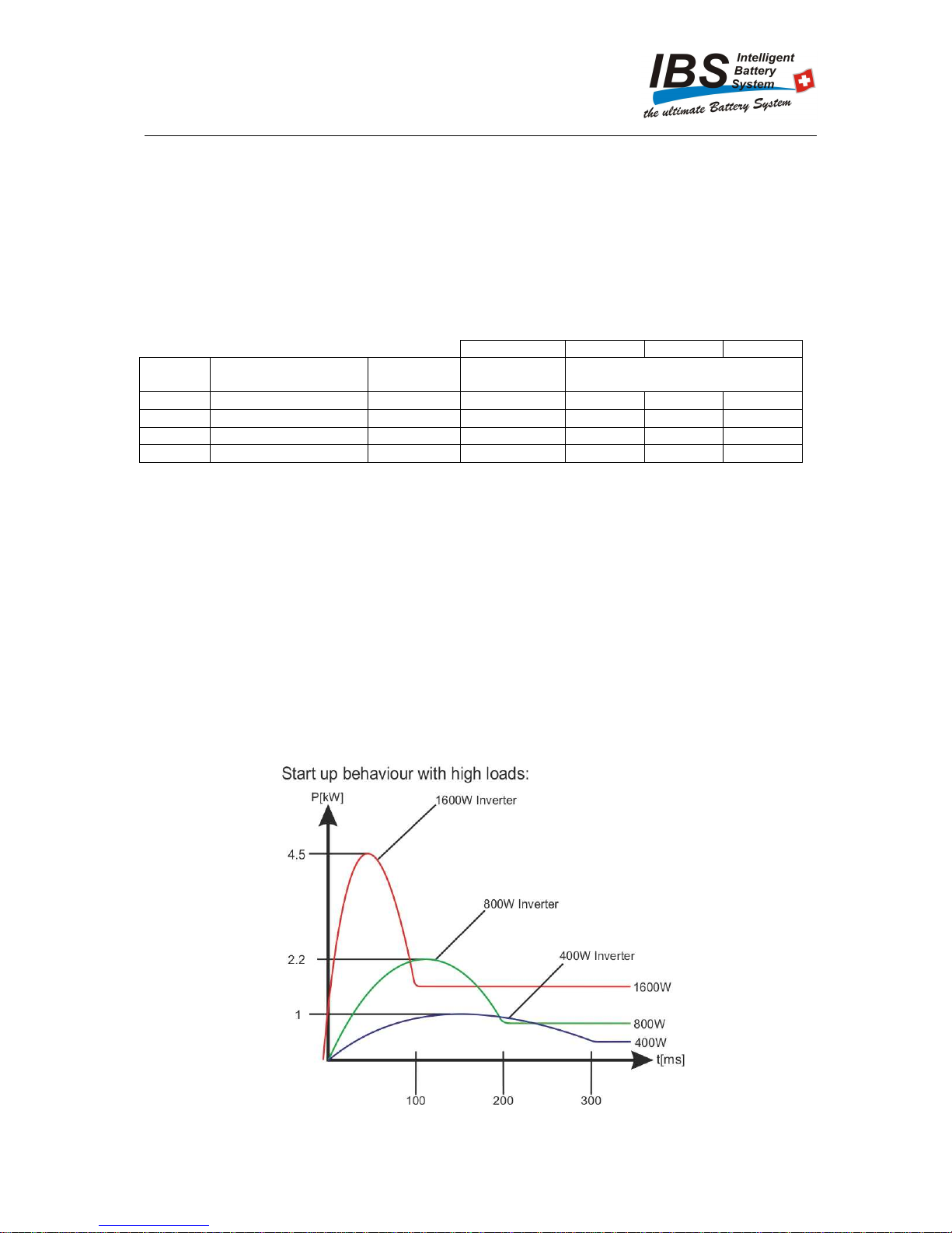
DSC (Dynamic Surge Control) ...........................................................................................................4
DSC Classes ......................................................................................................................................4
Protection of deep discharge oft he battery........................................................................................4
Performance...........................................................................................................................................4
Warning ......................................................................................................................................................5
Supplied content.........................................................................................................................................5
Informations................................................................................................................................................6
Front view...............................................................................................................................................6
US160 / US80.....................................................................................................................................6
US40...................................................................................................................................................6
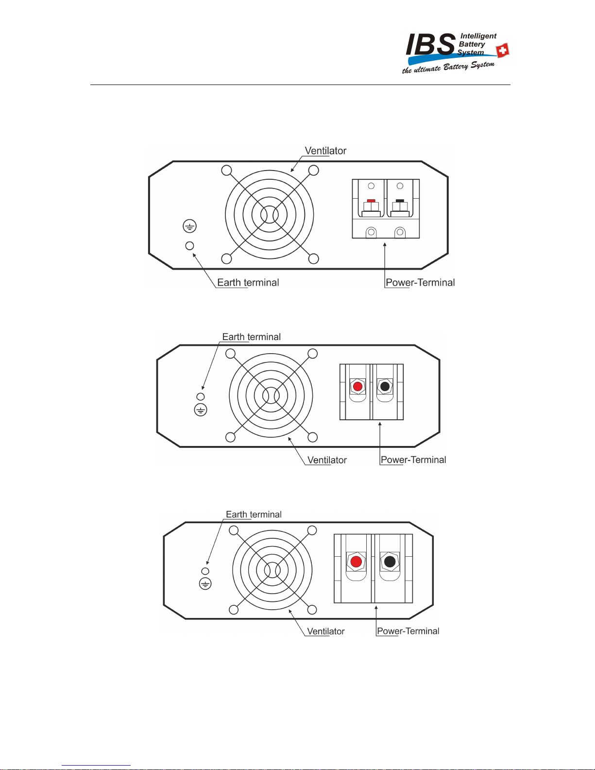
Rear view................................................................................................................................................7
US160.................................................................................................................................................7
US80...................................................................................................................................................7
US40...................................................................................................................................................7
Installations.................................................................................................................................................8
Recommended cable cross section .......................................................................................................8
Recommended battery capacity.............................................................................................................8
External fuse...........................................................................................................................................8
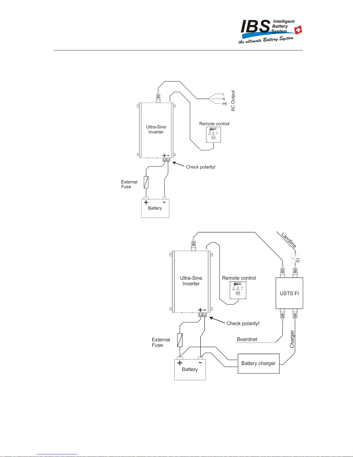
Installation Steps ....................................................................................................................................9
Wiring..................................................................................................................................................9
Grounding.........................................................................................................................................10
Connecting the consumer device.....................................................................................................10
Connectors for device..................................................................................................................10
Commissioning the unit............................................................................................................................10
Connect the remote control..................................................................................................................10
Switching on the appliance...................................................................................................................10
Activating / deactivating standby..........................................................................................................10
Status Display...........................................................................................................................................11
Status....................................................................................................................................................11
Operating Modes..................................................................................................................................11
Error display .........................................................................................................................................11
Troubleshooting....................................................................................................................................11
Power display .......................................................................................................................................12
Assembly..................................................................................................................................................13
Housing dimensions.............................................................................................................................13
Attaching the mounting feet..................................................................................................................16
Fitting....................................................................................................................................................17
Please note...............................................................................................................................................18
Specifications ...........................................................................................................................................18
Technical specifications........................................................................................................................18
Accessoires ..............................................................................................................................................18
Instructions for the electrical supply .........................................................................................................21

3
Product description
The new IBS Ultra Sine inverters for island operation in mobile or stationary applications produce pure
sine wave alternating voltage with 230VAC / 50Hz from 12V or 24VDC battery voltage. Latest
technology allows the construction of lightweight and compact inverters. High-frequency hi-tech
transformers with a powerful software-controlled IGBT transistor bridge guarantee impressive
performance. The latest generation has reduced its own consumption by 30% to 1.2A @ 12.3V / 1.1A
@ 24.6V, which is ideal for use in insulated solar systems. Consumers such as hairdryers, vacuum
cleaners, coffee machines, hand-held machines, computers, laser printers, measuring instruments,
medical devices can be operated in most cases.
Applications
•Motorhomes, Camper
•4WDs / Expedition / Rallye
•Yachting
•Solar (island installations)
•Commercial and industrial use
•Energy back-up for computers, communications and medicine
•Mobile power for craftsmen
Data
Technologie High frequency
Dual processor
Galvanic separation
Remote Control RP03 Available as an option
Monitoring Over- / Undervoltage
Overtemperature, overload
Short circuit, current limiter
Reverse polarity / fuse
Dynamic Surge Control (DSC)
Housing Aluminum, IP40
Cooling Cooling plates / cooling tunnel, fan, µC monitored
Standardization
Low Voltage Directive
2006/95/EC
-EN60950:2005
EMV
guideline
2004/108/EC
-EN 61000-6-3:2006
-EN 61000-6-1:2005
RoHS
guideline
2002/95/EC

4
Special features
DSC (Dynamic Surge Control)
The inverter is equipped with dynamic surge control. The more battery capacity or charging current
support (alternator) is available, the larger consumer devices can be started. If the starting current
exceeds the safe value, it results in a safety cut-off (red error LED flashes), reset by switching the
inverter off and on again.
DSC Classes
Inverter
typ
e
US160 US80 US40
Classe Input voltage Ue
dUe
at
load Time allowed Power output
S1
>13.5V/ >27.0V 2.7 V 800 ms 3.8 kW 1.9 kW 1.0 kW
S2
13.0-13.5V/26-27V 2.0 V 400 ms 3.5 kW 1.7 kW 0.8 kW
S3
12.3-13.0V/24.6V-26V
1.5 V 200 ms 3.2 kW 1.6 kW 0.7 kW
S4
<12.3V/24.6V 1.2 V 100 ms 3.0 kW 1.5 kW 0.6 kW
Protection of deep discharge of the battery
The inverter is equipped with an intelligent, current-dependent deep-discharge circuit. Switch-off value
11.8V / 23.6V, re-activation 12.3V / 24.6V. Immediate shutdown when battery drops below 10.5V /
21.0V.
Performance
The IBS inverters are very powerful, as long as the batteries provide the necessary energy. Use as
much charged, high-performance batteries as possible. Recommended battery capacities
see P. 8. If the inverter is used for a long period, allow the engine to run for support (continuous
currents up to 150A and starting currents up to 350A / 180A are possible). If charging support is
provided by alternator or solar / charger (U> 13.0V /> 27V), the starting power according to DSC class
S1 is available.
Abb. 1 Chart peak power

5
Warning
Have the wiring carried out by a qualified technician. Before the Connection is started, make sure that
all cables and connections are voltage-free. Short circuits and polarity reversal can lead to serious
damage to the battery, the Ultra Sine inverter and the electrical installation. Fuses cannot prevent
damage caused by polarity reversal. Such damages are not included in the warranty.
Inverter output cannot be connected to the public network! (Use US-TS for automatic landline / inverter
switching)
Never insert objects through the openings and ventilation slots of the device!
Supplied content
•US160/80/40
•Mounting feet

6
Informations
Front view
US160 / US80
Abb. 2 Front view US160/80
US40
Abb. 3 Front view US40

7
Rear view
US160
Abb. 4 US160 Rear view
US80
Abb. 5 US80 Rear view
US40
Abb. 6 US40 Rear view

8
Installations
Recommended cable cross section
When using a thinner cable cross-section than recommended, large losses and dangerous heating can
occur in the connection cable. This may cause the Ultra Sine inverter to fail its full performance.
Model
US40
US80
US160
Voltage value
12V 24V 12V 24V 12V 24V
Min. cable cross section
16 mm
2
10 mm
2
25mm
2
16mm
2
50mm
2
35mm
2
Connection to the devi
ce
M6 M6 M8
Data refer to the copper cross-section of the cables!
Recommended battery capacity
High loads caused by an inverter system need sufficient available battery capacity. To ensure that the
required application has enough energy, refer to the following table for recommended battery
capacities.
L
oad
Capacity
of
12V System
Capacity
of
24V System
< 500 W 60 Ah 2 x 30 Ah
> 500 W 80 Ah 2 x 40 Ah
> 1000 W 100 Ah 2 x 50 Ah
> 1500 W 140 Ah 2 x 70 Ah
External fuse
The value fort he external fuse can be found in the following table.
Model
Battery voltage
Fuse to use
US40 12 V 40A
24 V 20A
US80 12 V 80A
24 V 40A
US160 12 V 150A
24 V 80A

9
Installation Steps
Wiring
Abb. 7 Cabling normal use
Abb. 8 Cabling with US transferswitch
Warning: Ensure correct polarity! Closing the circuit can cause a spark! Never connect the AC output of
the inverter to the public network!
Caution: When installing the USTS FI, please consult the manual for instructions and safety
instructions!
A main switch (S1) must be provided to allow emergency disconnection of incoming shore power
supply!
In mobile applications such as
travel trailers or yachts with a
possible landline, the two-230V
networks (inverter and landline
connection) may only be
connected via the US-TS FI
switch! The same applies if 230V
emergency generators are used!
For parallel IBS operation, use
the US-TS FI transfer switch.

10
Grounding
The grounding scheme of the US Inverter G4 is as follows:
Connecting the consumer device
Connectors for device
The Ultra Sine inverter is equipped with a socket according to IEC 60320-1 C13. A plug according to
IEC 60320-1 C14 must be used as a counterpart.
Commissioning the unit
Connect the remote control
Plug the connection cable of the remote control into the remote control plug.
A non-crossed 8-pin RG45 cable must be used.
Switching on the appliance
To switch the device on and off, press the on / off button on the front of the device or the button on the
RP03 remote control.
Activating / deactivating standby
To activate or deactivate standby, press the on / off button on the front of the device or the button on the
remote RP03 remote for 3 seconds until the middle LED (orange) lights up (continuous operation active)
or extinguishes (standby active).

11
Status Display
The three LEDs on the front of the unit or the RP03 connected to the remote control, indicate the status,
operating modes, and faults.
Status
The green LED indicates the current operating state.
Statut
Gr
een
LED
Description
1
Switched off
2
Operational
3
In standby
Operating Modes
The yellow LED indicates the operating mode.
Mode
Yellow
LED
Description
1
Standby-mode
2
Continuous operation mode
Error display
The red LED indicates faults.
Error
R
ed
LED
Description
0
Without Error
1
Over- / Under voltage
2
Over temperature
3
System fault / fuse defective / overcurrent
4
Short circuit / overload
Troubleshooting
Error
Triggered by
Resetting by
1
Delayed:
Voltage lower than 11.8V / 23.6V
Or higher than 15.5V / 31.0V
Immediately:
Voltage lower than 10.5 V / 21.0 V
Voltage higher than 13.1V / 26.2V
or lower than 14.5 V / 29.0 V
Voltage higher than 13.1V / 26.2V
2 If the temperature is too high at the heat sink. f the heat sink is below a minimum
temperature.
3 If too much current or a faulty fuse has been
detected.
Check the load, the polarity and switch the
inverter off and then on again. If the fuse is
defective, contact IBS.
4 Short circuit at output or too long load with
high power. Check the load and switch the inverter off and
then on again.

12
Power display
The US80 and US160 have an output power indicator. The number of luminous LEDs indicates the
current output power.
Abb. 9 Power display US160 (left) and US80 (right)

13
Assembly
Housing dimensions
Abb. 10 US160 Housing dimensions

14
Abb. 11 US80 Housing dimensions

15
Abb. 12 US40 Housing dimensions

16
Attaching the mounting feet
Abb. 13 Horizontal alignment of mounting feet
Abb. 14 Vertical alignment of mounting feet
Screw the mounting feet to the intended positions using the screws supplied. Only the included screws
may be used. The tightening torque is 1.1 Nm.

17
Fitting
•Mount the unit with the mounting feet on a surface. Mounting is possible on a surface, on a
sidewall or upside down.
•The ventilation slots and the fan must not be obstructed, so that the warm air, which is
generated during operation, can escape unimpeded. Do not install in a small enclosed space,
ensure air circulation.
•Ensure that no objects, dust or dirt can enter the interior of the unit through the ventilation slots
or fan.
•Avoid any contact with water, moisture or rain. Humidity: 0-95%, non-condensing.

18
Please note
In order to guarantee the perfect operation of your IBS Ultra Sine inverter, please note the following
points:
1. Inverter and battery voltage must be the same. Operation of a 12V device at 24V leads to
destruction of the inverter.
2. The battery must be charged. If an inverter is operated with high power, the battery can be
discharged quickly. If the battery voltage is too low, the inverter switches off and can only be
switched on again after charging the battery.
3. High continuous load in case of insufficient cooling can lead to an emergency shutdown. The
fan supports cooling depending on current and temperature.
4. Observe the same safety regulations as when using the 230V public network. When using the
inverters, an additional fuse of 150A (12V) / 80A (24V) is recommended directly at the battery
connection or circuit breaker (automatic fuse).
Specifications
Technical specifications
US40 US80 US160
12V 24V 12V 24V 12V 24V
Input voltage 10.5V –
15.5V 21.0V –
31.0V 10.5V –
15.5V 21.0V –
31.0V 10.5V –
15.5V 21.0V –
31.0V
Rated capacity 400 W 800 W 1600 W
Short-term performance 1000 W 2200 W 4500 W
Output voltage 230V / 50Hz
Print quality IPC3
Temperature range - 20 °C bis + 40 °C
Standby consumption <0.5 W
Standby void detection > 15 W – 30 W > 15 W – 30 W > 15 W – 30 W
Weight 1.7 kg 3.6 kg 5.5 kg
Efficiency 90 / 93 % 90 / 93 % 90 / 93 %
Accessoires
RP03 Remote Control
US-TS Transferswitch for automatic landline / US switching

19
Notes

20
This manual suits for next models
2
Table of contents