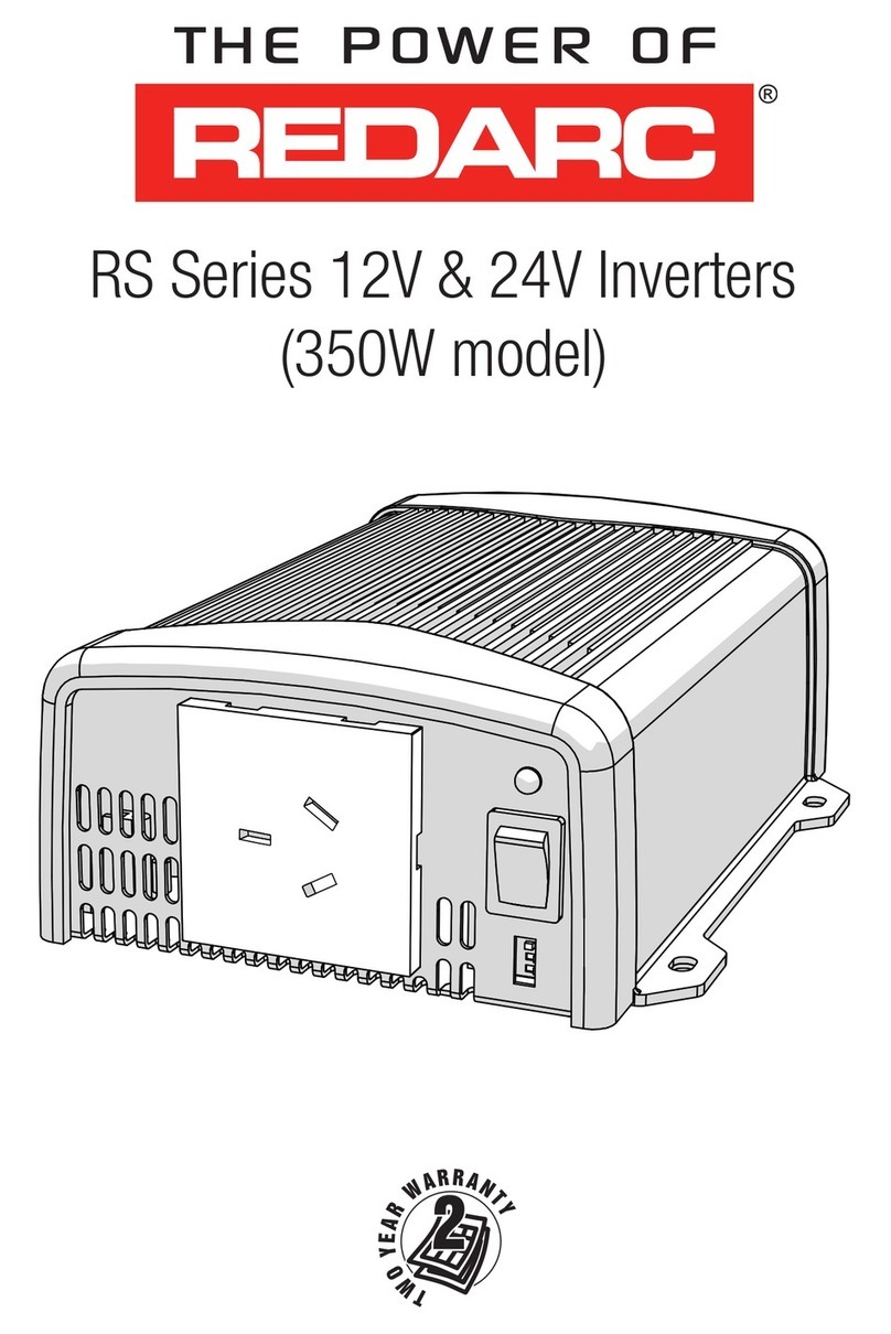
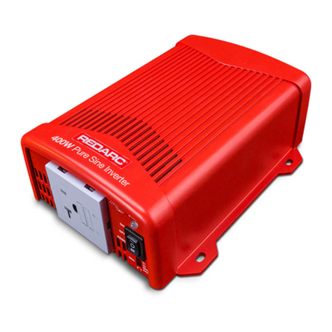
Redarc RS3 Series User manual

RS3 Pure Sine Wave Inverter
MODELS:
R-12-1200RS3
R-12-2000RS3
R-12-3000RS3
R-24-1200RS3
R-24-2000RS3
R-24-3000RS3

2
RS3 Pure Sine Wave Inverter
PRODUCT FUNCTION
The REDARC RS3 range of Pure Sine Wave Inverters have
been designed to provide safe, efcient, and reliable 230VAC
power for your electronic devices in remote environments.
Built with safety in mind, the RS3 Inverters feature a residual
current circuit breaker with overcurrent protection (RCBO).
This will safely and effectively shut-down power to a
connected load in an over current or short circuit event whilst
also protecting against electrocution, making it a safe and
reliable choice for a wide range of applications.
Available in 12V and 24 V input variants, the RS3 range is
suitable for installations in a range of applications including
caravans, camper trailers, motor homes, truck sleeper cabs,
4x4's and commercial vehicles.
RS3 Inverters are also equipped with an inbuilt Automatic
Transfer Switch (ATS) to automatically switch from battery
power to mains power when available.
Discover power and convenience on the go like you've never
experienced before with 1200W, 2000 W, 3000 W models
available to power appliances such as laptops, power tool
battery chargers, coffee machines, kettles, induction cookers
and toasters.

3
CONTENTS
WARNINGS AND SAFETY INSTRUCTIONS 4
1 FRONT PANEL OVERVIEW 6
1.1 Main Switch 7
1.2 Status LED 7
1.3 Function Switch 7
2 REAR PANEL OVERVIEW 11
2.1 Communication and Remote Interface 12
2.2 Remote Control Terminal 12
2.3 Chassis Ground 13
3 INSTALLATION 14
3.1 Cable and Fuse Requirements 14
3.2 Lug Requirements 15
3.3 Mounting 16
3.4 Ventilation Fan 17
3.5 Safety Before DC Input Cable Connections 17
3.6 DC Input Cable Connections 19
3.7 Turning the Inverter on 20
3.8 AC Input and output Connections 21
3.9 Maintenance 21
4 SPECIFICATIONS 22
4.1 1200 W Specifications 23
4.2 2000 W Specifications 24
4.3 3000 W Specifications 25
4.4 Dimensions 26
5 WARRANTY 27

4 | Warnings and Safety Instructions
WARNINGS AND SAFETY INSTRUCTIONS
SAVE THESE INSTRUCTIONS — this manual contains important safety instructions. Do not operate
the system unless you have read and understood this manual.
REDARC recommends that the Inverter referenced in this manual be installed by a suitably qualied
person.
Disclaimer: REDARC accepts no liability for any injury, loss or property damage which may occur from
the improper or unsafe installation or use of its products.
SAFETY MESSAGE CONVENTIONS
Safety messages in this manual include a signal word to indicate the level of the hazard as follows:
WARNING Indicates a potentially hazardous situation which could result in death or
serious injury to the operator or to bystanders.
CAUTION Indicates a potentially hazardous situation which may result in moderate or
minor injury to the operator or to bystanders.
NOTICE Indicates a situation that may cause equipment damage.
WARNING
Risk of electrical shock. Do not disassemble the inverter - the internal circuitry contains hazardous
voltages. Attempting to service the unit yourself may result in electric shock or fire and could void the
unit warranty.
Risk of electrical shock. Do not expose the inverter to rain, snow, spray, liquid or dust. Doing so may
result in damage to the inverter or other appliances installed in the system or result in electric shock or
fire.
Risk of electrical shock. Operation of the inverter without a proper ground connection may result in an
electrical safety hazard. Ensure proper ground connection is made during installation. For fixed and/or
transportable (vehicle) installations, install according to appropriate AS/NZS standard.
Risk of electrical shock. Before proceeding, carefully check that the inverter is not connected to any
batteries and that all cables are disconnected from any electrical sources.
Do not connect the output terminals of the inverter to an incoming AC source.
CAUTION
This appliance is not intended for use by persons (including children) with reduced physical, sensory
or mental capabilities, or lack of experience and knowledge, unless they are supervised or have been
instructed on how to use the appliance by a person responsible for their safety. Children should be
supervised to ensure that they do not play with the appliance.
Do not operate the inverter with damaged or substandard cabling. Selecting the wrong cable or fuse size
could result in harm to the installer or user and/or damage to the inverter or other appliances installed in
the system. The installer is responsible for ensuring that the correct cable and fuse sizes are used when
installing this inverter. Refer to Section 3.1 (page 14) for more information.
Ensure recommended torque values are observed and the DC Input connections to the Inverter are tight
(torque to 11.7–13Nm (9–10ft-lbs)). Any loose connections could result in overheating and can be a
potential hazard.

Warnings and Safety Instructions | 5
Some components in the inverter can cause arcs and sparks. Do not put batteries, ammable materials,
liquids, or anything that should be ignition–protected around the inverter. Doing so may result in re or
explosion.
Be extra cautious to reduce the risk of dropping a metal tool onto a vehicle battery. Doing so might cause
the battery to spark or might short-circuit the battery or other electrical parts that may cause an explosion.
Remove personal metal items such as rings, bracelets, necklaces, and watches when working with a
battery. A battery can produce a short-circuit current high enough to weld a ring or the like to metal,
causing a severe burn.
If battery acid contacts your skin or clothing, remove the affected clothing and wash the affected area of
your skin immediately with soap and water. If battery acid enters your eye, immediately ood the eye with
running cold water for at least 10 minutes and seek medical assistance immediately.
NEVER smoke or allow a spark or ame in vicinity of battery. This may cause the battery to explode.
Batteries are capable of providing very large currents in the case of a short circuit. A fuse must be installed
on the positive supply cable as close as practical to the battery. Failure to do so provides inadequate
protection against re in the case of a short circuit. Only use high quality copper cable and keep the cable
length short, refer to Section 3.1 (page 14) for more information.
NOTICE
Upon receipt, examine the box for damage. If you have found any damage on the box, please notify the
company you purchased this unit from.
Install the inverter in a well-ventilated area with reasonable clearance. Do not install the inverter in a
zero-clearance compartment or obstruct the ventilation openings. Doing so may result in the inverter
overheating and ultimately damage the inverter.
Reverse Polarity connection will blow the internal fuse and may damage the inverter permanently and could
void the warranty.
Do not operate appliances that may feed power back into the inverter. Damage to the inverter may occur
as a result.
The RS3 Inverters are tted with RCBO, which incorporates both a residual current device as well as a
circuit breaker. The RS3 Inverters comply with AS/NZS 4763 standard and can be used to power xed
wiring in accordance with AS/NZS 3001 when installed by a licensed electrician. A proper ground bond is
required for the RCD to work as intended, see page18 for more information.
Ensure that the frequency output of the inverter matches the frequency requirements of all loads attached
to the inverter. Attempting to use appliances that requires an AC frequency different to the inverter output
may result in damage to your appliances.
All RS3 Series Inverters are suitable for indoor use only.
When the ATS is passing grid power through the load(s), the RCD and over-current protection must be
provided by the 'shore power' supply (refer to Section 1.4 (page 10)).
When the ATS is passing through AC power from the AC Input connection, the integrated M.E.N.
connection (Main Earth Neutral - required for correct operation of the RCD) is not in circuit. The external
AC supply must provide the safety mechanism for the connected loads – consult a qualied electrician.

6 | Front Panel Overview
1 FRONT PANEL OVERVIEW
WARNING: Risk of electrical shock. Do not disassemble the inverter — the internal circuitry
contains hazardous voltages. Attempting to service the unit yourself may result in electric shock or fire
and could void the unit warranty.
3000W
1200W / 2000W
3
1
6
645
1
6
645
2
2
3
1Main Switch 4RCBO Safety Switch
2Status LED 5AC Input Interface
3Function Switch 6AC Output Interface

Front Panel Overview | 7
1.1 MAIN SWITCH
The 3-stage Main Switch is used to toggle the Inverter ON and OFF or to
select Remote Control mode. In the ON position, the inverter will be active,
and the Status LED will light up. In the OFF position, the Inverter will be
powered off and the Status LED will also be turned off.
In the REMO position, the Inverter will be switched ON and OFF via the REMOTE-RS connected to the
Remote Interface (RJ-11) or via the Remote Control Terminal (see Section 2.1).
1.2 STATUS LED
The Status LED displays the operating mode of the Inverter.
LED Flash Sequence Inverter Status
Constantly Lit Normal Mode
Quick Flash Input Voltage for 12 V is <11.0 V or >16.0 V
Input Voltage for 24 V is <22.0 V or >32.0 V
2 seconds lit, short
interruption
Over heating
Excessive load
Off Other fault or Unit is switched off
1.3 FUNCTION SWITCH
Figure 1: DIP Switch ON/OFF Positions
OFF
ON

8 | Front Panel Overview
S1 — DEFINING SETTINGS
Using the S1 DIP Switch you can choose between using the Inverter's default Voltage and
Energy-Saving Mode settings or using the settings dened by S2, S3 and S4 DIP Switches.
With S1 in the OFF position, by default the Inverter output is set to 240 V / 50 Hz with no power saving
mode.
Parameter S1 DIP Switch
Internal Default Setting OFF
DIP Switches S2 – S4 Enabled ON
S2 — SELECTING OUTPUT VOLTAGE
The S2 DIP Switch is used to set the output voltage of the Inverter.
Inverter Output Voltage S2 DIP Switch
230 V/50 Hz OFF
240 V/50 Hz ON
S3 AND S4 — SELECTING POWER-SAVING MODE
The S3 and S4 DIP Switches are used to set the conditions when the Inverter will operate in its Power-
Saving Mode. This mode reduces the power consumption of the Inverter by reducing the Standby
Current Consumption listed in Section 4 (page 22) for each model.
The Inverter operates in Power-Saving Mode if the required output power is below the set threshold. If
the required power exceeds this threshold, the Inverter will operate in Normal Mode.
The Power-Saving Mode behaviour is set by S3 and S4 as found in the following table:
Saving Mode DIP Switch S3 DIP Switch S4
Saving mode activated when load < 5 W
Normal mode activated when load > 5 W OFF OFF
Saving mode activated when load < 5 W
Inverter shutdown automatically after
20 minutes in saving mode.
Normal mode activated when load > 5 W
OFF ON
Saving mode activated when load < 45 W
Normal mode activated when load > 45 W ON OFF
Saving mode activated when load < 45 W
Inverter shutdown automatically after
20 minutes in saving mode.
Normal mode activated when load > 45 W
ON ON

Front Panel Overview | 9
OUTPUT POWER PERFORMANCE
Figure 2 displays the length of the time the
Inverter can sustain a given Output Power (Pout)
across the input voltage range for 12V and 24 V
variants.
Figure 2: Input Voltage vs. Output Power
VDC
16.5
(33)
12.0
(24)
10.5
(21)
200%
115%
100%
0%
Pout
Continuous
10 min.
3 min.
< 3s
POWER VS TEMPERATURE
PERFORMANCE
Figure 3 shows the derating of the
Inverter output when ambient temperature
exceeds 40°C (104°F), as well as the
minimum operating ambient temperature
of –20°C (–4°F).
Figure 3: Power vs. Temperature
Temperature °C (°F)
–20˚C
(–4˚F)
0˚C
(32˚F)
40˚C
(104˚F)
60˚C
(140˚F)
30˚C
(86˚F)
–1.5%/ ˚C
3~10 min.
100%
70%
0%
Pout
Temperature °C (°F)
–20˚C
(–4˚F)
0˚C
(32˚F)
40˚C
(104˚F)
60˚C
(140˚F)
10.5
(21)
200%
115%
100%
0%
Pout
Continuous
3 min. 10 min.
< 3 s
115%
10.5~16.5 V
21.0~33.0 V
Continuous

10 | Front Panel Overview
1.4 RCBO SAFETY SWITCH
NOTICE: When the ATS is passing through AC power from the AC Input connection, the integrated M.E.N.
connection (Main Earth Neutral - required for correct operation of the RCD) is not in circuit. The external
AC supply must provide the safety mechanism for the connected loads – consult a qualied electrician.
The RS3 Inverters are tted with an RCBO which incorporates both a residual current device as well as
a circuit breaker. The inclusion of the Type A RCBO complies with AS / NZS 4763 Standards and allows
it to be used to power xed connections of transportable structures and vehicles as per AS/ NZS 3001
Standards, when installed by a licensed electrician.
Figure 4: RCBO Safety Switch
1.5 AC INPUT INTERFACE
1200 W/2000 W Models: 3000 W Models:
10 A IEC C14 Input for
connecting from AC
Grid.
16 A IEC C20 Input for
connecting from AC
Grid.
1.6 AC OUTPUT INTERFACE
1200 W/2000 W Models: 3000 W Models:
10 A IEC C13 Output
Socket for connecting
to AC appliances.
10 A GPO Outlet
Socket to plug in
appliances directly.
16 A IEC C19
Output Socket for
connecting to AC
appliances.
15 A GPO Outlet
Socket to plug in
appliances directly.

Rear Panel Overview | 11
2 REAR PANEL OVERVIEW
3000W
1200W / 2000W
1 2
1 2
4
4
4
4
3
3
1Communication and Remote Interface (RJ11)
2Remote Control Terminal (CN1) with dry contact function
3Chassis Ground
4DC Input Connectors

12 | Rear Panel Overview
2.1 COMMUNICATION AND REMOTE INTERFACE
The RS3 Inverters can be controlled by compatible REDARC products including the REMOTE-RS
Remote Control and the TVMS1280 via RS-232 communications using the RJ11 Interface. To enable
this, set the Main Switch to the 'REMO' position.
Pin Number Signal Description
1Reserved --
2GND Same as Battery Negative
3RXD RS-232 RXD
4TXD RS-232 TXD
5RMT Remote Control panel (positive)
6VCC (12 V) Internal power for Remote Control
2.2 REMOTE CONTROL TERMINAL
The Remote Control Terminal allows the installer to connect a remote
ON/OFF switch and a remote fault indicator in applications where the
inverter unit is mounted out of sight or is hard to access by the user.
Pin Number Signal Description
1ENB− Enable −
2ENB+ Enable +
3N.C Dry contact (by a relay), Normally closed
(30 VDC/2 A, surge current 7.5 A)
4COM Dry contact (by a relay), Common
5N.O Dry contact (by a relay), Normally open (30VDC/2 A,
surge current 7.5 A)
PIN 1 (ENB–) AND PIN 2 (ENB+)
Pin 1 (ENB–) and Pin 2 (ENB+) can be connected to a toggle switch to provide remote switching.
Figure 5: Wiring configurations for Inverter Remote Switch
ENB− Chassis
Ground
Switch
BAT+
BAT−
Switch ON: INV. ON
Switch OFF: INV. OFF
ENB+
Chassis
Ground
Switch
BAT+
BAT−

Rear Panel Overview | 13
PIN 3 (N.C), PIN 4 (COM) AND PIN 5 (N.O)
Pins 3, 4 and 5 are contacts of a Form C relay circuit that can be used to connect remote status
indicators such as LED's. The relay is rated up to 30VDC / 2 A. When the Inverter is in a "FAULT"
condition, the relay will switch Pin 4 (COM) from Pin 3 (N.C) and make contact with Pin 5 (N.O).
This relay is switched when a fault condition occurs including:
Input Over / Under Voltage
Output Short Circuit / Overload
Under / Over Temperature
For example, the installer may want to connect LED indicators if the Inverter is operating normally or in
a fault condition. To do this, the installer may connect Pin 4 (COM) to battery positive (BAT+), a "OK"
LED to Pin 3 (N.C) and a "Fault" LED to Pin 5 (N.O).
Figure 6: Example Wiring Configuration for Inverter Remote Status Indication
Chassis
Ground
FAULT
OK
BAT+
BAT−
3. N.C
4. COM
5. N.O
2.3 CHASSIS GROUND
WARNING: Risk of electrical shock. Operation of the inverter without a proper ground connection
may result in an electrical safety hazard. Ensure proper ground connection is made during installation.
For fixed and/or transportable (vehicle) installations, install according to appropriate AS/NZS standard.
Always connect chassis ground to battery negative and use at least 2.5mm² (14 AWG) or a thicker
cable. See page18 for guidance when installing the chassis ground connection.

14 | Installation
3 INSTALLATION
3.1 CABLE AND FUSE REQUIREMENTS
WARNING: When exposed to high temperatures (such as found in engine bays and adjacent
exhaust components), use suitably rated high-temperature cables and conduits. Avoid routing cables
over sharp edges or where moving parts of the vehicle could adversely affect the cable. Conduit
should also be used to protect cables against physical damage in vulnerable locations.
CAUTION: Batteries are capable of supplying very large currents. Fuses must be placed as close as
possible to the positive battery terminal to protect the cable from damaging currents — failure to do so
could cause re or personal injury.
NOTICE: A cable size that is below the specication for the installation length, will result in an increased
voltage drop when the inverter is under load. Common symptoms of incorrect cable size may include poor
surge capability, low input voltage warnings, shutdowns, and overheating/melting of the cable.
For cable connections from the Inverter to the supply batteries refer to Table 1 and Table 3 for the
correct cable size; and refer to Table 2 and Table 4 for correct fuse sizes.
REDARC recommend for the cables to be short as possible being no longer than the values
in Table 1 and Table 3 and to apply heatshrink to the DC Input cables.
The cable between the Inverter and battery must be a large enough gauge to prevent excessive voltage
drop over its length. As voltage drop occurs between battery positive and ground, the total cable install
length of positive and negative cable combined must be considered (refer to Figure 7).
Figure 7: Total Cable Length
Positive Cable
(not supplied)
Positive Length
Negative Length
NOTE: Total Length = Positive Length + Negative Length
Negative Cable (not supplied)
RECOMMENDED CABLE AND FUSE SIZING FOR A 12V INSTALL
Table 1: Recommended Cable Sizing for a 12 V Install
Combined Positive and
Negative Cable Length
R-12-1200RS3 R-12-2000RS3 R-12-3000RS3
mm2AWG mm2AWG mm2AWG
0–1 m (0–3.9') 25 450 155 1/0
1–2 m (3.9–6.6') 50 195 3/0 120 4/0
2–3 m (6.6–9.8') 70 2/0 120 4/0 - -
3–4 m (9.8–13.1') 95 3/0 ----

Installation | 15
Table 2: Recommended Fuse Sizing for a 12 V Install
12 V Inverter R-12-1200RS3 R-12-2000RS3 R-12-3000RS3
Fuse Size (A) 200 250 450
Fuse Type MEGA MEGA MEGA
Fuse ratings are suitable to these recommended minimum cable sizes.
RECOMMENDED CABLE AND FUSE SIZING FOR A 24V INSTALL
Table 3: Recommended Cable Sizing for a 24 V Install
Combined Positive and
Negative Cable Length
R-24-1200RS3 R-24-2000RS3 R-24-3000RS3
mm2AWG mm2AWG mm2AWG
0–1 m (0–3.9') 16 625 435 2
1–2 m (3.9–6.6') 25 450 155 1/0
2–3 m (6.6–9.8') 35 255 1/0 95 3/0
3–4 m (9.8–13.1') 50 195 3/0 120 4/0
4–6 m (13.1–19.7') 70 2/0 120 4/0 - -
Table 4: Recommended Fuse Sizing for a 24 V Install
24 V Inverter R-24-1200RS3 R-24-2000RS3 R-24-3000RS3
Fuse Size (A) 100 150 225
Fuse Type MIDI or MEGA MIDI or MEGA MEGA
Fuse ratings are suitable to these recommended minimum cable sizes.
3.2 LUG REQUIREMENTS
The DC Input terminals are equipped with M8 (5/16") studs. It essential to select a cable lug designed to
suit an 8 mm (5/16") stud and the required cable gauge for your installation.
If your selected lug size doesn't allow for re-attachment of the shrouds use an alternative method to
cover and protect the terminal studs.
Figure 8: Lug Stud Hole Size
29mm (1.14")
34mm (1.34")
19.2mm
(0.75")
8mm (5/16")
Stud Hole
8mm
(5/16")
14mm
(0.55")
26mm (1")
Input Terminal
13mm
(0.5")
24mm (0.95")
12mm
(0.5")
Inverter

16 | Installation
3.3 MOUNTING
WARNING: Risk of electrical shock. Do not expose the inverter to rain, snow, spray, liquid, or dust.
Doing so may result in damage to the Inverter, other appliances installed in the system or result in
electric shock or fire.
The RS3 Inverter should be used in an environment that meets the following requirements:
The Inverter must be mounted on a structural surface using all four mounting holes with
appropriate M6 fasteners.
Dry—Do not allow water to drip on or enter into the inverter.
Cool—Ambient air temperature should be between 0°C to 40°C (32°F to 104°F).
Safe—Do not install the inverter in a battery compartment or other areas where volatile fumes may
exist, such as fuel storage areas or engine compartments.
Ventilated—Keep the inverter at a distance (at least 25 mm (1")) away from surrounding objects.
Ensure all ventilation openings are not obstructed.
Dust free—Do not install the inverter in a dusty environment where the dust can enter into the unit,
and especially not drawn into the product when the cooling fan is working.
Fused—Batteries can supply very large currents; a fuse must be tted between the battery and the
inverter. The fuse must be located as close as possible to the battery's positive terminal to protect
the cabling. Use the recommended cable and fuse sizes (see page14).
Close to batteries—Avoid excessive cable runs between battery and inverter to reduce the voltage
drop across the cable. For safety reasons however, even when installed in a well
ventilated area the inverter should not be installed within 300 mm (11.8") of the battery. The inverter
must never be installed within the same enclosed compartment with the battery.
Do not mount the inverter where it will be exposed to the gasses produced by the battery.
These gasses are very corrosive, and prolonged exposure will damage the inverter.
The Inverter should be mounted preferably horizontally but vertically is still acceptable. Do not
mount the Inverter upside down.
Horizontal Wall Mount,
Base to Wall
Horizontal Mount,
Base Down
Do not mount in a
Base Up configuration
Vertical Wall Mount,
Base to Wall

Installation | 17
3.4 VENTILATION FAN
The fan is load and temperature controlled and will engage when the AC Power Consumption reaches a
certain level and when the unit gets hot. Ensure that the fan is not obstructed and is at least 25 mm (1")
away from surrounding objects.
NOTICE: Install the inverter in a well-ventilated area with reasonable clearance. Do not install the inverter
in a zero-clearance compartment or obstruct the ventilation openings. Doing so may result in the inverter
overheating and ultimately damage the inverter.
3.5 SAFETY BEFORE DC INPUT CABLE CONNECTIONS
WARNING: Risk of electrical shock. Before proceeding, carefully check that the inverter is not
connected to any batteries and that all cables are disconnected from any electrical sources. Do not
connect the output terminals of the inverter to an incoming AC source.
CAUTION: Batteries are capable of providing very large currents in the case of a short circuit. A
fuse must be installed on the positive supply cable as close as practical to the battery. Failure to do so
provides inadequate protection against re in the case of a short circuit. Only use high quality copper
cable and keep the cable length short, refer to Section 3.1 (page 14) for more information.
NOTICE:
Reverse polarity connection will blow the internal fuse and may cause permanent damage to the inverter.
The REDARC RS3 series Inverters come with a built in RCBO, which requires a good ground
connection to function as intended. Any xed wiring installations will need to be performed by a
licensed electrician.

18 | Installation
MAIN SWITCH AND AC OUTPUT REQUIREMENTS
Before making the DC Input cable connections, the Main Switch must be set to the “OFF” position and
all loads are to be disconnected from the inverter's AC output.
Figure 9: Safety Before Installing DC Input Cable Connections
CHECK CABLE AND FUSE SIZE
Make sure to use suitably rated cables and fuses for your installation, for more information refer to
Section 3.1 (page 14) .
NOTICE
A cable size that is below the specication for the installation length, will result in an increased voltage
drop when the inverter is under load. Common symptoms of incorrect cable size may include poor surge
capability, low input voltage warnings, shutdowns, and overheating/melting of the cable.
CHASSIS GROUND CONNECTION
Connect Chassis Ground Terminal to the ground of vehicle, this applies to all negative ground vehicles.
This connection must be made to the ground of the vehicle before making any other connections to the
inverter.
Use at least 2.5 mm² (14 AWG) or a thicker cable and avoid using excessive cable length.
Figure 10: Chassis Ground Connection

Installation | 19
3.6 DC INPUT CABLE CONNECTIONS
To make the DC Input cable connections, refer to Figure 11 and adhere to the following steps:
1. Before inserting DC Input cables make sure the main switch is "OFF" and the red and black shrouds
are detached from the Inverter.
2. Remove the nuts and washers attached on the positive (+) and negative (−) terminals.
3. Insert the crimped/terminated DC Input cable lugs into the input terminals, ensuring that the
DC Input cables are connected into the correct terminal. The positive DC Input cable into positive (+)
terminal and negative DC Input cable into the negative (−) terminal. Ensure that the lug is at against
the face of the input terminal — DO NOT place washers between lug and terminal face.
4. Attach washers with spring washer adjacent the nut and torque to 11.7–13Nm (9–10 ft-lbs).
5. Reattach the red and black shrouds.
6. Connect DC Input cables into an appropriate battery supply or DC power source. Ensure to connect
the DC Input cables to the correct positive (+) and negative (−) terminal.
Figure 11: DC Input Cable Connections
Fuse
Battery

20 | Installation
3.7 TURNING THE INVERTER ON
With the Chassis Ground point and DC Input cables installed, turn the switch to the 'ON' or 'REMO'
position (the 'REMO' switch is to be used only when controlling the inverter via the RJ-11 Remote
Interface or the Remote Control Terminal).
If the Status LED illuminates continuously blue, the inverter is ready for the AC input and output
connections. Before making the AC input and output connections switch the inverter OFF
(proceed to Section 3.8 (page 21)).
If the inverter status is not on or is ashing refer to Section 1.2 (page 7).
Figure 12: Turning the Inverter on
This manual suits for next models
6
Table of contents
Other Redarc Inverter manuals
Popular Inverter manuals by other brands

Master Battery
Master Battery MasterPower Beta Series Installation and operation manual

enphase
enphase CLIPPERCREEK ACS user manual

Generac Power Systems
Generac Power Systems MMG120 Specifications

evertz
evertz 5600MSC Series Customer Service Information Bulletin

SolaX Power
SolaX Power X3-Hybrid-G4 installation manual

Fluke
Fluke 80 Series V Getting started guide