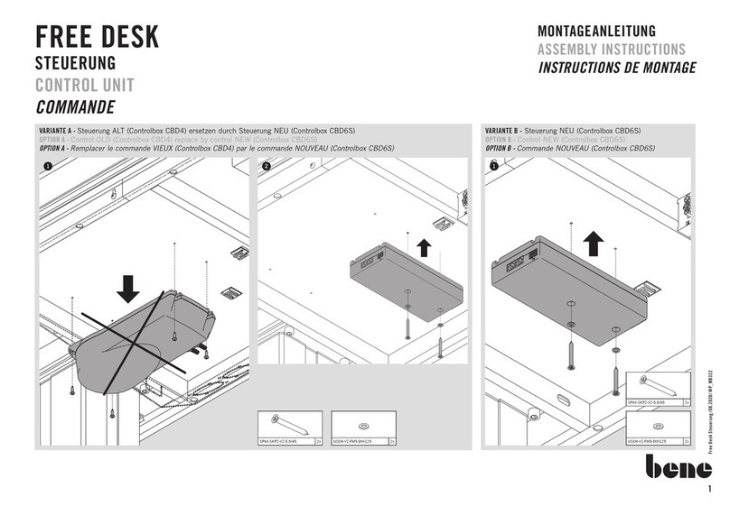
EN Terminal Clamp AKL-8-W
10.11.2021 RC-Junky English Conversion 4
Connection of LEDs and other components
The connection cables of the consumer/component/light can be connected to the
spring-loaded terminals of the AKL-8-W. To insert or remove a cable, just press from
above with a small screwdriver on the operating lever of the terminal. This opens the
clamp and the cable can be plugged in or out.
The cables should be stripped approx. 7 - 8 mm and be tinned with solder. The cable
cross-section can be between 0.14 mm² and 1.0 mm².
The switching outputs of BEIER-modules are negative switching, i.e. the negative lead
of the consumer is always connected to the outputs 1-8 of the terminal clamp.
The positive lead of the consumer to output 9 or 10 of the terminal clamp.
The switched voltage at the eight outputs is always as high as the module supply
voltage! Therefore, it is important to have the correct in series resistors inserted
in the base of the AKL-8-W (see below)!
The required value of the series resistor depends on 3 different factors:
•Level of the supply voltage (UB)
•Voltage of the LED (UL). Added together when connecting several LEDs in series
the individual stresses.
•Current of the LED (I)
The series resistance value (R) can be calculated using the following formula:
UB- UL
R = ---------- UL= (UL1 + UL2 + UL3 + ULn )
I
Example:
We have a supply voltage of 7.2 V and want a white LED with a supply voltage
3.4 V and 12 mA (= 0.012 A).
7.2 V - 3.4 V
R = ----------------- = 317 Ohms
0.012 A
However, since there is no resistance value of 317 Ohms available, we take the
closest available value of 330 Ohms.
Then the necessary power (P) of the resistor should also be checked:
P = (UB- UL) x I
P = (7.2 V - 3.4 V) x 0.012 A = 0.046 W
