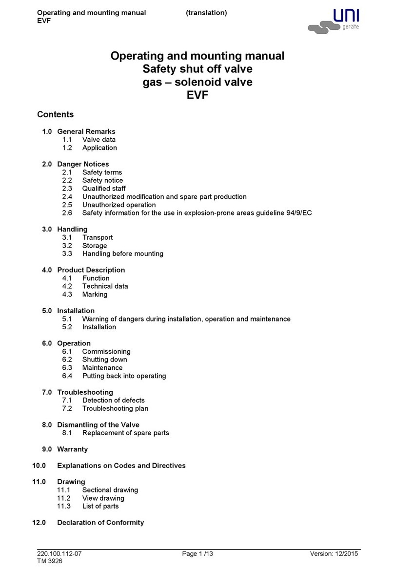
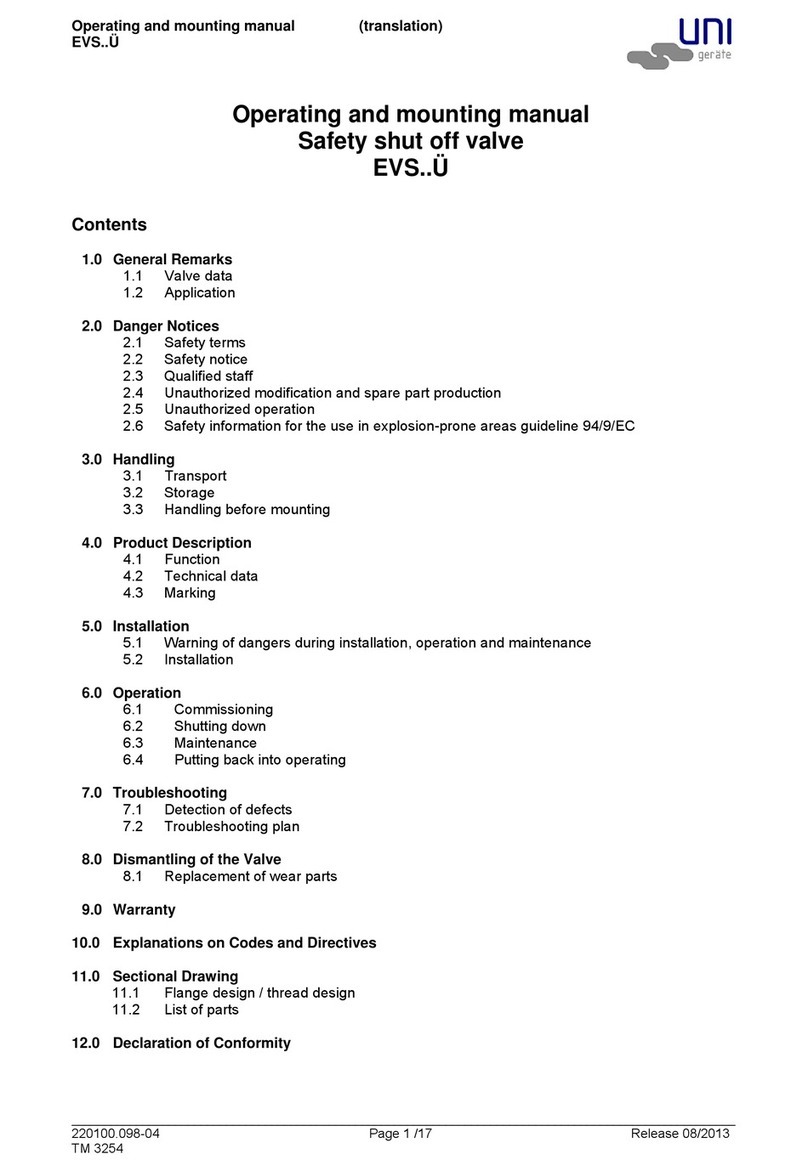
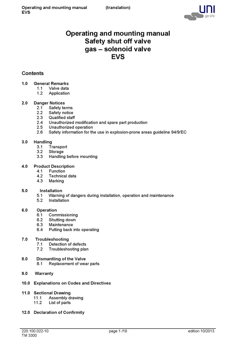
UNI Geräte EVSA Manual

EVSA
UNI Geräte E. Mangelmann
Elektrotechnische Fabrik GmbH
Holtumsweg 13
D-47652 Weeze, Germany
Telephone: +49 (0) 2837/9134-0
Fax: +49 (0) 2837/1444
Email: [email protected]
Homepage: www.uni-geraete.de
Automatic shut-off valve, solenoid valve (NC)
Operating and maintenance instructions

Explanation of symbols
2 221.100.002-00 03/2021
www.uni-geraete.com
Read instructions carefully before use. The operating instructions must always be available at the system’s
place of use.
Table of contents
1 Explanation of symbols 2
2Safety 3
2.1 General safety 3
2.2 Safety during operation in potentially explosive atmospheres 3
2.3 Other applicable information 4
3 Intended readers 4
4 Scope of delivery 4
5 Intended use 4
6 Technical specifications 5
6.1 Dimensions with standard solenoid drive 5
6.2 Assignment of solenoid drive types MG... 8
7 Technical description 9
7.1 Function 9
7.2 Identification 9
8 Transport 9
9Storage 10
10 Installation 10
10.1 Notes on installation 10
10.2 Installing the valve 11
10.3 Connecting the valve electrically 11
11 Commissioning 11
12 Decommissioning 11
13 Maintenance 12
13.1 Maintenance intervals 12
13.2 Maintenance at the plant operator 12
13.3 Maintenance at the manufacturer 13
13.4 Installing the spare parts kit 13
14 Disassembly 15
15 Troubleshooting 15
15.1 Troubleshooting chart 15
16 Disposal 16
17 Parts list 16
1 Explanation of symbols
Danger
Danger to life
• This symbol in conjunction with the signal word “Danger” indicates a hazardous situation that will lead to
death or serious injury.
Warning
Serious injuries!
• This symbol in conjunction with the signal word “Warning” indicates a hazardous situation that can lead to
death or serious injury.
Caution
Slight to moderate injuries!
• This symbol in conjunction with the signal word “Caution” indicates a hazardous situation that can lead to
minor or moderate injury.

Safety
03/2021 221.100.002-00 3
www.uni-geraete.com
Attention
Material damage!
• Indicates a situation that can lead to damage to property and the environment.
Note
Supplementary information on operating the product.
2 Safety
The manufacturer accepts no liability for damage in the following cases:
• Assembly or connection errors
• Damage to the product due to mechanical influences and incorrect connection voltage
• Modifications to the product without the express permission of the manufacturer
• Use for purposes other than those described in the manual
• Welding on load-bearing parts
• Operating the valve without safety devices
• Attaching fittings, components and devices that are not part of the scope of delivery and are not approved
by the manufacturer
2.1 General safety
• Before carrying out any work on the valve, de-energise the device and secure it against being switched on
again.
• Before working on the valve, depressurise the piping system.
• If the valve or its paintwork shows visible signs of damage, it must not be put into operation.
• Maintenance and repair work may only be carried out by personnel trained by the manufacturer who are
familiar with the hazards involved and the relevant regulations.
• Leakages of hazardous media (e.g. explosive, toxic, hot) must be discharged in such a way that they do
not pose a risk to persons or the environment.
2.2 Safety during operation in potentially explosive atmospheres
• The temperature of the medium must not exceed the maximum temperature of the corresponding temper-
ature class, or the respective maximum permissible medium temperature (See “Technical specifications”
on page 5).
• If the valve is heated, the temperature classes specified in the system must be observed.
• The valve must be earthed. In the simplest case, this can be implemented via the pipe screws by means
of toothed lock washers. Otherwise, earthing must be ensured by other measures, e.g. cable bridges.
• Control valves, electric and electric/mechanical actuators, and sensors must be subjected to their own
conformity assessment in accordance with ATEX. Special attention must be paid to the corresponding
safety and explosion protection instructions in the relevant operating instructions.
• The product is not subject to directive 2014/34/EU, since no effective ignition source occurs under the
loads that occur in practice, even in the event of a likely fault. This also applies to spring-loaded compo-
nents in the medium-conveying space. In the case of electric actuators, sensors or other electric compo-
nents, use must be checked separately in accordance with 2014/34/EU.
• Repainting the valve can lead to electrostatic charging processes, which would pose an ignition hazard.
Subsequent painting voids the ATEX approval with immediate effect.
• Any modification to the valve is prohibited. Unauthorised modifications to the valve will invalidate the ATEX
approval with immediate effect.
• Modifications are only permissible after consultation with the manufacturer.
Note
Safety verification with regard to Directive 2014/68/EU Annex I
UNI valves must not be used or classified as equipment with a safety function as defined by the Pressure
Equipment Directive 2014/68/EU Article 2 (4)( and Article 4 (1) (d) according to Category IV!

Intended readers
4 221.100.002-00 03/2021
www.uni-geraete.com
2.3 Other applicable information
3 Intended readers
These operating instructions contain the essential information and instructions for installing and maintaining
the valve. They are intended for skilled workers in installation companies who are familiar with the applicable
guidelines and safety precautions when installing pipe systems. Only personnel trained by the manufacturer
may carry out maintenance work.
4 Scope of delivery
Note
Immediately after receipt, check that the goods are complete and free of defects. Report any damage to the
valve or packaging to the shipping company immediately.
• Automatic shut-off valve with mounted solenoid drive
• Optional attachments
• Operating instructions for automatic shut-off valve
• Operating instructions for solenoid drive
• Operating instructions for optional attachments
5 Intended use
The EVSA solenoid valves are used as automatic shut-off valves for securing, limiting, shutting off and
releasing the gas and air supply at main shut-offs or upstream of gas burners.
The valves are suitable for the following gases:
• Gases corresponding to gas families according to DIN EN 437
• Gases of the 1st, 2nd and 3rd gas family according to G260
• Aggressive gases such as biogas, sewage gas or landfill gas according to G262 (only as variant with cor-
responding material design)
If the valve is to be used with operating data other than the intended data, check carefully whether the design
of the valve, accessories and materials is suitable for the new application. The system planner is responsible
for the valve’s area of application.
Operating instructions Document number
MG... series; MG..Xn series 220.100.038
MG...X series 220.100.040
MG...Xme series 220.100.039
Data sheet for overall fitting lengths DIN / ANSI 225.100.026

Technical specifications
03/2021 221.100.002-00 5
www.uni-geraete.com
6 Technical specifications
Further information on the electrical data can be found on the nameplate and in the operating instructions for
the specific solenoid drive.
6.1 Dimensions with standard solenoid drive
Threaded connection according to DIN ISO 228-1
4-EVSA 10-EVSA 16-EVSA 25-EVSA 40-EVSA
Valve class A
Group 2
Operating pressure 0 – 400 kPA
0 – 4 bar
0 –
1000 kPA
0 – 10 bar
0 –
1600 kPA
0 – 16 bar
0 –
2500 kPA
0 – 25 bar
0 –
4000 kPA
0 – 40 bar
Medium temperature
- Standard
- Optional
-20 °C to +60 °C
See nameplate
Ambient temperature -20 °C to +60°C
Supply voltage
- Direct current
- Alternating current
12 V – 440 V (–15% to +10%)
24 V – 500 V (–15% to +10%) (40–60 Hz)
Power consumption 10 – 4000 W
Degree of protection IP54 or IP65
Opening times 0.3 s – 0.7 s
Closing times < 1 s
Switching cycles see operating instructions for solenoid drive
Installation position (see name-
plate)
Vertical actuator:
Horizontal actuator:
Connection G Dime
nsion
1/4* 3/8 1/2 3/4 1 1 1/4 1 1/2 2
Overall length A 60 80 80 95 105 120 150 170
4/10-EVSA B 190 220 220 220 260 290 345 380
B` 240 305 305 310 370 400 495 525
ØC 83 106 106 106 127 127 153 153
D22.5 22.5 22.5 21 30 40 50 50
40-EVSA B --210-----
B` --330-----
ØC --127-----
D--22.5-----
*G1/4 only in 4-EVSA version

Technical specifications
6 221.100.002-00 03/2021
www.uni-geraete.com
Flange connection acc. to DIN EN 1092-2 / ANSI
DN flanges Dimen-
sion
15 20 25 32 40 50
Overall length A 130 150 160 180 200 230
ANSI flanges Dimen-
sion
1/2” 3/4” 1” 11/4” 11/2” 2”
4-EVSA B 240 240 290 320 370 375
B` 320 320 385 425 500 520
ØC 106 106 127 127 153 153
D50 50 55 68 68 75
10-EVSA B 290 290 290 320 370 375
B` 385 385 385 425 500 520
ØC 127 127 127 127 153 153
D50 50 55 68 68 75
16-EVSA B - - 460 - 480 -
B` - - 620 - 640 -
ØC - - 194 - 194 -
D--55-68-
25-EVSA B -----450
B` -----610
ØC -----194
D-----75
40-EVSA B 460 - 469 - - -
B` 620 - 620 - - -
ØC 194 - 194 - - -
D50-----
A = overall length acc. to DIN (e.g. ANSI flanges and DIN overall length or DIN flanges and overall length)
Overall length according to ANSI (see data sheet for overall fitting lengths DIN / ANSI 225.100.026 on our
homepage)
B` = dimension for removal of the solenoid drive
For solenoid drives for Ex-protection zone 1, the dimensions B and ØC change.
Observe dimensions for actuators with attached control system. (see operating instructions for solenoid
drive)

Technical specifications
03/2021 221.100.002-00 7
www.uni-geraete.com
DN flanges Dimen-
sion
65 80 100 125 150
Overall length A 290 310 350 400 480
ANSI flanges Dimen-
sion
21/2” 3” 4” - 6”
4-EVSA B 430 440 470 510 550
B` 590 600 630 670 710
ØC 194 194 194 194 194
D90 110 143 151 167
10-EVSA B 430 440 470 510 550
B` 590 600 630 670 710
ØC 194 194 194 194 194
D90 110 143 151 167
16-EVSA B - 440 - - -
B` - 600 - - -
ØC - 194 - - -
D- 110 - - -
25-EVSA B -----
B` -----
ØC -----
D-----
40-EVSA B 470 - - - -
B` 630 - - - -
ØC 194 - - - -
D90 - - - -
A = overall length acc. to DIN (e.g. ANSI flanges and DIN overall length or DIN flanges and overall length)
Overall length according to ANSI (see data sheet for overall fitting lengths DIN / ANSI 225.100.026 on our
homepage)
B` = dimension for removal of the solenoid drive
For solenoid drives for Ex-protection zone 1, the dimensions B and ØC change.
Observe dimensions for actuators with attached control system. (see operating instructions for solenoid
drive)

Technical specifications
8 221.100.002-00 03/2021
www.uni-geraete.com
6.2 Assignment of solenoid drive types MG...
(*) Test pressure for checking the external tightness. This check is not a functional test.
Actuator types with “A” consist of pick-up and holding coil.
Type test CE-0085AR0256 for all valves except:
Acceptance test certificate 3.2 possible
– not available
Maximum valve load due to pipeline forces
The specified torques must not be applied for longer than 10 s.
1) Not applicable for valves with flanges
Connection
G
1/4
(2)
3/8
(3)
1/2
(5)
3/4
(7)
1
(10)
1 1/4
(12)
1 1/2
(15)
2
(20)
Test pres-
sure (*)
PT
4-EVSA 005-3 008-2 008-2 008-2 010 012 014 016 PT10
10-EVSA – 008-2 008-2 008-2 010A5 012A5 014A5 016A5 PT16
40-EVSA ––012–––––PT40
DN flange
ANSI flange
PN 15
(5N)
1/2”
20
(7N)
3/4”
25
(10N)
1”
32
(12N)
1 1/4”
40
(15N)
1 1/2”
50
(20N)
2”
Test pres-
sure (*)
PT
4-EVSA 16 008-2 008-2 010 012 014 016 PT10
10-EVSA 16 010 010 010 012A5 014A5 016A5 PT16
16-EVSA 16 – – 018 – 018 – PT25
25-EVSA 40 – – – – – 019A5 PT40
40-EVSA 40 018 – 018 – – – PT40
DN flange
ANSI flange
PN 65
(25N)
2 1/2”
80
(30N)
3”
100
4”
125
-
150
6”
Test pres-
sure (*)
PT
4-EVSA 16 018 019A5 018A1 018A1 019A2 PT10
10-EVSA 16 019A5 018A1 018A1 019A1 019A2 PT16
16-EVSA 16 – 018A1 – – – PT25
25-EVSA 40 – – – – – PT40
40-EVSA 40 019A3.1 – – – – PT40
DN 8101520253240 50 65 80 100125≥150
Torsion1) Nm 20 35 50 85 125 160 200 250 325 400 – – –
Bending Nm 35 70 105 225 340 475 610 1100 1600 2400 5000 6000 7600

Technical description
03/2021 221.100.002-00 9
www.uni-geraete.com
7 Technical description
The EVSA solenoid valve is a direct-operated, normally closed (NC), quick-closing automatic shut-off valve
with solenoid drive.
The valve has a service life of 20 years.
7.1 Function
The following item numbers refer to the respective valve in Fig.1–Fig.7.
When the solenoid drive (800) is switched on, the solenoid core (207) is pulled against the Upper part of
housing (106). The pressure spring (503) is further preloaded and the actuator releases the valve cross-sec-
tion. The valve is open.
The valve closes by interrupting the energy supply to the solenoid drive. The pressure spring (503) is
preloaded and the actuator closes. The valve is closed at 15% of the nominal voltage.
7.2 Identification
The nameplate on the valve contains the following information:
• Manufacturer
• Valve type, nominal size, pressure and temperature specifications, installation position
• Year of manufacture / serial no.
• Valve class and group
• CE mark and number of the notified body
• Fluid group and PT test pressure
• Solenoid drive type
• Electrical power
• Voltage
• Frequency
• Degree of protection
• For solenoid drives for Ex-protection zone 1 additionally:
• Ignition protection type
• Certificates
8 Transport
Warning
Risk of crushing and impact during lifting and transport!
Due to the weight of the valve there is an increased risk of injury during transport.
• Have valve transported by trained personnel only.
• Wear sturdy boots and safety gloves during transport.
• Only use approved lifting tackle.
• Only use lifting equipment with a minimum load capacity greater than the weight of the component to be
lifted.
• Only lift the valve from the housing or the intended transport lugs, ring nuts or below the solenoid drive.
Never lift the valve by the cable connections, attachments or the device plug.
• Always keep a safe distance away from raised components.
• Never step under suspended loads.
• Never place the valve on attachments.
Attention
Material damage due to improper transport.
The valve may be damaged by mechanical influences during transport.
• Protect the valve against shock, impact or vibration during transport.
Material damage due to incorrect ambient temperature.
If the ambient temperature is too high or too low, the valve may warp or the paint may be damaged.
• Only transport the valve at ambient temperatures between -20 and +60 °C.

Storage
10 221.100.002-00 03/2021
www.uni-geraete.com
1. Attach protective caps to the sides of the valve.
2. Secure the device with lifting tackle. When doing so, only attach the lifting tackle to the housing. If possible,
transport the valve in a box or on a pallet with a soft underlay.
3. Place valve on level ground.
9 Storage
Store the valve and spare parts under the following conditions:
• Ambient temperature from -20 to +60 °C
• Max. humidity 40%
• Clean storage location
• Protect against sunlight
10 Installation
10.1 Notes on installation
Warning
Risk of crushing due to moving actuators!
Reaching into the device can lead to fatal injury from crushed and severed limbs.
• If the access point to the pipe system is less than 850 mm away from the valve or if the pipe is more than
500 mm in diameter, a safety guard must be installed.
• Protect the valve from the effects of weather, e.g. moisture.
• Before installation, compare the following valve specifications with the system diagram of the piping sys-
tem:
•Material
• Pressure
• Temperature
• Voltage
• Direction of flow
• Only connect and operate the valve when it is correctly installed.
See the nameplate for the valve’s installation position.
The valve must not be used as a fixed point. The valve is supported by the piping system.
For automatic shut-off valves: Install a strainer upstream of the valve. Observe the direction of flow
( in Fig. 1 – Fig. 7). The screen of the strainer must have the following characteristics:
• Clear mesh size ≤1.5 mm
• A test mandrel of Ø1 mm must not be able to pass through it.
When two valves are assembled in combination, one strainer is sufficient upstream of the first valve. UNI-
Geräte strainers of the SFR series in combination with solenoid valves are approved for use according to
EU/2016/426.
Tightening torques
Greased pipe screws
Greased product bolts and nuts
DN 8 101520253240506580 100 125≥150
Torque Nm 20 30 30 30 30 50 50 50 50 50 80 160 160
Bolt M6 M8 M10 M12 M16 M20 M24
Torque Nm 5 11 22 39 70 110 150

Commissioning
03/2021 221.100.002-00 11
www.uni-geraete.com
10.2 Installing the valve
Attention
If there is tension, the actuators may jam.
If the actuators jam, it may no longer be possible to reposition them.
• During installation, make sure that the valve is fitted in the pipeline without any strain.
• Compensate for thermal expansion of the pipeline with expansion joints.
1. Suspend the valve separately and align it as required. Observe the direction of flow (see markings on the
valve and in Fig. 1 – Fig. 7).
2. Protect valves from dirt.
3. Remove the protective caps.
4. Check the inside of the valve and the pipeline and, if necessary, clean them to remove any foreign parti-
cles.
5. Centre the seals between the connecting flanges. The connecting flanges must be aligned.
6. Tighten the flange screw connections. Observe the tightening torques (See “Tightening torques” on
page 10).
10.3 Connecting the valve electrically
Warning
Risk of crushing due to moving actuators!
Reaching into the device can lead to fatal injury from crushed and severed limbs.
• Only connect and operate the valve when it is correctly installed.
Danger of electric shock!
Live conductors pose a hazard when working on the valve.
• Before working on the valve, de-energise the electrical control line and secure it against being switched
on again.
1. Connect the valve to the electrical control system as described in the manufacturer’s documentation (See
“Other applicable information” on page 4).
11 Commissioning
Warning
Risk of fatal injury due to leaking piping system and missing protective devices!
Operating an incorrectly or incompletely installed piping system can lead to life-threatening injuries due to
escaping media.
• Ensure that all work on the piping system has been completed.
• Ensure that all protective devices are intact and correctly fitted.
• Ensure that the piping system is free of contamination.
1. Perform a leakage test.
12 Decommissioning
1. Depressurise the piping system.
2. Allow the medium in the piping system to cool down.
3. Drain the system.
4. Ventilate the piping system if media with one of the following properties are used:
• Corrosive
• Flammable
• Aggressive
•Toxic
5. Switch off the solenoid drive (800).

Maintenance
12 221.100.002-00 03/2021
www.uni-geraete.com
13 Maintenance
Warning
Danger to life due to improperly maintained valves!
If the valves are maintained at intervals that are too long or by untrained personnel, this can lead to life-
threatening injuries from escaping media.
• Observe the maintenance intervals specified in the maintenance schedule.
• Maintenance should only be carried out by personnel trained by the manufacturer.
Note
For dates and prices of manufacturer training courses, please contact the sales department (see cover sheet).
13.1 Maintenance intervals
Solenoid valves must be checked at regular intervals for function and internal leak tightness.
The intervals for regular checks must be determined by the operator according to the operating conditions.
Uni-Geräte prescribes the following maintenance intervals:
•Annually:
External visual inspection, as well as function test and internal and external leakage test (See “External
visual inspection” on page 12).
•Every five years (only for valves for which spare parts kits are available):
Internal visual inspection with replacement of all sealing elements. Then perform a functional test and an
internal and external leakage test (See “Internal visual inspection with replacement of all sealing ele-
ments” on page 12).
•Every ten years or at the latest after the following number of switching cycles:
Complete revision of the valve by the manufacturer (See “Maintenance at the manufacturer” on page 13).
13.2 Maintenance at the plant operator
External visual inspection
1. Check the valve and the paint for obvious damage and corrosion.
2. Check the valve for internal leaks.
3. Check the valve for external leaks.
4. Subject the valve to a functional test.
5. In the event of damage or reduced function: Replace the complete valve. Contact the manufacturer.
Internal visual inspection with replacement of all sealing elements
Note
An internal visual inspection is only required for models for which spare parts kits are available.
1. Remove the valve from the system (See “Disassembly” on page 15).
2. Disassemble the valve:
• Flange version 4/10-EVSA...; 16-EVSA 30N(H)..: (Page 14)
• Flange version 16/25-EVSA: (Page 14)
• Threaded version 4/10-EVSA 10 – 20 (1” – 2”): (Page 14)
3. Check the following items (see Fig. 1 – Fig. 7):
• Damage to the valve seat (100)
• Damage to the valve disc seal (400)
• Damage due to corrosion
• Wear on the guide rings (206)
Operating temperature DN ≤ 25 ≤ DN 80 ≤ DN 150 > DN 150
≤ 25°C 150,000 75,000 25,000 20,000
> 25°C 50,000 25,000 25,000 5,000

Maintenance
03/2021 221.100.002-00 13
www.uni-geraete.com
4. If there is damage to the valve seat: Replace the complete valve.
5. If there is wear on the guide rings: Replace guide rings.
6. If there is damage to the sealing elements:
• Flange version 4/10-EVSA...; 16-EVSA 30N(H)..: Install the spare parts kit (Page 13)
• Flange version 16/25-EVSA: Install the spare parts kit (Page 13)
• Threaded version 4/10-EVSA 10 – 20 (1” – 2”): Install the spare parts kit (Page 13)
7. Check the valve for internal leaks.
8. Check the valve for external leaks.
9. Subject the valve to a functional test.
10. Install the valve in the system (See “Installation” on page 10).
13.3 Maintenance at the manufacturer
If repair or maintenance work is to be carried out at the manufacturer’s site, take the following steps before
delivery:
1. Clean any substances harmful to health or the environment from the valves.
2. Complete the decontamination declaration and enclose it with the valve.
13.4 Installing the spare parts kit
Danger
Risk of explosion due to incorrect lubricants and sealing materials!
The medium may undergo a chemical reaction and explode if unsuitable lubricants or sealing materials are
used.
• For specific applications such as oxygen, use only approved lubricants and suitable sealing materials
(BAM approval, see also accompanying document 225.100.259).
Attention
Material damage due to contaminated surface.
Dirty surfaces can damage parts of the valve.
• Place all parts on a clean surface after disassembling them.
Note
Replace all the spare parts contained in the spare parts kit.
Spare parts
Version Fig. Type Spare part
Flange version
Fig. 1
4-EVSA 5N(H) – 150(H)
10-EVSA 5N(H) – 150(H)
16-EVSA 30N(H)
Spare parts kit, solenoid drive (800)
Fig. 2 16-EVSA 10N(H)/15N(H)
25-EVSA 20N(H) Spare parts kit, solenoid drive (800)
Flange version Fig. 3 40-EVSA 5NH Solenoid drive (800)
Fig. 4 40-EVSA 10NH Solenoid drive (800)
Fig. 5 40-EVSA 25NH Solenoid drive (800)
Threaded ver-
sion
Fig. 6 4-EVSA 2 - 7 Solenoid drive (800)
Fig. 6 10-EVSA 3 - 7 Solenoid drive (800)
Fig. 6 4/10-EVSA 10 - 20 Spare parts kit, solenoid drive (800)
Fig. 7 40-EVSA 5 Solenoid drive (800)

Maintenance
14 221.100.002-00 03/2021
www.uni-geraete.com
Install the spare parts kit for flange version 4/10-EVSA...; 16-EVSA 30N(H)..: Fig. 1
Disassembling the valve
1. Loosen the hexagon head screws (900/1).
2. Remove the housing flange (108).
3. Remove the Upper part of housing (106) completely.
4. Remove the spring bolt (210/1) and the pressure spring (503/1).
5. Remove the bolt (902/1) with the SL-retainer (949) or split pin (912).
6. Remove the solenoid core (207).
7. Remove the balance piston (220/1) with the piston guide (221/1) from the valve chamber (100).
8. Pull the balance piston (220/1) out of the piston guide (221/1).
Replacing wearing parts
1. Replace the O-rings (403/1, 403/2).
2. Replace the lip-rings (404/1, 404/3).
3. Replace the guide rings (206).
Installing the valve
1. Push the balance piston (220/1) into the piston guide (221/1).
2. Slide the balance piston (220/1) with the piston guide (221/1) into the valve chamber (100).
3. Secure the solenoid core (207) with the bolt (902/1) and the SL-retainer (949) or split pin (912).
4. Insert the pressure spring (503/1) and the spring bolt (210/1).
5. Fit the Upper part of housing (106).
6. Mount the housing flange (108).
7. Tighten the hexagon head screws (900/1) (See “Tightening torques” on page 10).
Install the spare parts kit for flange version 16/25-EVSA: Fig. 2
Disassembling the valve
1. Loosen the setscrew (941/1).
2. Completely unscrew the Upper part of housing (106).
3. Remove the spring bolts (210/1) and the pressure springs (503/1).
4. Remove the bolt (902/1) with the SL-retainer (949) or split pin (912).
5. Remove the solenoid core (207).
6. Loosen the hexagon head screws (900/1).
7. Disassemble the housing flange (108) with housing cylinder (109).
8. Remove the balance piston (220/1) with the piston guide (221/1) from the valve chamber (100).
9. Pull the balance piston (220/1) out of the piston guide (221/1).
Replacing wearing parts
1. Replace the O-rings (403/1, 403/2, 403/3).
2. Replace the lip-rings (404/1, 404/3).
3. Replace the guide rings (206).
Installing the valve
1. Push the balance piston (220/1) into the piston guide (221/1).
2. Slide the balance piston (220/1) with the piston guide (221/1) into the valve chamber (100).
3. Install the housing flange (108) with housing cylinder (109).
4. Tighten the hexagon head screws (900/1) (See “Tightening torques” on page 10).
5. Secure the solenoid core (207) with the bolt (902/1) and the SL-retainer (949) or split pin (912).
6. Insert the pressure springs (503/1) and spring bolts (210/1).
7. Screw on the Upper part of housing (106).
8. Tighten the setscrew (941/1).
Install the spare parts kit for threaded version 4/10-EVSA 10 – 20 (1” – 2”): Fig. 6
Disassembling the valve
1. Completely unscrew the Upper part of housing (106).
2. Remove the spring bolt (210) and the pressure spring (503).
3. Remove the bolt (902) with the SL-retainer (949) or split pin (912).
4. Remove the solenoid core (207).
5. Unscrew the balance piston (220/1) with the piston guide (221/1) from the valve chamber (100).
6. Pull the balance piston (220/1) out of the piston guide (221/1).

Disassembly
03/2021 221.100.002-00 15
www.uni-geraete.com
Replacing wearing parts
1. Replace the O-rings (403/1, 403/2).
2. Replace the lip-rings (404/1, 404/3).
3. Replace the guide rings (206).
Installing the valve
1. Push the balance piston (220/1) into the piston guide (221/1).
2. Screw the balance piston (220/1) with the piston guide (221/1) into the valve chamber (100).
3. Secure the solenoid core (207) with the bolt (902) and the SL-retainer (949) or split pin (912).
4. Insert the pressure spring (503) and spring bolt (210).
5. Screw on the Upper part of housing (106).
14 Disassembly
Warning
Danger of burns from hot components.
The solenoid drive can become hot during continuous operation. This poses a risk of burns.
• Allow the solenoid drive to cool down or wear suitable gloves before disassembling it.
1. Depressurise the piping system.
2. Allow the medium in the piping system to cool down.
3. Drain the system.
4. Ventilate the piping system if media with one of the following properties are used:
• Corrosive
• Flammable
• Aggressive
•Toxic
5. Disconnect the valve from the power supply and secure it against being switched on again.
6. Secure the valve against falling down.
7. Loosen the flange screw connections.
8. If the valve is to be serviced: Insert protective caps.
9. Dismantle the solenoid drive (see operating instructions for solenoid drive).
15 Troubleshooting
1. In the event of a malfunction, first check whether the valve has been mounted correctly.
2. If the valve has been mounted correctly, use the troubleshooting chart.
3. If the problem persists, contact the manufacturer.
15.1 Troubleshooting chart
The following item numbers refer to the respective valve in Fig.1–Fig.7.
Fault Possible causes Remedy
No flow Valve does not open Switch on solenoid drive (800)
Check voltage
Operating pressure too high Compare operating pressure with data
on nameplate
Protective caps have not been removed Remove the protective caps
Low flow rate Dirty strainer Clean/replace strainer
Blockage in piping system Check piping system
Valve leaking at the
seat, no internal tight-
ness
Valve disc seal (400) or valve seat (100)
damaged by foreign objects
Replace seals (See “Installing the spare
parts kit” on page 13) or valve

Disposal
16 221.100.002-00 03/2021
www.uni-geraete.com
16 Disposal
1. Dismantle valve completely and dispose of in individual parts.
17 Parts list
Legend:
= direction of flow
= spare parts kit
X = optional limit switch mounting
(...#) = only with back pressure
(...x) = supplied as a complete unit
No external tightness Seals damaged Replace seals (See “Installing the spare
parts kit” on page 13) or valve
Valve does not close Voltage too high Check whether residual voltage is pres-
ent (See “Function” on page 9)
Flange break
(valve/pipeline)
Screws tightened on one side Align pipeline, install new valve
Counter-flanges are not aligned
Item Qty. Designation Description
100 1 Ventilgehäuse Valve chamber
106 1 Oberteil Upper part of housing
108 1 Gehäuseflansch Housing flange
109 1 Gehäusezylinder Housing cylinder
110 1 Distanzstück Spacer
205 1 Ventilspindel Valve spindle
206 2 Führungsring Guide ring
207 1 Magnetkern Solenoid core
210/1 1/3 Federbolzen Spring bolt
210/2 1 Federbolzen Spring bolt
213 1 Gewindering Threaded ring
214 1 Ventilstift Valve pin
215 1 Tellerscheibe Plate screw
218 1 Zweiteiliger Ring Two-piece ring
220 1 Ausgleichskolben Balance piston
220/2 1 Ausgleichskolben Balance piston
221/1 1 Kolbenführung Piston guide
221/2 1 Kolbenführung Piston guide
246 1 Verbindungsstück Endschalter Connection piece limit switch
400 1 Ventiltellerdichtung Valve disc seal
Fault Possible causes Remedy

Parts list
03/2021 221.100.002-00 17
www.uni-geraete.com
Quantities of the individual components may vary depending on the version.
403/1 1 O-Ring O-ring
403/2 1 O-Ring O-ring
403/3 1 O-Ring O-ring
404/1 1/2 Lippenring Lip-ring
404/2 1 Lippenring Lip-ring
404/3 1 Lippenring (nur bei Gegendruck) Lip-ring (only with back pressure)
405 1 Abstreifring Scraper ring
503/1 1/3 Druckfeder Pressure spring
503/2 1 Druckfeder Pressure spring
800 1 Magnetantrieb Solenoid drive
900/1 4/6/8/12 Sechskantschraube Hex. head screw
900/2 4 Sechskantschraube Hex. head screw
901 1 Sechskantmutter Hex. nut
902/1 1 Bolzen Bolt
902/2 1 Bolzen Bolt
903 1 Kerbstift Grooved dowel pin
905 4/6/8/12 Federring Lock washer
908 1 Sicherungsblech Locking plate
912 1 Splint Split pin
941/1 1 Gewindestift Setscrew
941/2 1 Gewindestift Setscrew
948/1 4/6 Nordlockscheibe Nordlock washer
948/2 4 Nordlockscheibe Nordlock washer
949 1 SL-Sicherung SL-retainer
965 1 Filtersieb Filter sieve
966/1 1 DU-Buchse DU-bush
966/2 1 DU-Buchse DU-bush
978 1 Stoßdämpfer ACE Shock absorber ACE
Item Qty. Designation Description

18 221.100.002-00 03/2021
www.uni-geraete.com
4/10-EVSA
16-EVSA 30N(H)
1

03/2021 221.100.002-00 19
www.uni-geraete.com
16/25-EVSA
2

20 221.100.002-00 03/2021
www.uni-geraete.com
40-EVSA 5NH..
3
This manual suits for next models
29
Table of contents
Other UNI Geräte Control Unit manuals
Popular Control Unit manuals by other brands

Mitsubishi Electric
Mitsubishi Electric MELSEC-QS Series user manual

Yoshitake
Yoshitake GD-28S-NE product manual

Murphy
Murphy M2582 Series Installation and operation instructions

BVA Hydraulics
BVA Hydraulics PW2 instruction manual

NI
NI TBX-68 user guide

Pfeiffer Vacuum
Pfeiffer Vacuum UHV 016 CU operating instructions

Ara-Unicontrol
Ara-Unicontrol UNICONTROL user manual

Akron Brass
Akron Brass Style 8840 Instructions and parts list

Applied Biosystems
Applied Biosystems GeneAmp PCR System 9700 user manual

ARI
ARI ELIPTIX R-30 Series Installation operation & maintenance

Kuppersbusch
Kuppersbusch ESW 307.6 manual

Itho Daalderop
Itho Daalderop I2C manual