Premio MX100H Series User manual

USER’S
MANUAL
MX100H Series
Monitor Module

MX100H lUser’s Manual
Table of Contents
Prefaces …………………………………………………….……………………………………………. 03
Revision …………………………………………………………………………………………..……………….……….. 03
Disclaimer ………………………………………………………..…….…….………………………….……………….. 03
Copyright Notice …………………………………….…………………….…………………………………………… 03
Trademarks Acknowledgment …………..………………………………………………………...................03
Environmental Protection Announcement …………………………….………………….……………….. 03
Safety Precautions ………………………………………….……………………………….…………….………….. 04
Technical Support and Assistance …………………………………….…………….…………….…………….05
Conventions Used in this Manual ………………………………………………………………….….………..05
Package Contents …………………………………………………………………………………………….…………06
Ordering Information …………………………………….……………………………………….……….………… 06
Optional Accessory …………...……………………………………..................................................... 06
Chapter 1 Product Introductions ………………………………………………………..… 07
1.1 Overview ……………………….………………………………..………….…………………………..08
1.1.1 Key Feature ………….……………………………………….……….…..…………….......08
1.2 Hardware Specification ….………………………….....…………….…………..………………09
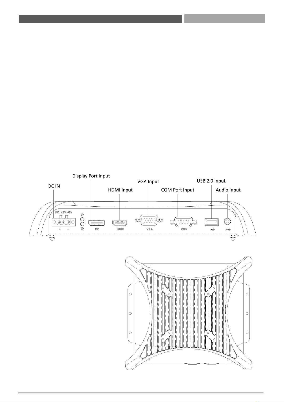
1.3 System I/O ……………………………..……………………..…………………………………………10
1.3.1 Rear ………………….………..……….......................…………………………………… 10
1.3.2 Top ……………………………………………………...……………..……….………………... 10
1.4 Mechanical Dimension …………………………..…………………………..………….………. 11
Chapter 2Switches and Connectors ……………………………………………………. 12
2.1 Switch and Connector Locations ……………………………………..…….…………….... 13
2.1.1 Top View ………………………………………………………………………..……………… 13
2.1.2 Bottom View ………………………………………………………………………..………..13
2.1.3 Rear I/O ………………………………………………………………………..…………..….. 13
2.2 Connector / Switch Definition ……………………………….……….…….………............ 14
2.3 I/O Interface Descriptions …………................................................................ 15
Chapter 3 Front Panel Controls …………………………..………………………………… 22
3.1 Users Controls ……...………………………………………………………………..………..……...23
3.1.1 Power Button ………………………….……………………………………..………………23
3.1.2 LED ……………………………………………………………..………………………..……….. 23
3.1.3 MENU / Enter Button ……………….………………………………………………..…. 23
3.1.4 Increase Button …………………………..……………………………………………..…. 23
3.1.5 Decrease Button ……………….………………………………………………………..….23
3.1.6 AUTO / Exit Button ……………………………………………………………………..….23
3.2 OSD Operation ……………………………….…..…….………………………….……………….… 24
3.2.1 Luminance ……………………………………………………………….………………..…. 24
3.2.2 Picture ……………………………………………………………………..………………..…. 25
3.2.3 Color …………………………………………………………………………..……………..…. 25
3.2.4 OSD Settings …………………………………………………….………………………..…. 25
3.2.5 Setup ……………………………………………………………………..…………………..….26
Chapter 4System Setup ……………………..………………………………………………… 27
4.1 Connecting with VIO Series Display Module ……...……………………..……..……... 28
2

MX100H lUser’s Manual
3
Revision
Disclaimer
All specifications and information in this User’s Manual are believed to be accurate and up to date. Premio
Inc. does not guarantee that the contents herein are complete, true, accurate or non-misleading. The
information in this document is subject to change without notice and does not represent a commitment on
the part of Premio Inc.
Premio Inc. disclaims all warranties, express or implied, including, without limitation, those of
merchantability, fitness for a particular purpose with respect to contents of this User’s Manual. Users must
take full responsibility for the application of the product.
Copyright Notice
All rights reserved. No part of this manual may be reproduced or transmitted in any form or by any means,
electronic or mechanical, including photocopying, recording, or information storage and retrieval systems,
without the prior written permission of Premio Inc. Copyright © Premio Inc.
Trademarks Acknowledgment
Intel®, Celeron® and Pentium® are trademarks of Intel Corporation.
Windows® is registered trademark of Microsoft Corporation.
AMI is trademark of American Megatrend Inc.
IBM, XT, AT, PS/2 and Personal System/2 are trademarks of International Business Machines Corporation
All other products and trademarks mentioned in this manual are trademarks of their respective owners.
Environmental Protection Announcement
Do not dispose this electronic device into the trash while discarding. Please recycle to minimize pollution
and ensure environment protection.
Prefaces
Revision Description Date
1.0 Manual Released 2021/06/30
Preface

MX100H lUser’s Manual
4
Safety Precautions
Before installing and using the equipment, please read the following precautions:
Put this equipment on a reliable surface during installation. Dropping it or letting it fall could
cause damage.
The power outlet shall be installed near the equipment and shall be easily accessible.
Turn off the system power and disconnect the power cord from its source before making any
installation. Be sure both the system and the external devices are turned OFF. Sudden surge
of power could ruin sensitive components. Make sure the equipment is properly grounded.
When the power is connected, never open the equipment. The equipment should be opened
only by qualified service personnel.
Make sure the voltage of the power source is correct before connecting the equipment to the
power outlet.
Disconnect this equipment from the power before cleaning. Use a damp cloth. Do not use
liquid or spray detergents for cleaning.
Avoid the dusty, humidity and temperature extremes.
Do not place heavy objects on the equipment.
If the equipment is not used for long time, disconnect it from the power to avoid being
damaged by transient over-voltage.
The storage temperature shall be above -20°C and below 70°C.
The computer is provided with a battery-powered real-time clock circuit. There is a danger of
explosion if incorrectly replaced. Replace only with the same or equivalent type
recommended by the manufacturer.
If one of the following situation arises, get the equipment checked be service personnel:
•The power cord or plug is damaged.
•Liquid has penetrated into the equipment.
•The equipment has been exposed to moisture.
•The equipment does not work well or it cannot work according the user’s manual.
•The equipment has been dropped and damaged.
•The equipment has obvious signs of breakage.
Preface

MX100H lUser’s Manual
5
Technical Support and Assistance
1. Visit the Premio Inc website at https://premioinc.com/where you can find the latest information
about the product.
2. Contact your distributor, our technical support team or sales representative for technical support if
you need additional assistance. Please have following information ready before you call:
Model name and serial number
Description of your peripheral attachments
Description of your software (operating system, version, application software, etc.)
A complete description of the problem
The exact wording of any error messages
Conventions Used in this Manual
Preface
This indication alerts operators to an operation that, if not strictly observed,
may result in severe injury.
WARNING
This indication alerts operators to an operation that, if not strictly observed,
may result in safety hazards to personnel or damage to equipment.
CAUTION
This indication provides additional information to complete a task easily.
NOTE

MX100H lUser’s Manual
6
Package Contents
Before installation, please ensure all the items listed in the following table are included in the package.
Preface
Note: Notify your sales representative if any of the above items are missing or damaged.
Item Description Q’ty
1MX100H Seris Monitor Module 1
2USB Cable 1
3VGA Cable 1
4Screw Pack 1
Ordering Information
Model No. Product Description
MX100H Monitor Module with 1x VGA Input, 1x HDMI Input, 1x DP Input, 1x USB
2.0 Input
Optional Accessories
Model No. Product Description
1-E09A06007 Adapter AC/DC 12V 5A 60W with 3pin Terminal Block Plug 5.0mm Pitch
SFICBL022 Power Cord, 3-pin US Type, 180cm
1-TPCD00002 Power Cord, European Type, 180cm
1-TPCD00001 Power Cord, 3-pin UK Type, 180cm

Chapter 1
Product Introductions

MX100H lUser’s Manual
8
1.1 Overview
The MX100H series monitor module featuring with flat surface, IP 65 dust/waterproof front panel, and
aluminum die-casting front frame with rugged body structure, it is rugged and reliable for industrial
environment. By supporting Multi-Mode Display Module (MDM) technology, enabling MX100H series
monitor module to configure, upgrade and maintain easily.
The MX100H series supports both digital and analog signal input via three types of display interface:
VGA, HDMI and DisplayPort. Touch screen can be connected with USB or COM port. It also has multi-
language OSD function for adjusting the view options of display. In addition, supporting wide range
power input from 9 to 48VDC and high reliability even operating in temperature extremes, MX100H is
designed as an ideal solution for industrial application.
Featuring with completely cable-less designed and high functional, MX100H series are ruggedized
display systems that can operate in harsh environments and easy to install and maintain. A build in
over voltage protection (OVP), over current protection (OCP), reserve protection, and wide range DC
power input makes MX100H series are safety system for all industrial applications.
Chapter 1: Product Introductions
1.1.1 Key Features
1x VGA, 1x DisplayPort, 1x HDMI
1x USB 2.0, 1x COM, 1x Audio
9 to 48VDC wide range power input
-10°C to 60°C extended operating temperature

MX100H lUser’s Manual
9
1.2 Hardware Specification
Chapter 1: Product Introductions
I/O
•1x VGA Input
•1x HDMI Input
•1x DisplayPort Input
•1x Audio Input
•1x USB 2.0 Input
•1x COM Port Input (Resistive Touch Only) (USB
& COM port are reserved for the connection to
enable touch usage only)
Power
•1x 3-pin Terminal Block Connector with Power
Input 9~48VDC
•Power Ignition Sensing
•1x Optional AC/DC 12V/5A, 60W Power
Adapter
•Power Protection
OVP (Over Voltage Protection)
OCP (Over Current Protection)
Reserve Protection
Environment
•Operating Temperature: Ambient with Air Flow:
-10°C to 60°C (with Industrial Grade Peripherals)
•Storage Temperature: -20°C to 70°C
•Relative humidity: 10%~95% (non-condensing)
Physical
•Dimension: 246 (W) x 220 (D) x 37 (H) mm
•Weight: 1.61kg
•Construction: Extruded Aluminum with Heavy
Duty Metal
•Mounting: VESA Mounting Holes 75 x 75mm,
100 x 100mm
Certifications
•CE
•FCC Class A

MX100H lUser’s Manual
10
Chapter 1: Product Introductions
1.3 System I/O
1.3.1 Rear
DC IN
Used to plug a DC power input
with terminal block.
HDMI
Used to connect a DisplayPort monitor
VGA
Use the rear panel standard 15-pin female VGA
connector to connect the monitor to the system
graphics interface.
DisplayPort
The DisplayPort connector connects to a display
device with DisplayPort interface.
COM Port for Touch Panel Connector (Resistive
Touch Only)
Use the rear panel female DB-9 touch panel
connector to connect the monitor to the system
interface.
USB for Touch Panel Connector
Use the rear panel standard USB touch panel
connector to connect the monitor to the system
interface.
Audio-in
This port connects PC audio source by the bundled
audio cable.
1.3.2 Top
VESA Mounting Hole
These are mounting holes for VESA
mount (75x75mm and 100x100mm)

MX100H lUser’s Manual
11
Chapter 1: Product Introductions
1.4 Mechanical Dimensions
Unit: mm

Chapter 2
Switches and Connectors

MX100H lUser’s Manual
13
Chapter 2: Switches and Connectors
2.1 Switch and Connector Locations
2.1.1 Top View
2.1.2 Bottom View
DC_IN1 DP_IN1 HDMI1 VGA_IN1 COM_IN1
USB_IN1
AUDIO_IN1
SIG_OUT1
2.1.3 Rear I/O

MX100H lUser’s Manual
14
Chapter 2: Switches and Connectors
2.2 Connector / Switch Definition
List of Connector / Switch
Connector Location Definition
DC_IN1 3-pin DC 9~48V Power Input Connector
DP_IN1DisplayPort Input Connector
HDMI HDMI signal connector
VGA_IN1 VGA Input Connector
COM_IN1 COM Port Input Connector
USB_IN1USB 2.0 Input Connector
AUDIO_IN1Audio Input Connector
SIG_OUT1VIO Display Module Connector

MX100H lUser’s Manual
Chapter 2: Switches and Connectors
2.3 I/O Interface Descriptions
Chapter 2: Switches and Connectors
2.3.1 Power Connector
DC_IN1
Pin Signal
19_48VSB_IN
29_32VSB_ACC
3GND_VIN
31
DP_IN1
Pin Signal Pin Signal
1DP_RX3N 11 GND
2GND 12 DP_RX0P
3DP_RX3P 13 GND
4DP_RX2N 14 GND
5GND 15 DP_AUXP
6DP_RX2P 16 DP_DET
7DP_RX1N 17 DP_AUXN
8GND 18 DP_HPD
9DP_RX1P 19 GND
10 DP_RX0N 20 DP_3V3
2.3.2 DisplayPort Input
1
2
19
20
15

MX100H lUser’s Manual
Chapter 2: Switches and Connectors
2.3 I/O Interface Descriptions
Chapter 2: Switches and Connectors
2.3.3 HDMI signal connector
HDMI1
Pin Signal Pin Signal
1HDMI_RX32+ 11 HDMI_DET
2GND 12 HDMI_RX3C-
3HDMI_RX32-13 NC
4HDMI_RX31+ 14 NC
5GND 15 HDMI_SCL
6HDMI_RX31-16 HDMI_SDA
7HDMI_RX30+ 17 GND
8GND 18 HDMI_5V
9HDMI_RX3C+ 19 HDMI_HPD
10 HDMI_RX3C+ 20
1
19
2
18
16

MX100H lUser’s Manual
Chapter 2: Switches and Connectors
2.3 I/O Interface Descriptions
Chapter 2: Switches and Connectors
2.3.4 VGA Input
VGA_IN1
Pin Signal Pin Signal
1RED+ 9GND
2GREEN+ 10 NC
3BLUE+ 11 DDC_SDA_VGA
4NC 12 HSYNC
5VGA_DET 13 VSYNC
6RED- 14 DDC_SCL_VGA
7GREEN- 15 GND
8BLUE-
1
5
11
15
17

MX100H lUser’s Manual
Chapter 2: Switches and Connectors
2.3 I/O Interface Descriptions
Chapter 2: Switches and Connectors
18
2.3.5 COM Port Input
COM_IN1
Pin Signal
1NC
2RX_R_2
3NC
4TX_R_2
5NC
6NC
7NC
8NC
5
1
9
6
2.3.6 USB 2.0 Input Connector
USB_IN1
Pin Signal
1NC
2USBN_2
3USBP_2
4GND
14

MX100H lUser’s Manual
Chapter 2: Switches and Connectors
2.3 I/O Interface Descriptions
Chapter 2: Switches and Connectors
19
2.3.7 Audio Input
AUDIO_IN1
Pin Signal
1AGND2
2AIN_R
3AGND2
4AGND2
5AIN_L

MX100H lUser’s Manual
Chapter 2: Switches and Connectors
2.3 I/O Interface Descriptions
Chapter 2: Switches and Connectors
20
2.3.8 VIO Display Module Connector
SIG_OUT1
100
1
2
99
Pin Signal Pin Signal
1RXO0+ 2DDC_SDA_VGA
3RXO0- 4 DDC_SCL_VGA
5GND 6GND
7RXO1+ 8EDID_0
9RXO1-10 EDID_1
11 GND 12 GND
13 RXO2+ 14 EDID_2
15 RXO2-16 EDID_3
17 GND 18 GND
19 RXO3+ 20 HDMI_SDA
21 RXO3-22 HDMI_SCL
23 GND 24 GND
25 RXOC+ 26 USBP
27 RXOC-28 USBN
29 GND 30 GND
31 RXE0+ 32 TX_R
33 RXE0-34 RX_R
35 GND 36 GND
Table of contents
Popular Control Unit manuals by other brands

GSD
GSD B70R150 quick start guide

tams elektronik
tams elektronik KSM-4 manual

Hach
Hach 2100Q User instructions

Grundfos
Grundfos CIM 260 Installation and operating instructions

System Sensor
System Sensor SC-6 Installation and maintenance instructions

Tucker-Davis Technologies
Tucker-Davis Technologies TDT PA5 Hardware reference