3
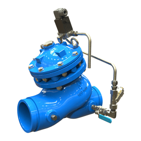
400E-Y Deluge Valve
Table No.1: Pressure Ratings
Table No.2: 400E-Y Flow Ratings
Valves sizes 3” 4” 6” 8” 10”
CV (Kv) 190 (219) 345 (398) 790 (912) 1160 ( 1340) 1430 ( 1652)
Leq m (ft), see Note 1 8 (25) 8 (26) 13 (43) 27 (89) 55 (179)
Max. Flow-Rate m3/hr (GPM) 102 450) 159 (700) 363 (1600) 795 (3500) 1136 (5000)
Note 1: Valve Equivalent Length Value (Steel Pipe), for use in hydraulically calculated system
2. Installation
NOTES:
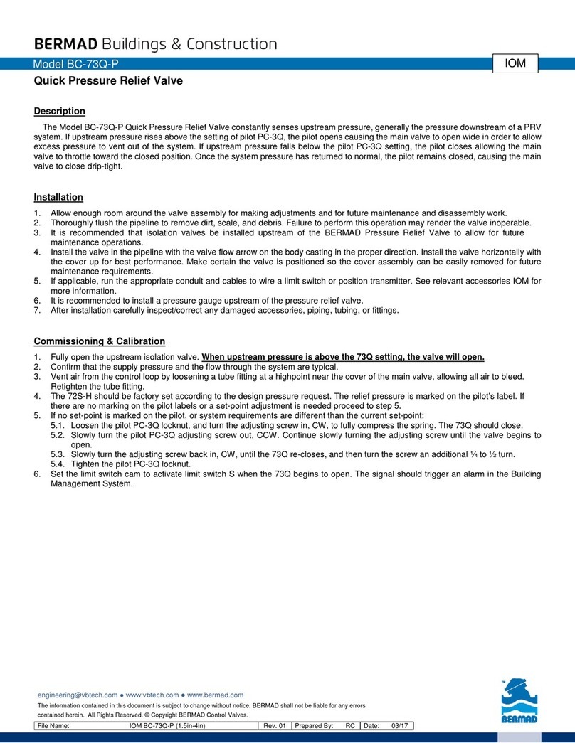
■Proper operation of the Bermad 400E-Y Deluge Valves depends upon their trim being installed.
■The 400E-Y valve shall be trimmed with specific trim components and accessories, it must be installed and
maintained in compliance with the most recent Bermad publications.
■Any deviation in trim size or arrangement may adversely affect the proper operation of the deluge valve.
Warning: The deluge valve and trim must be installed only in areas where they will not be subject to freezing.
2.1 Installation Instructions
1. Allow enough room around the valve assembly for any adjustments and future maintenance.
2. Before the valve is installed, flush the pipeline to remove any dirt, scale, debris, etc.
Warning: not flushing the line may result in the valve being rendered inoperable.
3. Install the valve on the pipeline with valve flow arrow designated on the body points in the desired direction.
4. Install a listed / approved indicating valve upstream of the system (supervised “open”).
5. All other components are positioned correctly as per the appropriate drawing.
6. The water supply priming line must be connected to the upstream of the system control valve.
7. For Hydraulic or Pneumatic trim: Install an "End of Line Release Valve" with maximum bore of 1/2", installed
at the same level or higher than the highest fusible plug position and located at the remotest location on the
system possible.
8. For pneumatic / Electro-Pneumatic trim: Install a pneumatic pressure supply system, see “Pneumatic System
Pressure Requirements" below.
9. Pneumatic System Pressure Requirements: see "Placing in Service" section below prior to any air supply
connection.
10. A Solenoid Valve shall be wired to the Releasing Control Panel according to information provided by the
panel manufacturer.
11. All additional accessories, although not packed together with the BERMAD Deluge Valve, must be installed
as shown in the relevant drawing and other illustrations.
12. After installation in the main line, carefully inspect/correct any damaged accessories, piping, tubing, or fittings;
ensure that there are no leaks.
Valve End
Connections Standard Rating/ Class
Max Working Pressure
barg psig
Flanged ANSI B16.5 / 16.42 #150 17.4 250
Flanged ANSI B16.5 / 16.42 #300 25 365
Flanged ISO 7005-2 PN16 16 235
Flanged ISO 7005-2 PN25 25 365
Grooved ANSI / AWWA C606 365 25 365


