BEKA BA384NG User manual

Issue: 6
9th July 2019
BA384NG
Ex nA and Ex tc
Two input
Rate Totaliser
Issue 6

2
1. DESCRIPTION
2. OPERATION
2.1 Initialisation
2.2 Controls
2.3 Displays
2.3.1 Display over-range
3. CERTIFICATION
3.1 ATEX Ex nA certification
3.2 Zones, gas groups & T rating
3.3 Safety parameters
3.4 Special conditions for safe use
3.5 Power supply
3.6 Pulse input terminals
3.7 Remote reset terminals
3.8 Pulse output
3.9 Certification label information
4. SYSTEM DESIGN FOR HAZARDOUS AREAS
4.1 Power supply
4.2 Pulse inputs
4.2.1 Switch contact input
4.2.2 Open collector input
4.2.3 2-wire proximity detector input
4.2.4 Magnetic pick-off input
4.2.5 Voltage pulse input
4.3 Remote reset
5. INSTALLATION
5.1 Location
5.2 Installation procedure
5.3 EMC
5.4 Units of measurement and tag marking on
scale card.
6. CONFIGURATION AND CALIBRATION
6.1 Calibration structure
6.2 Accessing configuration functions
6.3 Summary of configuration functions
6.4 Rate totaliser function: function
6.5 Input: input
6.6 Input type: inp.type
6.7 Debounce: debounce
6.8 Display update interval: update
6.9 Composite display: count
6.10 Upper display: di5p-1
6.11 Lower display: di5p-2
6.12 Position of decimal points: dp
6.13 Flowmeter K-factor: factor-a
6.14 Total scale factor: 5cale.t-a
6.15 Rate scale factor: 5cale.r-a
6.16 Timebase: t-ba5e
6.17 Display filter: filter-a
6.18 Clip-off: clp.off-a
6.19 Local reset: loc clr
6.20 Local total reset: clt tot
6.21 Local grand total reset: clr gtot
6.22 External reset: e clr
6.23 Grand total reset from configuration menu:
clr-gtot
6.24 Define security code: code
6.25 Reset to factory defaults: r5et def
7. LINEARISERS
7.1 Flowmeter specification
7.2 Summary of lineariser configuration
functions.
7.3 Copy A lineariser to b lineariser: copy a2b
7.4 Add a segment: add
7.5 Remove a segment: del
7.6 Input frequency: pul5e fr
7.7 Flowmeter K-factors: l-factor
7.8 Lineariser error messages
7.9 Lineariser factory defaults
8. Pulse Output
8.1 Configuration
8.2 Access pulse output sub-menu
8.3 Enable pulse output: enbl
8.4 Source of output pulse: 5ource
8.5 Divide output pulse frequency: divide
8.6 Define output pulse width: duration
8.7 Stored pulses
CONTENTS
The BA384NG is CE marked to show compliance with European Explosive Atmospheres Directive 2014/34/
EU and European EMC Directive 2014/30/EU.

3
9. CONFIGURATION EXAMPLE
9.1 Configuration procedure
10. MAINTENANCE
10.1 Fault finding during commissioning
10.2 Fault finding after commissioning
10.3 Servicing
10.4 Routine maintenance
10.5 Guarantee
10.6 Customer comments
11. ACCESSORIES
11.1 Units of measurement and instrument
identification.
11.2 Legend plate
11.3 Backlight
11.4 Alarms
11.4.1 Solid state output
11.4.2 Ex nA certification
11.4.3 Configuration & adjustment
11.4.4 Alarm enable: enbl
11.4.5 Type of alarm: type
11.4.6 Setpoint adjustment: 5p1r-a
11.4.7 Alarm function: hi:lo
11.4.8 Alarm output status: no:nc
11.4.9 Hysteresis: h5tr
11.4.10 Alarm delay: dela
11.4.11 Alarm silence time: 5il
11.4.12 Flash display: fl5h
11.4.13 Access setpoints: ac5p
11.4.14 Adjusting alarm setpoints
from totalising mode.
11.5 4/20mA output
11.5.1 Ex nA certification
11.5.2 Configuration
11.5.3 Access 4/20mA output sub-menu:
4-20 op
11.5.4 Enable 4/20mA output: enbl
11.5.5 Select rate or total source:
4-20type
11.5.6 Display which corresponds to
4mA output: 4.000
11.5.7 Display which corresponds to
20mA output: 20.000
Appendix 1 ATEX dust certification
Appendix 2 IECEx certification
Appendix 3 ETL and cETL certification for
installation in USA and Canada.

4

5
1. DESCRIPTION
The BA384NG is an Ex nA and Ex tc certified, field
mounting rate totaliser with two pulse inputs,
primarily intended for use with two flowmeters in
Zones 2 or 22.
The BA384NG simultaneously displays the rate of
flow and the total flow in the same or different
engineering units. Either input, or their sum or
difference may be shown. The BA384NG is
controlled and configured via the four front panel
push buttons, a user defined four digit code may be
entered to prevent accidental access to the
instrument's configuration menu.
The BA384NG has been issued with a Type
Examination Certificate ITS16ATEX48409X by
Notified Body Intertek Testing and Certification Ltd.
This confirms compliance with the type of protection
requirements for non-sparking Ex nA apparatus, and
for dust ignition protection by enclosure Ex tc. This
certificate has been used to confirm compliance with
the European ATEX Directive 2014/34/EU.
The main sections of this manual describe ATEX
Ex nA gas certification. Ex tc dust certification is
described in Appendix 1.
For international applications the BA384NG also has
IECEx certification which is described in Appendix 2.
For applications in the USA and Canada the
BA384NG has ETL & cETL certification which is
described in Appendix 3.
This instruction manual supplements the
abbreviated instruction sheet supplied with each
instrument.
2. OPERATION
Fig 1 shows a simplified block diagram of the
BA384NG Rate Totaliser. The instrument has two
separate inputs 'A' and 'b' which can accept pulses
from two flowmeters and display the individual rates
and totals, or the sum or difference of the two rates
and totals.
Each input may be individually configured to accept
pulses from a wide variety of flowmeter sensors and
to display the rate of flow and the total flow in the
same or different engineering units.
When the flowmeter sensors requires energising to
determine their state, such as a switch contact, open
collector or a two wire proximity detector, an external
link connected between BA384NG terminals
supplies power to the appropriate input.
Each Rate Totaliser channel has a separate
lineariser with up to sixteen straight-line segments
that may be configured to compensate for flowmeter
non-linearity.
The BA384NG Rate Totaliser has an isolated pulse
output which may be configured to synchronously
retransmit either of the two pulse inputs, or a
scaleable pulse when the least significant digit of
total display is incremented.
The following factory fitted accessories are
available:
Internally powered display backlight
Dual isolated alarm outputs
Isolated 4/20mA current sink output
Fig 1 BA384NG Rate Totaliser block diagram

6
2.1 Initialisation
Each time power is applied to a BA384NG
initialisation is performed. After a short delay the
following display sequence occurs:
All segments of the display are activated
The Rate Totaliser starts functioning using
the configuration information stored in the
instrument's permanent memory. Unless
the total and grand total displays have been
reset to zero, any new flow will be added to
the existing totals.
2.2 Controls
The BA384NG is controlled and configured via four
front panel push buttons. In the totalising mode i.e.
when the instrument is displaying rate and total flow
the push button functions are:
Push Button Functions
& or *Scrolls both displays between:
Input A
Input b
Input A + b or Input A – b which
is configurable. See 6.9
)+&Grand total - shows the least
significant 8 digits of a 16 digit
counter.
)+*Grand total - shows the most
significant 8 digits of a 16 digit
counter. If buttons are pressed for
longer than 10 seconds the grand
total will be reset to zero if the
grand total reset function clr gtot
is enabled. See 6.21
To reset the grand total to zero from
the operating mode press the
) and+* buttons for ten seconds
until CLr.no is displayed. Using the
&or *button change the display
to Clr .YE5 and press ) which will
reset the grand total and restore the
original display.
&+*If the local total reset function
clr tot is enabled in the
configuration menu, simultaneously
pressing the &and *buttons for
more than three seconds allows
total A, total b or both totals to be
selected by operating the &or *
button. Operating the ) button
will then reset the selected total to
zero and clear any stored output
pulses. See 6.20
(+&Shows each for 2 seconds:
Firmware and version numbers
Function of instrument: 2chtotal
Options fitted:
-A Alarms
-C 4/20mA output
-P Pulse output (always fitted)
(+ *Provides direct access to the alarm
setpoints when the Rate Totaliser is
fitted with optional alarms and the
AC5P setpoints function has been
enabled.
(+)Access to the configuration menu

7
2.3 Displays
The BA384NG has two digital displays and
associated annunciators, plus a flow indicator as
shown on the front cover of this manual.
Total display Shows the total flow of the
selected input or the composite
flow A + b or A - b usually on the
upper eight digit display. May
be reset to zero by the front
panel push buttons or a remote
reset switch.
Rate display Shows the flow rate of the
selected input or the composite
flow rate A + b or A - b usually on
the lower six digit display.
Flow indicator This disc in the lower left hand
corner of the instrument display
'rotates' for two seconds each
time an input pulse is received
on the input being displayed.
Appears to rotate continuously
when input frequency exceeds
0.5Hz.
Hold Activated when input frequency
annunciator is below the clip-off threshold for
the input being displayed.
Reset Activated while the instrument is
annunciator being reset.
Rate Identifies the rate display
annunciator
Total Identifies the total display
Annunciator
RTx Retransmitted pulse
annunciator annunciator.
Depends upon the setting of
5ource in the pulse output
configuration menu.
5caled:
Annunciator activated each
time pulse output open
collector is on, i.e. Ron is
less than 60+ 3V.
direct:
Annunciator continuously
activated.
2.3.1 Display over-range
Over-range of the upper eight digit display or the
lower six digit display is indicated by all the digits
displaying 9and all the decimal points flashing.

8
3. CERTIFICATION
The BA384NG has ATEX, IECEx and ETL Ex nA gas
and Ex tc dust certification. The main sections of
this instruction manual describes ATEX Ex nA gas
certification. ATEX dust certification is described in
Appendix 1, IECEx gas and dust certification in
Appendix 2 and ETL certification in Appendix 3.
3.1 ATEX Ex nA certification
Notified Body Intertek Testing and Certification Ltd
have issued the BA384NG with a Type Examination
Certificate number ITS16ATEX48409X. This has
been used to confirm compliance with the European
ATEX Directive for Group II, Category 3G
equipment. The instrument carries the Community
Mark and, subject to local codes of practice, may be
installed in any of the European Economic Area
(EEA) member countries and in EFTA states,
Iceland, Liechtenstein and Norway. ATEX
certificates are also acceptable in Switzerland and
Turkey. The European Commission's Blue Guide
lists the member states, overseas countries and
territories that have adopted harmonisation
legislation.
This section of the instruction manual describes
ATEX installations in explosive gas atmospheres
conforming with EN 60079-14 Electrical installations
design, selection and erection. When designing
systems for installation outside the UK the local
Code of Practice should be consulted.
3.2 Zones, gas groups and T rating
The BA384NG Rate Totaliser has been certified as
Group II Category 3G Ex ic nA IIC T5 Gc
Ta -40ºC to +60°C apparatus. This is non-sparking
apparatus complying with EN 60079-15 Equipment
protection by type of protection 'n' that minimises the
risk of arcs or sparks capable of creating an ignition
hazard occurring during conditions of normal
operation.
The Rate Totaliser's front panel push button contacts
are non incendive and have been certified
intrinsically safe Ex ic without Zener barriers or
galvanic isolators as shown on the Type
Examination Certificate. This allows the Rate
Totaliser to be adjusted and configured live when
installed in Zones 2.
When connected to a suitable system the BA384NG
Rate Totaliser may be installed in:
Zone 2 explosive gas air mixture not
likely to occur, and if it does
will only exist for a short time.
Be used with gases in groups:
Group A propane
Group B ethylene
Group C hydrogen
In gases that may safely be used with equipment
having a temperature classification of:
T1 450oC
T2 300oC
T3 200oC
T4 135oC
T5 100oC
At ambient temperatures between -40 and +60oC.
This allows use with all commonly used industrial
gases except carbon disulphide CS2.
3.3 Safety parameters
The certificate specifies input safety parameters in
normal operation i.e. without faults for all the
instrument terminals. Where only a voltage or only
a current is specified, the unspecified parameter will
be defined by components within the BA384NG
Rate Totaliser.
3.4 Special conditions for safe use
The Ex nA certificate has an ‘X’ suffix indicating that
the certificate defines special conditions for safe
use. These state that the BA384NG Rate Totaliser
should be:
a. Supplied from a limited energy circuit with
output parameters in normal operation equal
to, or less than the instrument’s input
parameters. The certificate states that It is
not necessary to power the instrument from
an intrinsically safe interface, such as a
certified shunt diode safety barrier or a
galvanic isolator to comply with this
requirement.
b. Fitted with cable entry glands or conduit
fittings which maintain the impact and ingress
protection of the enclosure. Certified Ex e or
Ex n components satisfy these requirements.
The BA384NG is supplied fitted with one
certified M20 stopping plug and one
temporary hole plug which should be replaced
with the required gland or conduit fitting.

9
3.5 Power supply
The input safety parameters for the BA384NG Rate
Totaliser power supply terminals 1 and 2 are:
Ui = 30V dc
Ii = 100mA
This allows the BA384NG to be powered from any
dc supply which in normal operation has an output
of less 30V and 100mA. See section 4.1 for power
supply recommendations.
3.6 Pulse input terminals
The BA384NG Rate Totaliser has two pulse inputs, A
and b, that may be individually configured for use
with different types of flowmeter. Each input is a
separate Ex nA circuit, although the negative side of
each input is internally connected to the negative
side of the power supply and the reset terminal RS2.
See Fig 1. The two inputs should not be connected
in parallel.
For flowmeters with sensors that require energising
to determine their state, such as a switch contact,
open collector or a 2-wire proximity detector in a
turbine flowmeter, fitting an external link between
terminals 3 & 4 of the BA384NG for input A and
between terminals 7 & 8 for input b, connects an
internal 7V, 6mA supply to the respective input.
Energising is not required when a BA384NG input is
connected to a voltage pulse source.
Fitting an energising link changes the safety
parameters of each BA384NG input as shown in the
following table which also shows the types of
flowmeter sensor requiring energising (link fitting).
Safety parameters
Input Output
Type of input Link *Ui Uo Io
Switch contact Yes 15V 10.5V 9.2mA
Proximity detector Yes 15V 10.5V 9.2mA
Open collector Yes 15V 10.5V 9.2mA
Magnetic pick-off No 30V 1.1V 0.5mA
Voltage input (low) No 30V 1.1V 0.5mA
Voltage input (high) No 30V 1.1V 0.5mA
*For input A link terminals 3 and 4
*For input b link terminals 7 and 8
3.7 Remote reset terminals
The BA384NG total display may be reset by
connecting the external reset terminals RS1 and
RS2 together for more than one second. The two
reset terminals have the following safety parameters
in normal operation:
Ui = 30V
Uo = 3.8V
Io = 1mA
3.8 Pulse output
The BA384NG Rate Totaliser has an isolated pulse
output which may be configured to synchronously
retransmit either of the two pulse inputs, or a
scaleable pulse when the least significant digit of
total display is incremented.
The pulse output is a passive unpowered open
collector which is isolated from all other Rate
Totaliser circuits. The output has the following Ex nA
safety parameters:
Ui = 30V dc
Ii = 100mA
This allows the pulse output to be connected to any
dc circuit providing that in normal operation the
maximum supply voltage is not greater than 30V dc
and the current is not greater than 100mA.
3.9 Certification label information
The BA384NG Rate Totaliser certification
information label is fitted in a recess on the top outer
surface of the instrument enclosure. It shows the
ATEX, IECEx and ETL certification information plus
BEKA associates name, location, year of
manufacture and the instrument serial number.
BA384NG Certification information label

10
4. SYSTEM DESIGN FOR HAZARDOUS
AREAS.
When correctly installed in Zone 2 the BA384NG
Rate Totaliser may be connected to almost any
pulse output flowmeter in the safe area and to Ex n,
Ex e, Ex p and Ex d protected pulse output
flowmterers located in Zone 2. Because the
BA384NG is not certified intrinsically safe it should
not be connected to an intrinsically safe system.
BEKA Application Guide AG310, Guide for
Installation of [extra low voltage d.c.] Ex nA
instrumentation, which can be downloaded from
www.beka.co.uk, contains explanations and
recommendations for the installation of Ex nA
equipment.
In addition to being able to be connected to
flowmeters in the safe area and in Zone 2, the
BA384NG may also be connected to suitably
protected and certified flowmeters located in Zone 1.
This is explained in Application Guide AG310.
There are four design requirements:
1. The BA384NG should be powered from a
circuit that has output safety parameters in
normal operation equal to, or less than, the
input safety parameters for terminals 1 and 2
specified by the BA384NG ATEX Type
Examination Certificate.
2. BA384NG input, reset and output terminals
should only be connected to circuits having
safety parameters in normal operation
compliant with the BA384NG safety
parameters which are specified by the ATEX
Type Examination Certificate.
3. Hazardous area apparatus to which the
BA384NG is connected should be protected by
a technique suitable for the Zone in which the
equipment is located, such as Ex n or Ex e if
located in Zone 2. Equipment protected by
intrinsic safety should not be connected to a
BA384NG.
4. Wiring should comply with Clause 9 of
EN 60079-14.
When designing a system it is important to
remember that terminals 2, 6, 10 and RS2 are
interconnected within the BA384NG. See Fig 1.
4.1 Power supply
The BA384NG Rate Totaliser requires a minimum of
10V between terminal 1 & 2 and consumes:
10mA without optional backlight
plus 6mA when terminals 3 & 4 are linked
plus 6mA when terminals 7 & 8 are linked
plus 16mA with optional backlight
A 24V dc regulated, current limited supply located in
a safe area is suitable.
The power supply should meet the requirements for
personnel safety so that ‘live maintenance’ can
safely be performed. The implicit requirement for
galvanic isolation from the mains supply ensures
that the possible difficulties from circulating earth
currents caused by mains faults is minimised. In
European terms if the power supply is CE marked it
is almost certainly acceptable.
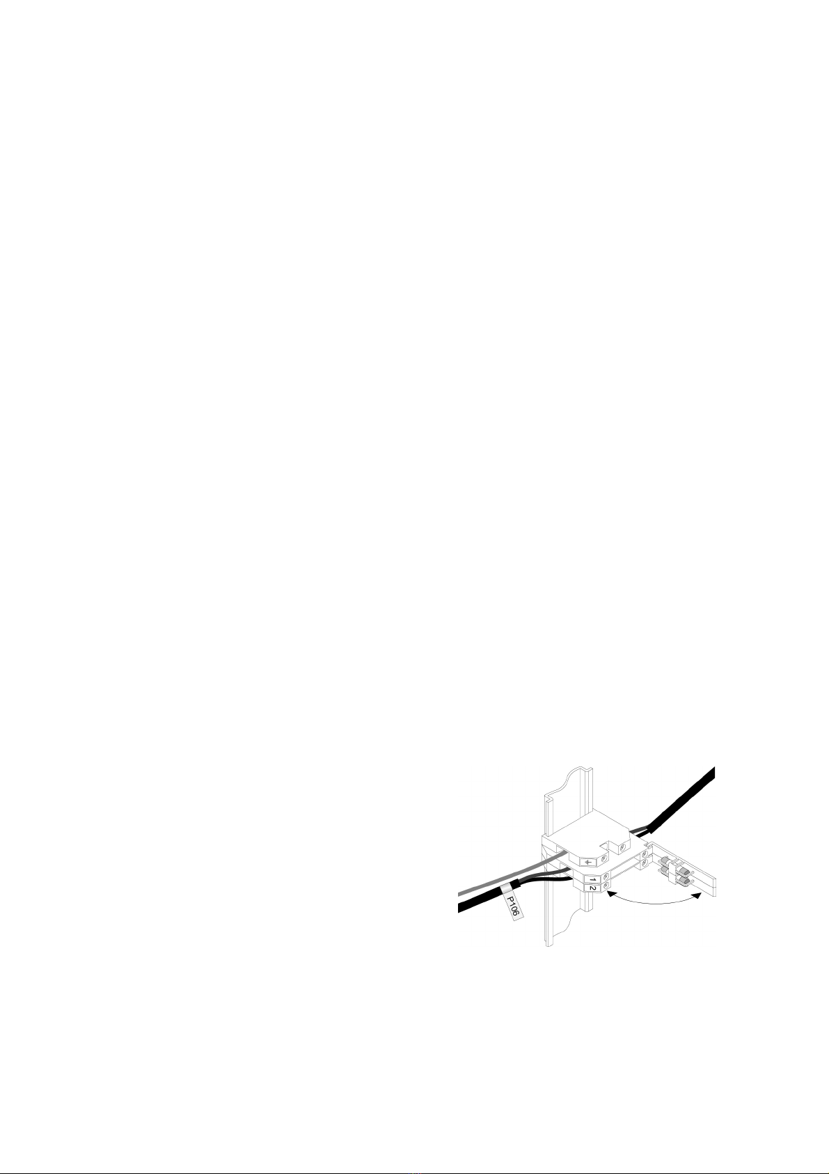
To comply with the requirements of EN 60079:14
Electrical installations design, selection and erection,
each of the wires entering the hazardous area
should be individually fused and contain a means of
isolation. These two requirements may be satisfied
by using DIN rail mounted terminals incorporating
easily removable fuses which can be extracted to
achieve isolation as shown in Fig 2.
If an input current safety parameter Ii is specified, a
suitably rated fuse will ensure that it is not
continuously exceeded in normal operation.
Clear identification of, and easy access to the
means of isolation is essential for their effective use.
It is also necessary to ensure that the maintenance
procedure makes sure that unauthorised re-closure
of the switches does not occur.
It is not considered necessary to have a means of
isolation or electrical protection for the screen.
Fig 2 DIN rail mounting terminals incorporating a
fuse.
For some applications Ex nA instrumentation
energised by a current limited power supply or
instrument that can be switched off, is considered
adequate and to comply with the requirements of the
standard.

11
4.2 Pulse inputs
As shown in Fig 3 both BA384NG Rate Totaliser
inputs may be connected to Zone 2 hazardous area
flowmeters with a wide variety of outputs, or to safe
area flowmeters as shown in Fig 4.
The following table shows the Rate Totaliser's input
switching thresholds when configured to operate
with various sensors. For reliable operation input
pulses must fall below the lower threshold and rise
above the upper threshold.
Flowmeter output Switching thresholds
Lower Upper
Switch contacts 1001000
Proximity detector 1.2mA 2.1mA
Open collector 2k10k
Magnetic pick-off 0mV 40mV peak
Voltage pulse low 1.0V 3.0V
Voltage pulse high 3.0V 10.0V
Flowmeters with a switch contact, proximity detector
or an open collector output require energising to
determine their state which is achieved by linking
two BA384NG terminals together for each input as
shown in Figs 3 and 4.
Fig 3 BA384NG flowmeters in Zone 2
The flowmeters may also be located in the safe area
as shown in Fig 4.
Fig 4 BA384NG flowmeters in the safe area.
4.2.1 Switch contact input
Any Zone 2 certified flowmeter, except intrinsically
safe instruments, with a mechanically or
magnetically activated switch contact output may be
directly connected to input terminals 5 & 6 or 9 &10.
The flowmeter should be located in the same
hazardous area as the BA384NG, and the flowmeter
and associated wiring should be able to withstand a
500V rms insulation test to earth. Most
magnetically activated reed relays used in turbine
flowmeters comply with these requirements. The
BA384NG contains a configurable debounce circuit
to prevent contact bounce being counted. Three
levels of debounce protection are independently
available for each input. See section 6.7.

12
4.2.2 Open collector input
Most Zone 2 certified flowmeters, except intrinsically
safe instruments, with an open collector output may
be directly connected to input terminals 5 & 6 or 9
&10. The flowmeter should be located in the same
Zone 2 hazardous area as the BA384NG, and the
flowmeter and associated wiring should be able to
withstand a 500V rms insulation test to earth.
The BA384NG contains a configurable debounce
circuit to prevent false triggering. Three levels of de-
bounce protection are independently available for
each input. See section 6.7.
4.2.3 2-wire proximity detector input
Most Zone 2 certified flowmeters, except intrinsically
safe instruments, incorporating a NAMUR 2-wire
proximity detector may be directly connected to a
BA384NG input, providing the operating voltage of
the flowmeter (proximity detector) is less than 7.5V.
The flowmeter should be located in the same
hazardous area as the BA384NG and with the
associated wiring be able to withstand a 500V rms
insulation test to earth.
The BA384NG contains a configurable de-bounce
circuit to prevent false triggering. Three levels of
debounce protection are independently available for
each input. See section 6.7.
4.2.4 Magnetic pick-off input
Flowmeters incorporating a magnetic pick-off to
sense flow will have a low level voltage output
unless the flowmeter incorporates an amplifier. CoiL
in the BA384NG input configuration menu is a low
level voltage pulse input which will sense this output.
Most Zone 2 certified flowmeters, except intrinsically
safe instruments, with a low level magnetic pick-off
output may be directly connected to input terminals
5 & 6 or 9 &10.
The flowmeter should be located in the same
hazardous area as the BA384NG and with the
associated wiring be able to withstand a 500V rms
insulation test to earth. The BA384NG contains a
configurable de-bounce circuit to prevent false
triggering. Three levels of debounce protection are
independently available for each input. See
section 6.7.
4.2.5 Voltage pulse input
Two voltage pulse input ranges are independently
selectable in the BA384NG Rate Totaliser
configuration menu, VoLt5 L and VoLt5 H. When
configured for either of the voltage pulse ranges, the
Rate Totaliser’s input terminals 5 & 6 and 9 & 10
may be directly connected to most certified Zone 2
certified flowmeters, except intrinsically safe
instruments, with a high level voltage pulse output.
The BA384NG contains a configurable debounce
circuit to prevent false triggering of the instrument.
Three levels of de-bounce protection are
independently available for each input,
See section 6.7.
4.3 Remote reset
The BA384NG Rate Totaliser's total display may be
remotely reset to zero by connecting terminals RS1
and RS2 together. Permanent interconnection
inhibits totalisation. Remote resetting may be
accomplished by any mechanically operated switch
located in Zone 2 as the Rate Totaliser's reset circuit
is non incendive. The reset switch and the
associated wiring should be able to withstand a
500V rms insulation test to earth.
A BA384NG may also be remotely reset from the
safe area. Any switch may be used. Fig 3 illustrates
how a BA384NG may be reset from both the safe
and the hazardous area.
The BA384NG total display may also be reset when
the &and *push buttons are operated
simultaneously in the totalising mode i.e. when the
instrument is displaying flow. See 6.19
4.4 Pulse output
The BA384NG Rate Totaliser has an opto-isolated
Ex nA certified open collector pulse output which can
be configured to synchronously retransmit either of
the two pulse inputs, or a scaleable pulse when the
least significant digit of total display is incremented.
The output has the following electrical parameters:
V max = 30V dc
Imax = 10mA
Ron = 60+ 3V
Roff = 1M
Providing the BA384NG Rate Totaliser is correctly
installed in Zone 2, the pulse output may be
connected to any dc circuit in Zone 2 or in the safe
area. In normal operation the maximum supply
voltage should not be greater than 30V dc and the
maximum current should not be greater than 10mA.

13
The retransmitted RTx annunciator on the
instrument display shows the status of the
retransmitted pulse output. Annunciator activation
depends upon the setting of 5ource in the pulse
output configuration menu.
5caled:
Annunciator activated each time pulse output
open collector is on, i.e. Ron is less than
60+ 3V.
direct:
Annunciator continuously activated
Fig 5 shows a BA384NG Rate Totaliser installed in
Zone 2 with the pulse output connected to a safe
area load. The pulse output flows through R1
resulting in a voltage output of about 20V in the safe
area when the pulse output is activated.
Fig 5 Retransmitting pulse output to safe area.

14
5. INSTALLATION
5.1 Location
The BA384NG Rate Totaliser is housed in robust
IP66 glass reinforced polyester (GRP) enclosure
incorporating an armoured glass window and
stainless steel fittings making it suitable for exterior
mounting in most industrial Zone 2 on-shore and
off-shore installations. The Rate Totaliser should be
positioned where the display is not in continuous
direct sunlight.
Field wiring terminals are located on the rear of the
Rate Totaliser assembly as shown in Fig 7.
To ensure electrical continuity between the two
conduit or cable entries, the enclosure back-box is
fitted with a bonding plate which includes an M4
earth stud. The bonding plate may be mounted on
the inside or outside of the enclosure. If the carbon
loaded GRP enclosure is not bolted to an earthed
post or structure, this earth stud should be
connected to a local earth or the plant potential
equalising conductor.
An insulated M4 stud is provided in the bottom right
hand corner of the back-box for interconnecting
cable screens.
The BA384NG Rate Totaliser may be pipe mounted
using a BA393G pipe mounting kit.
5.2 Installation Procedure
Fig 6 illustrates the instrument installation
procedure.
A. Remove the Rate Totaliser assembly by
unscrewing the four captive 'A' screws.
B. Mount the enclosure back-box on a flat surface
and secure with screws or bolts through the
four 'B' holes. Alternatively use a pipe
mounting kit which is available as an
accessories.
C. Remove the temporary hole plug and install an
appropriate IP and temperature rated certified
M20 x 1.5mm cable gland or conduit fitting. If
two entries are required, the supplied IP66
stopping plug should be replaced with an
appropriate IP and temperature rated certified
M20 x 1.5mm cable gland or conduit fitting.
D. Pass the field wiring through the cable entry in
the back-box and connect it to the instrument
terminals as shown in Fig 7. Replace the
instrument assembly on the back-box and
evenly tighten the four 'A' screws.
Fig 6 BA384NG installation procedure
Fig 7 Dimensions and terminal connections

15
5.3 EMC
The BA384NG complies with the requirements of the
European EMC Directive 2014/30/EU. For specified
immunity all wiring should be in screened twisted
pairs, with the screens earthed at one point in the
safe area.
5.4 Units of measurement and tag marking
on scale card.
The Rate Totaliser's units of measurement and tag
information are shown on a scale card which slides
into the instrument.
New Rate Totalisers are supplied with a printed
scale card showing the requested units of
measurement and tag information. If this information
is not supplied when the instrument is ordered, a
blank scale card will be fitted which can easily be
marked on-site with a dry transfer or a permanent
marker. Custom printed scale cards are available
from BEKA associates as an accessory.
To remove the scale card from a Rate Totaliser
carefully pull the transparent tab at the rear of the
instrument assembly away from the assembly as
shown in Fig 8a.
Fig 8a Removing scale card
To replace the scale card carefully insert it into the
slot on the right hand side of the input terminals as
shown in Fig 8b. Force should be applied evenly to
both sides of the scale card to prevent it twisting.
The card should be inserted until about 2mm of the
transparent tab remains protruding.
Fig 8b Inserting scale card into the
instrument assembly.

16
6.0 CONFIGURATION AND CALIBRATION
The BA384NG Rate Totaliser is configured and
calibrated via four front panel push buttons. Figs 9
and 10 show the configuration structure and the
menu.
Each menu function is summarised in section 6.3 of
this manual and each summary includes a reference
to more detailed information. The two sixteen
segment linearisers and the pulse output are
described separately in sections 7 and 8.
When factory fitted optional alarms and 4/20mA
outputs are included, additional functions appear in
the configuration menu which are described
separately in section 11.
All new BA384NG Rate Totalisers are supplied
calibrated as requested at the time of ordering. If
calibration is not requested, Rate Totalisers will have
default configuration which is shown in the following
table, but can easily be re-configured on-site.
Function Display Default
Access code CodE 0000
Function FunCtion 5td
A Input* inP .tYPE-A oP.CoL
Debounce dEbounCE dEFAuLt
Update uPdAtE 0 .5
Count Count A :b
Upper display di5p-1 totAL
Lower display di5P-2 5td
Decimal point dP Total00000000
Rate 0000.0
Factor input A* FACtor-A 001 .00
Total scale factor input A* 5cALE .T-A 001 .00
Rate scale factor input A* 5cALE .R-A 001 .00
Timebase t-bA5E tb-01(secs)
Filter for input A* FiLter-A 24
Clip-off for input A* CLP .oFF-A 0000.0
Local total reset Clr tot oFF
Local grand total reset Clr Gtot oFF
Pulse source 5ource 5caled
divide 1
duration 0 .1
External reset E clr clr anb
Access code CodE 0000
Notes:
1. Defaults for input A are shown. Functions
which are duplicated for input b are identified
with an *. The input b functions have the
same default as the input A function.
2. While the instrument is being configured
totalisation continues so that any flow
occurring during this time is recorded.
6.1 Calibration structure
Fig 9 shows the BA384NG calibration structure.
Two identical channels enable the rate and total
displays for input A and input b to be independently
configured.
Configuration functions which only apply to one Rate
Totalisier channel are identified with a suffix, i.e. the
rate scale factor 5CALE .r-A applies to channel A and
5CALE .R-b applies to channel b. Configuration
functions that do not have a channel suffix, such as
the timebase t-bA5E, apply to both channels.
The frequency of pulses received at each input is
divided by FACtor-A or FACtor-b, which is usually
set to the K-factor of the flowmeter, thus converting
the flowmeter output into engineering units. When
linearisation Lin is selected in the Function sub-
menu, up to 16 values for FACtor-A and FACtor-b
may be entered, each starting at a specified input
pulse frequency. Linearisation compensates for
flowmeter nonlinearity and increases totalisation
accuracy. See section 7.
5CALE-r is a dividing factor that converts the output
from FACtor into the required engineering units for
the rate display. e.g. if the output from FACtor is one
pulse per litre and the rate display is required in
gallons, 5CALE-r should be set to 4.5461 which is
the number of litres in an imperial gallon.
The total flow display is independent of the rate
display. 5CALE-t is a dividing factor that converts the
output from FACtor into the required engineering
units for the total display. e.g. if the output from
FACtor is one pulse per litre and the total display is
required in thousands of gallons, 5CALE-t should be
set to 4,546.1 which is the number of litres in 1,000
imperial gallons.
The Count function allows the sum or difference of
the two input flow rates and the two flow totals to be
displayed, but is only meaningful if they are
calibrated to display the same engineering units.
When the BA384NG Rate Totaliser is in the totalising
mode the following displays can be selected using
the &or *push buttons:
Select Totaliser displays
Input A Input A rate and total flow
Input b Input b rate and total flow
A:b or A :-b Composite rate and total flow
depends upon how the Count
function has been configured
See 6.9
The timebase t-bA5E is a multiplying factor that
determines if the instrument displays flow rate per
second, per minute or per hour.
The BA384NG uses ‘real’ decimal points, moving the
position of a decimal point in a scale factor will
therefore affect the instrument calibration.

17

18

19

20
6.2 Accessing configuration functions
Throughout this manual push buttons are shown as
&, *, ( and )and legends displayed by the
instrument are shown in a seven segment font
exactly as they appear on the instrument display e.g.
inPut-A and FiLtEr-A.
Access to the configuration menu is obtained by
operating the ( and )push buttons
simultaneously. If the instrument is not protected by
an access security code the first parameter
FunCtion will be displayed. If a security code other
than the default code 0000 has already been
entered, the instrument will display CodE. Press
(to clear this prompt and enter the security code
for the instrument using the &or *push button to
adjust the flashing digit, and the (push button to
transfer control to the next digit. If the correct code
has been entered pressing )will cause the first
parameter FunCtion to be displayed. If an incorrect
code is entered, or a push button is not operated
within ten seconds, the instrument will automatically
return to the totalising mode.
All configuration functions and prompts are shown
on the upper eight digit display except the filter
which uses both the upper and lower displays.
Once within the main configuration menu the
required parameter can be selected by scrolling
through the menu using the &or *push buttons.
The configuration menu is shown diagrammatically
in Fig 10.
When returning to the totalising mode following
reconfiguration, the Rate Totaliser will display dAtA
followed by 5AVE while the new information is stored
in permanent memory.
If during configuration a button is not operated within
60 seconds, the instrument will automatically return
to the totalising mode and any configuration
changes will not be stored. When configuring a
BA384NG Rate Totaliser it is therefore advisable to
occasionally return to the totalising mode to ensure
that recent configuration changes are stored in
permanent memory.
6.3 Summary of configuration functions
This section summarises all the configuration
functions. When read in conjunction with Fig 10 it
provides a quick aid for configuring the Rate
Totaliser. If more detail is required, each section of
this summary contains a reference to a full
description of the function.
For simplicity this summary and Fig 10 only show
functions that configure both inputs and those which
configure input A. Immediately following each
function with an Asuffix in the configuration menu is
an identical function with a bsuffix that configures
the ‘b’ input. In this instruction manual descriptions
of ‘A’ input functions which are followed by an
identical function for the ‘b’ input are identified with
an *.
Display Summary of function
FunCtion Rate totaliser function
Defines the relationship of both pulse
input channels and the Rate Totaliser
display.
May be set to:
5td Standard linear relationship
Lin Separate 16 segment fully
adjustable lineariser in each
input channel which are
described in section 7.
See section 6.4
input-A Input*
Contains two sub-functions:
See section 6.5
inP . tYPE
Configures the Rate Totaliser input to
accept one of six types of input:
oP.CoL Open collector
VoLt5 L Voltage pulse <1 >3V
VoLt5 H Voltage pulse <3 >10V
CoiL Magnetic pick-off
Pr.dEt Proximity detector
ContACt Switch contact
Requires input to be energised by
linking terminals 3 & 4 for input A, and
terminals 7 & 8 for input b.
See section 6.6
Table of contents
Other BEKA Industrial Electrical manuals
Popular Industrial Electrical manuals by other brands

Murata
Murata GRM0225C1E150JA03 Series Reference sheet

Murata
Murata GRM21BC71E475KE11 Series Reference sheet

Meltric
Meltric RK1 50A operating instructions

schmersal
schmersal SLB 200 Series operating instructions

Murata
Murata GCM219R71C204JA37 Series Reference sheet

Penny + Giles
Penny + Giles EICT Installation and setup guide

ABB
ABB ACS850 series Quick start up guide

Murata
Murata GQM2195C2E100GB12 Series Reference sheet

Murata
Murata GQM2195C2A1R2BB01 Series Reference sheet

Murata
Murata GRM32ER60G337ME05 Series Reference sheet

Rockwell Automation
Rockwell Automation Allen-Bradley 140G Series Installation instruction

Eaton
Eaton Memshield 3 Series Instruction leaflet