Beko HLV-1000 Installation instructions manual

1
HLV-1000
Instruction &
Operations Manual

2
Content
Chapter page
1. Certificate of conformity 3
2. Introduction 4
3. Safety instructions 5
4. Electrical connections 6
5. Warranty
7
6. Front panel operation 8
7. Protection circuits 9
8. Receive-Transmit switching 10
9. Remote control 11
10. Cooling technique 12
11. Block diagram 13
12. Adjustment of protection thresholds 14
13. Control circuit schematic 15
14. tbt

3
1. CERTIFICATE OF CONFORMITY
Hereby we declare that the following products:
Linear amplifier HLV-250, HLV-350, HLV-400, HLV-550, HLV-800, HLV-
950, HLV-1000, HLV-1100, HLV-1950 and HLV-2000
fully meet all technical specifications according to EU directives as:
06/95/EC, 2004/108/EC and 99/5/EC:
EN 301 783-1 V1.1.1 (2000-09), EN 301 783-2 V1.1.1 (2000-09
EN 301 489-1 V1.6.1 (2005-09), EN 301 489-15 V1.2.1 (2002-08)
EN 60950-1: 2006
All necessary test procedures have been successfully passed
Manufacturer and authorized representative:
BEKO-ELEKTRONIK
Am Längenmoosgraben 1a
D-85221 Dachau
GERMANY
This declaration has been accomplished under unique reponsability of the manufacturer
BEKO-Elektronik
Bernhard Korte
Am Längenmoosgraben 1a
Dachau, den 1.04.2012

4
2. Introduction
Congratulations on purchasing your new BEKO linear amplifier. You have purchased a
quality product, individually built to the highest standards, and one that will last you a
lifetime. Please take a few minutes to read this instruction manual and then store it in a safe
place for future reference. Finally,
it’s up to you to insure that all components used in your
system such as cables, connectors, preamps and coaxial relays can handle this amplifier’s
power level.
The HLV-1000 is a solid state MOSFET VHF-amplifier covering the 144 – 148 MHz
frequency range with a selectable gain of 16-26 db. The internal modulated power limit is
kept to 1200 watts. It’s design is based on Freescale’s rf transistor MRFE6VP61K25H.
Optimized output matching including h3-phase compensation and elliptic low pass filter
ensure best efficiency, highest 1dB compression and high spectral purity. It is essential that
the driving source has a narrow phase noise and high spectral purity. The output signal of an
amplifier can’t be better than it’s input signal.
Intermodulation products @ 500 W PEP Intermodulation products @ 1,0 kW PEP
HLV-1000-20
0
200
400
600
800
1000
1200
0 2,5 5 7,5 10 12,5 15 17,5 20 22,5
Eingangsleistung [W]
Ausgangsleistung [W]
Harmonic attenuation @ 1 kW CW Output vs input
The following models are available: HLV-1000-3
HLV-1000-10
HLV-1000-20
HLV-1000-35
The suffix indicates the RF drive level.

5
3. Safety instructions
Please be aware of the following before use:
1.
Caution! This device is generating high frequency energy with high
power which is highly dangerous in case of improper connection and use.
2.
Mains connection is only allowed to sockets including a rules
compliant PE connection. Especially when operated at generators.
3.
This device is only permitted to be used by licensed radio amateurs or
authorized skilled persons. Please take care of the license rules of your
country.
4.
The device is only permitted for use in the 144-148 MHz frequency range.
5. Operation is only permitted at temperatures between 5°C – 32°C or 40°F -
104°F and at humidity of less than 85%. In order to avoid malfunction
caused by condensation you will have to wait at least one hour before start
of operation and until the condensation has been removed.
6. To prevent electrical shock, do not remove the cover before disconnecting
the mains plug
.
7. The bottom openings are used as a cooling air inlet and the rear side outlet
to exhaust the inside generated heat. They must not be covered!
8. Take care that the device is placed on a flat and stable base plate and is
not subject to strong shocks and vibrations.
9. This amplifier must not be operated with a 100% duty cycle at full
output power.
10. The device is sensitive to antenna mismatch of > 1,8:1. Operation with
RF connectors left open or shortened or terminated exceeding a VSWR >
1:1,8 is not permitted and can cause damage to the RF power module.

6
4. Electrical connections
In order to guarantee trouble free operation you should observe the following instructions:
1. The device is only permitted for operation with mains voltages of 180 – 260 Volts AC
and frequencies between 50 - 60 Hz.
Operation at 100 – 130 VAC 50/60 Hz is
generally possible but with lowered specifications.
2. Please use the mains cable enclosed or one of equal quality and power capability. For
use in the US please cut off the German plug and connect it to your 220 V socket.
3. In case of connection to an AC power generator, you must check if the required
specifications under item 1 especially under full load conditions are fulfilled.
Ignoring the above can cause damage and will exclude warranty.
4. The system impedance of the device is 50 Ohms. In order to achieve optimum driving
level and maximum output power, all load and source impedances should also be 50
Ohms. Deviations will automatically cause limitation of the specifications and shifting
of the threshold voltages of the protection circuits. Operation with no load connected
is not allowed.
5. The RF connectors are N-type. Only high quality connectors with PTFE insulation
must be used. Neglecting will cause overload and damage of the connectors and
shifting of the thresholds of the protection circuits. Special care must be taken when
connecting the output cable to the output connector. If large and stiff low loss cables
are used a short and flexible cable/adapter solution must be interconnected. Otherwise
too much bending force will be applied to the rear panel and to the female N-jack.
This jack is part of the inside coaxial relay. When fastening any N-plug to this N-jack
the use of a plyers or a similar tool must not be used!! Only strong finger tight
fastening is allowed.

7
6. Switching the amplifier to transmit mode is accomplished via the PTT jack . Connect a
single wire cable of up to 100 m length to the center pin. of the 5-pin A DC path to
ground of < 100 Ohm or a voltage < 0,5 Volt is sufficient to switch the amplifier to
transmit mode. It’s important to have a common ground connection between the
transceiver and the amplifier.
5. Warranty
Congratulations for purchasing a BEKO power amplifier. This solid state device
uses the latest circuit design techniques and features high quality “Made in
Germany” precision assembly. This unit meets the latest CE conformity and
FCC rules.
We grant a 2 years warranty including parts and labour beginning from the date
of purchase.
Unauthorized use or improper handling will invalidate all claims on warranty.
The device is protected by an invisible seal against opening.
Damage of the seal will invalidate the warranty.
Warranty is also excluded if damages are caused by :
1. Overdrive with power levels >75W or with power peaks caused by
insufficient ALC control of the driving source.
2. Feedback oscillations due to direct radiation caused by too small distance
between antenna and amplifier (<3m)
3. Applying frequencies out of band.
4. Readjustment of the trimpots for protection levels
5. Opening of the inside shielded RF block
6. Damage of the N-connectors due to use of non conforming parts

8
6. Front panel operation
POWER
After switching the “POWER”-switch to ON, the amplifier will be turned on. This is
indicated by the green “ON”-LED. It takes approx. 5 seconds until the internal supply voltage
rises up to 50 VDC and releases PTT operation. The HLV-1000 has an integrated pfc-
controlled switched power supply with an efficiency of > 96%. The total mains power
consumption @ 1.000 watts into a 50 ohms load is <1.400 watts.
PREAMP
When pressing this switch to ON, the integrated sequencer enables trouble free operation with
external high quality pre amplifiers This is confirmed by the illuminated yellow “Preamp”-
LED. This sequencer control circuit activates the RF-power unit after turning off the
preamplifier. When returning to receive, it turns the preamplifier on after switching off the
RF-power unit. The supply voltage for the use of an external preamplifier is available on pin 4
of the “CONTROL”-jack at the rear panel. It is short circuit protected by use of a ptc-fuse and
supplies 15 volts/ 750 mA. For preamps that can accept voltage feed via the coaxial cable,
wire pin 4 to pin 2 inside the CONTROL-plug.
STANDBY
If the “STANDBY”-switch is pushed, the RF-unit is turned off while keeping the amplifier
still turned on but with an RF bypass condition from input to output. This condition is
indicated by the illuminated yellow “PAOFF”-LED. While in STANDBY, the sequencer and
preamp control (If the preamp switch is ON) functions of the amplifier continue to operate
normally. When the PTT line of the amplifier is grounded, the preamp voltage will be
dropped and the AUX jack will go to ground.

9
RESET
The HLV-1000 operation is internally monitored by many highly efficient protection circuits.
If any limit is exceeded the device shuts off. If any protection circuit is activated the red
“PROTECTION”-LED illuminates as well as one of the three protection circuit LEDs
“ANTENNA”, “OVERDRIVE” or “TEMPERATURE”. At the same time,
an acoustic
signal sounds. The internal beeper can be switched off when not needed. Access to the micro
switch is through the 17
th
air gap in base plate in the near of the Standby switch. An alarm
signal of 5V DC is fed to Pin 1 of the “CONTROL”-jack for any monitoring purpose. To
turn the amplifier on again the “RESET”-switch must be turned off for a short time and then
on again.
Attention:
Please insure that the amplifier is disconnected from the mains when disabling
the audible alarm.
7. Protection circuits
The HLV-1000’s internal control circuit supervises the output load condition, any overdrive
of the input stage and the thermal status of heat sink and power supply unit. If the amount of
reflected power exceeds 100 watts,
the protection circuit shuts off the RF unit immediately
and switches the drive power to bypass mode. This also happens with overdrive levels of
more than 15% of the rated value or when overheating the amplifier by >55°C or 130°F.
CAUTION
This amplifier uses a new and ultra fast overdrive detection for cutting off all kinds of
alc overshoot and spikes >3 db of rated input level coming from the transceivers used .
Input levels up to 150 watts are kept away from the expensive rf transistor’s input.
Although the internal protection circuits are very efficient they cannot assure a 100%
safety. Direct radiation due to too small a distance between the antenna and the
amplifier can cause feedback effects or falseing of the threshold levels of the protection
circuits.

10
8. Transmit operation
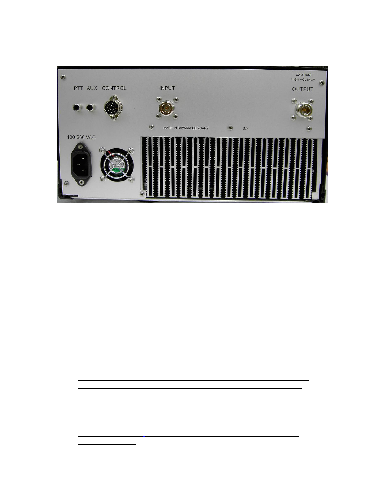
The RX/TX-switching is activated by applying zero volts or ground to the
“PTT” or pin 6 of the “CONTROL”-jack on the rear panel. This will be
indicated by the illuminated green “PTT”-LED. On most transceivers, a ground
on transmit will be supplied separately by an accessory output on their rear
panel.
Both of the two internal coaxial relays are controlled with different time delays
to allow for their specific switching times and to achieve zero power switching.
The PTT line is also used to generate the bias voltage to run the MOSFETs in
class AB. Without RF input the total idle current is 2,5 A, equivalent to
dissipating 125 watts. An internal generated and delayed PTT- function is
available at the inner contact of the rear sided “AUX“- jack to reliably control a
connected transceiver. Any potential at the inner conductor is switched to
ground.
In essence, your amplifier provides a built-in multi-level sequencer which
provides an alternate means to key your radio last.
When the amplifier PTT is activated usually via a foot switch, the preamp
voltage is dropped first, internal relays are switched, the RF amplifier section is
turned on and finally via the AUX jack a ground on transmit is available to key
your radio.
When using SSB you should not exceed 25 watts of input power to achieve best
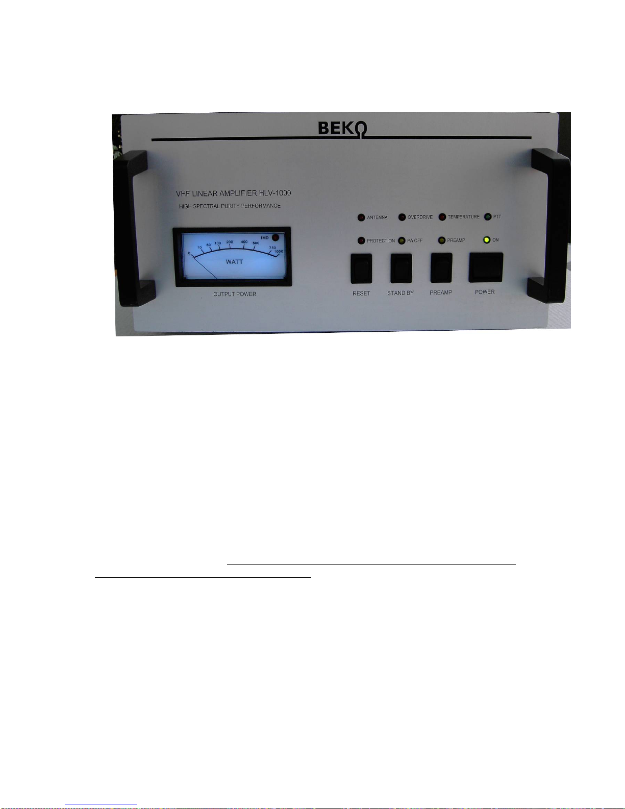
spectral purity with low inter-modulation distortion. A red LED indicator
integrated in the front panel power meter indicates the 1 dB compression point
limit at 1030 watts. Exceeding this limit will cause harmonic distortions to be
transmitted. An integrated peak-hold function provides a more effective
indication of the output power.

11
9. REMOTE control
This amplifier can also be remote controlled. RESET- , PREAMP- and PTT-
function can easily be activated by an external switch wired to ground. Output
power can be monitored. 100% of output power is equal to 10V DC on Pin 5.
Use the 7-pin DIN plug
that was delivered with your amplifier and connect the
other end to a suitable connector to your transceiver or other switching unit.

12
10. Cooling technique
The integrated axial blowers are temperature controlled and provide sufficient
cooling during long time operation at full output power with minimum noise
level. During the TX period the airflow through the RF box is increased by
higher speed of the cavity blower which is noticeable by a slight noise increase.
Especially during long term operation with MS or WSJT this is essential for
avoiding rapid temperature rise of balun and output filter coils.
To achieve best airflow for cooling, the air in- and outlets must not be covered.
Do not operate the amplifier in close proximity to heaters and radiators. If
thermal shut down occurs you should wait until the device temperature
decreases sufficiently before switching on the amplifier again. Please read also
our “Safety instructions” and “Electrical connections”.
ATTENTION !
This device is not designed for 100% duty cycle at rated output power.
Only an intermediate operation including a sufficient recovering time for
cooling is permitted. Max. duration for a once non stop TX-period @30°C
or 86°F is 5 minutes.

13
11. Block diagram

14
12. Adjustment of protection thresholds
In some cases the default adjustments are too sensitive and need some slight correction. In the
picture below all trimpots incl. their functions are shown. Turning the slots clockwise is equal
to + or upward direction and verse vice. Readjustment should be done very carefully
otherwise the effect of protection is cancelled.
Table of contents
Other Beko Amplifier manuals