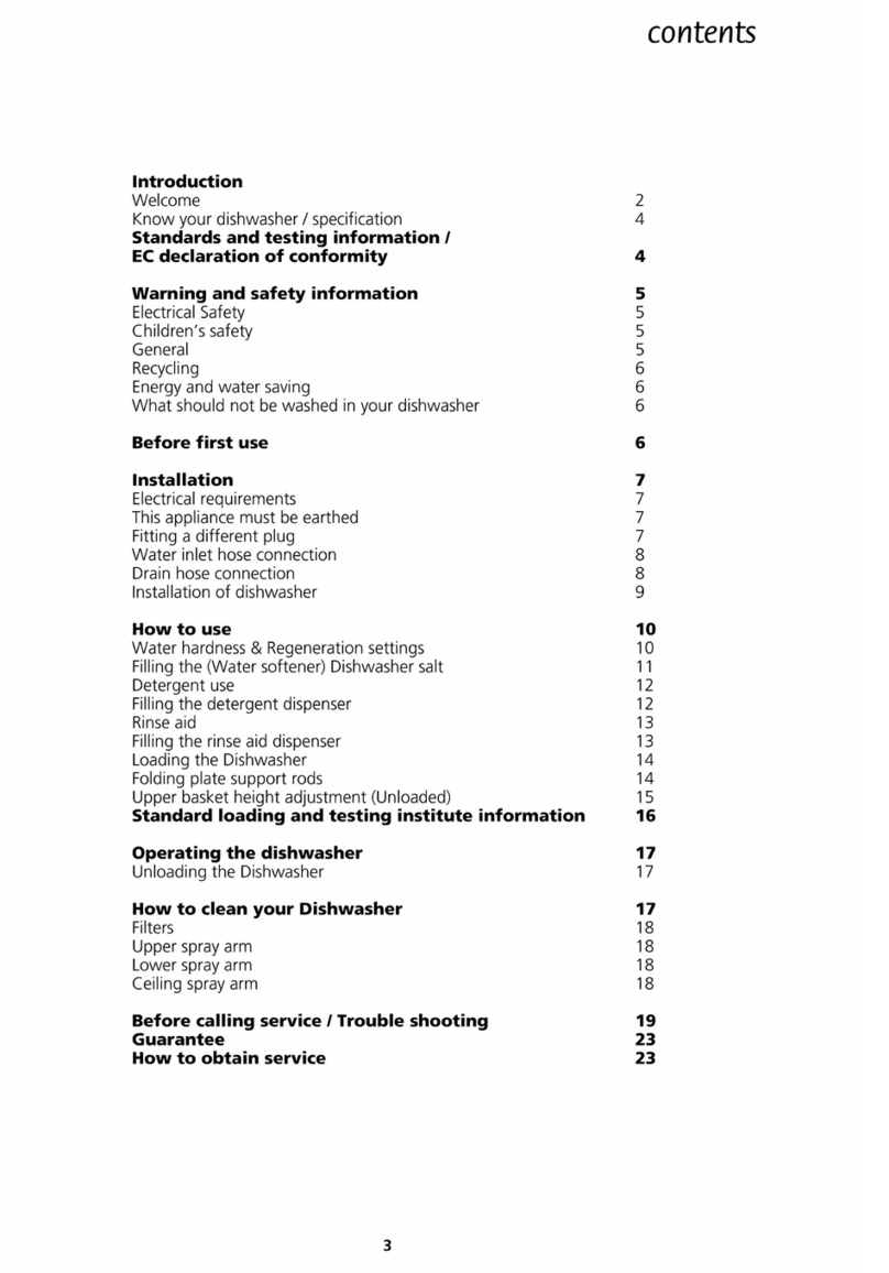
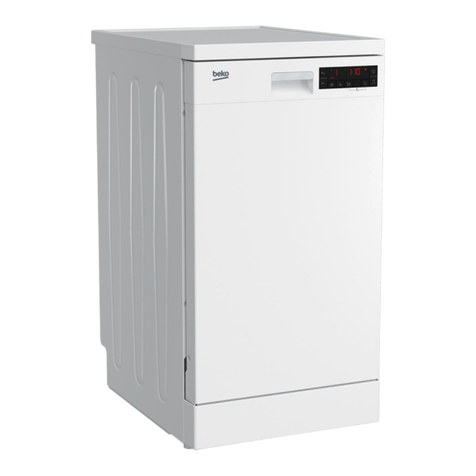
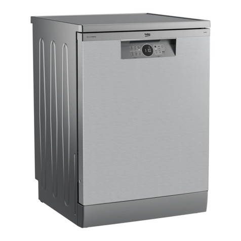
Beko DFN2520S Quick start guide

1799841888
6210
3320
3322
3321
3510
3511
3513
5051
5052
5050
3310
3010
6211
5061
5062
5060
Main Body
Main Body
Gövde Grubu
Gövde Grubu
R
R
Date/T
Date/T
ari
ari
Rev No
Rev No

9022
20 9981 1889
RDate/Tarih Rev No
r
h
a
h
r
z
d c
7160
7835
9016
a
e
7839
9016
7215
5830
6315
5831
dc
e
7140
7102
7103
7100
6160
0220 L
0221 R
0610
2610
2611
2612
z
7842
0654
0655
9115
9115
9118
1310
7162
1201
9113
9213
0470
0471
0440
0473 R
0472 L
2000
9640
1910
9113
7560
0040
0110
9115
7169
9014
7550
9018
4001
4002
4003
4004
4504
4200
7831
9012
9012
9015
9013
4500
t
6311
9154
4000
9155
0013
4901
0240
9115
7834
4210
7810
9930
9101
9016
5710
9115
7013
7010
0011 L
0012 R
9113
0650
0300
7561
7169
7842
7011
4300
6920
7910
7510
7161
0653
1912
1911
9641
s
t

4800
0403
1920
9113
9153
0401
0402
1200
9114
9105
17 9983 1889
6800
6811
6802
6801
Kapi grubu
Door group
0656
0652
6330
1300
9115
0500
0530
1030
6161
0657
0659
0658
1230

17 9982 1720
RDate/Tarih
7630
7620
7640
7610
2430
2433
9935
2424
2423
2420
2421
Su sistemi
Inner tub
2413
2414
7220
7211
7611
9102
7260
7264 7262
7266
726172637265
7221
2411
2425
2426
2427

DFN2520S
REPERE REFERENCE DESIGNATION
Q
11 1881810100 SUPPORT PIED GAUCHE 1
12 1881810200 SUPPORT PIED DROIT 1
13 1881790100 SUPPORT DE PIED 2
40 1880080392 SOCLE 1
110 1883140100 PIED AJUSTABLE 4
220 1880111310 PANNEAU GAUCHE 1
221 1880111410 PANNEAU DROIT 1
240 1880012000 SUPPORT CONTREPOIDS 1
300 1742201300 DESSUS 1
401 1880290200 CHARNIERE DROITE 1
402 1880290100 CHARNIERE GAUCHE 1
403 1880040100 SUPPORT CHARNIERE 1
440 1881020100 RESSORT DE PORTE 2
470 1881040200 POULIE DE PORTE 2
472 1881090100 FIXATION PLASTIQUE DE RESSORT 1
473 1881090200 FIXATION PLASTIQUE DE RESSORT 1
500 1742031000 PLINTHE 1
530 1880250600 SUPPORT DE PLINTHE 1
610 1880590100 CONTREPOIDS 1
650 1882430400 ISOLATION DE CUVE 1
652 1740290100 ISOLANT ARRIERE 1
653 1884750100 ISOLATION DESSUS DE CUVE AVANT 1
654 1884740100 ISOLATION ARRIERE 2
655 1886840100 ISOLATION DE CUVE GAUCHE 1
656 1882420100 ISOLATION DE PLINTHE 1
658 1886820300 ISOLATION DE PANNEAU DE FACADE 1
1030 1742010610 PANNEAU DE PORTE 1
1200 1732600100 CONTRE PORTE AVEC ISOLEMENT 1
1201 1880020100 SUPPORT BANDEAU AVANT 1
1230 1882410100 ISOLATION DE PORTE 1
1230 1886810100 ISOLATION DE PORTE 1
1300 1880300100 ENSEMBLE DE SECURITE DE PORTE 1
1310 1881970100 CROCHET DE VEROUILLAGE 1
1910 1884690100 JOINT DE TOUR DE PORTE 1
1911 1882250100 PIED JOINT DROIT 1
1912 1882250200 PIED JOINT GAUCHE 1
1920 1882470100 JOINT BAS DE PORTE 1
2000 1740002000 CUVE 1
2411 1883600300 TABLETTE 4
2413 1885800200 ROULETTE SUPERIEUR 8
2414 1733400200 PANIER SUPERIEUR + ROULETTES 1
2420 1733301800 PANIER INFERIEUR + ROULETTES 1
2421 1885900400 ROULETTE INFERIEUR 8
2423 1733320300 PETIT SUPPORT ASSIETTES GAUCHE 2
2424 1733330300 PETIT SUPPORT ASSIETTES DROIT 2
2425 1733360200 CROCHET GAUCHE BLEU 2
2426 1733370200 CROCHET DROIT BLEU 2
2428 1881560400 DECO PANIER 1
2429 1881590400 DECO PANIER 1
2430 1883200100 PANIER A COUVERTS 1

2433 1881860100 GRILLE DE PANIER A COUVERTS 1
2610 1880240100 RAIL DE PANIER 2
2611 1880580100 EMBOUT DE RAIL ARRIERE 2
2612 1880570100 EMBOUT DE RAIL AVANT 2
3010 1746011886 BANDEAU 1
3310 1742181000 MANETTE PROGRAMMATEUR 1
3320 1742041000 BOUTON M / A 1
3321 1742191000 BOUTON DEPART 1
3510 1742170100 INTERCALAIRE 1
3511 1742160100 DIFFUSEUR LUMINEUX 2
3513 1742320100 DIFFUSEUR LUMINEUX 1
4000 1740700200 POMPE CYCLAGE 1
4001 1880390100 FIXATION MOTEUR 1
4002 1740150100 FIXATION DE POMPE 1
4003 1881440100 SUPPORT MOTEUR PLASTIQUE 1
4004 1740600100 ENSEMBLE FIXATION MOTEUR 1
4200 1883790200 CONDENSATEUR 1
4210 1883880100 FILTRE ANTI PARASITE 1
4300 1740300100 POMPE DE VIDANGE 1
4500 1888130100 RESISTANCE 1
4504 1719990100 DURITE RESISTANCE / POMPE 1
4800 1735870100 CABLAGE 1
4901 1892101600 CORDON D'ALIMENTATION 1
5050 1899450250 MODULE 1
5052 1746380300 COUVERCLE ARRIERE DE MODULE 1
5060 1880601305 PLATINE DE DEPART DIFFERE 1
5061 1746310300 DIFFUSEUR DE LUMIERE 1
5710 1883570100 ELECTROVANNE 1
5830 1729900200 DEBIMETRE 1
6160 1809700000 CONTACTEUR DETECTEUR DE SEL 1
6161 1718830100 CONTACT NIVEAU DE RINCAGE 1
6210 1883250100 INTERRUPTEUR M / A 1
6211 1734600100 SELECTEUR DE FONCTION 1
6311 1883240100 CONTACT ANTIDEBORDEMENT 1
6315 1729930101 DEBIMETRE 1
6330 1831830001 INTERRUPTEUR DE PORTE 1
6800 1718600200 BOITE A PRODUIT 1
6801 1718670100 JOINT DE BOITE A PRODUIT 1
6802 1831470000 ELECTRO-AIMANT 1
6811 1718750100 BOUCHON DETERGENT 1
6920 1887740101 SONDE 1
7010 1805100200 TUYAU D'ARRIVEE D'EAU 1
7011 1883740100 SUPPORT TUYAU DE VIDANGE 2
7013 1800710000 FILTRE ARRIVEE D'EAU 1
7100 1744000300 POT A SEL 1
7102 1883970100 ECROU DE BOITE A SEL 1
7103 1800720600 JOINT DE BOITE A SEL 1
7104 1744250100 JOINT TORIQUE 2
7140 1883900100 BOUCHON + JOINT DE BOITE A SEL 1
7160 1741600200 REPARTITEUR 1
7161 1882630100 JOINT DE REPARTITEUR 1
7162 1882620500 ECROU DE LA GRILLE DU REPARTITEUR 1
7169 1800862100 DURITE 1
7211 1746100100 BRAS DE LAVAGE INFERIEUR 1
7215 2002372100 COLLIER DE VIDANGE 1
7220 1746200100 BRAS DE LAVAGE SUPERIEUR 1
7221 1880900300 ENSEMBLE SUPPORT BRAS SUPERIEUR 1
7260 1881240100 CONDUIT INTERIEUR DU BRAS 1
7261 1737910100 GUIDE SUPPORT DE BRAS 1
7262 1733430100 LOGEMENT DE SUPPORT DE BRAS SUPERIEUR 1
7263 1881280100 JOINT ISOLATION 1
7264 1881360100 FIXATION DE SUPPORT DE BRAS 1
7265 1881370100 CLAPET DE BRAS SUPERIEUR 1
7266 1740270100 SUPPORT DE BRAS DE LAVAGE 1
7510 1741501800 BOL DE FOND DE CUVE 1
7550 1740110100 DURITE COUDEE 1
7560 1888100100 KIT LOGEMENT CONTACT ANTI DEBORDEMENT 1
7561 1884280100 FLOTTEUR ANTI DEBORDEMENT 2
7610 1740400100 TAMIS 1
7611 1740900200 SUPPORT DE BRAS INFERIEUR 1
7620 1740220100 FILTRE FOND DE CUVE 1
7630 1740230100 FIXATION DE FILTRE 1
7640 1740800100 ENSEMBLE DE FILTRE 1
7810 1740160300 TUYAU DE VIDANGE 1
7831 1740130100 DURITE POMPE / RESISTANCE 1
7834 1800631600 DURITE REPARTITEUR / ELECTROVANNE 1
7835 1800632000 DURITE REPARTITEUR / DEBIMETRE 1
7839 1800864100 DURITE REPARTITEUR / POT A SEL 1
7842 1800862300 DURITE 1
7910 1740050100 JOINT BOL 1
8004 1719510100 CONDUIT D'ASPIRATION 1
8005 1719490100 JOINT DE CONDUIT D'ASPIRATION 1
8006 1719590100 GRILLE 1
9012 2002372200 COLLIER DE DURITE 1
9014 2002372500 COLLIER DE DURITE COUDEE 2
9015 2002373200 COLLIER DE DURITE 1
9016 2002370800 COLLIER DURITE REPARTITEUR / ELECTROVANNE 4
9018 1889280600 COLLIER DE DURITE 2
9022 1883170100 SUPPORT DE CORDON 1
9026 2002370900 COLLIER DE DURITE 2
9101 1831680000 VIS 1
9102 1889340100 VIS 5
9104 1803430200 VIS 5
9105 1883430100 VIS 6
9113 1883470100 VIS 28
9114 1883460100 VIS 6
9115 1801080100 VIS SUPPORT CONTREPOIDS 18
9116 1889330100 VIS 2
9118 1883410100 VIS 4
9153 1802860200 ECROU 4
9154 1882290200 VIS CAPOT 4
9155 1883440100 VIS 1
9213 1831780000 CLIP DE POULIE DE PORTE 2
9640 1882280200 ISOLANT 1
9641 1880270200 ISOLATION 2
9930 2002740000 COL DE CYGNE 1

9935 1850330000 ENTONNOIR A SEL 1
Softening Adjustment:
In order to enter the softening adjusting mode, select the knob position of 1 while the DW is out of energy
(on/off is shut) then press the start button and energize the DW and keep pressing on the button for 5
seconds, after this DW enters the softening adjusting mode. The adjusted softening level shown by the
program follow up indicators for 5 seconds after entering the mode. Softening level should be decreased
or increased by turning the knob to the positions of 2, 3, 4, 5:
For the 1st level select position 1 (regenerates for every 255 lt water inlet) (Washing indicator is on).
For the 2nd level select position 2 (regenerates for every 105 lt water inlet) (End indicator is on).
For the 3rd level select position 3 (regenerates for every 45 lt water inlet) (Both indicators on).
For the 4th level select position 4 (regenerates for every 30 lt water inlet) (Program following
indicators are off).
For the 5th level select position 5 (regenerates for every 12 lt water inlet) (Program following
indicators blink).
After selecting the required level of softening, save the selected level to the memory by pressing the start
button and exit the level adjusting mode by shutting down the machine. After the last draining process of
the last hot rinsing step, regeneration valve is energized automatically by the control system if there exits
a need for a regeneration process. 10 minutes waiting period is required as the next step of the
regeneration process. This period is followed by 2,8lt water take-in to remove the salty water from the
regeneration unit.
Functional Test:
In order to enter the functional test mode (short program mode), select the knob position of 2 while the
DW is out of energy (on/off is shut) then press the start button and energize the DW and keep pressing on
the button for 5 seconds. All of the indicators turns on for 2 seconds after entering the short program
mode. Program following indicators blink if there exist any fault within the memory of the control system.
After entering the short program mode, start the short program by pressing the “start” button. Short
program follows the steps below:
1. Draining (and Fan - if exists on the machine - ) starts (30 seconds)
2. Water inlet (4.0 lt)
3. Water circulation, heating, detergent (60 seconds)
4. Water circulation, heating (120 seconds)
5. Draining (30 seconds)
6. Regeneration (60 seconds)
7. Water inlet, draining (for cleaning the resin) (3.0 lt)
8. Draining (30 seconds)
During the short program, the program following indicators is used to inform the service stuff in the case of
any fault detection:
All program following indicators are off No fault detected
Washing indicator is on Water inlet or water counter is faulty
End indicator is on NTC is faulty
EEPROM Reset:
In order to enter the EEPROM Reset mode, select the knob position of 5 while the DW is out of energy
(on/off is shut) then press the start button and energize the DW and keep pressing on the button for 5
seconds, after this control card automatically resets the content of EEPROM and End indicator starts
blinking. In order to continue with the normal operation, DW should be shut-down from the on-off switch
and then re-energized.

Machine is not
runnig
Is start/stop
indicator on?
Check supply,
supply cord and
cable connections
of the start/stop
swicth
Select the
functional test
mode, and start
the functional test
Does the drain
pump work?
No
Yes
Check the door
switch and the
connections
No
Yes
Check overflow
gauge
TROUBLESHOOTING GUIDE FOR A3 TYPE DW’S

No water inlet to
the machine
-Check the water supply
-Check the water inlet hose (twisted or not)
-Check the sieves on the water inlet valve and the
water inlet hose
Does the drain pump work or
not at the water inlet stage
Check the
overflow gauge
and the cable
connections
Yes
Water inlet valve
energized?
No
Yes
No
Check the main
board and
connections
Check the water
inlet valve
TROUBLESHOOTING GUIDE FOR A3 TYPE DW’S

Machine takes
less water
Check the water
inlet pressure
(> 0,3 bar)
Is water inlet valve
energized at the water inlet
stage
Check the
overflow gauge
and connections
No
Yes
Check the water
inlet valve
Check the main
board and the
connections
TROUBLESHOOTING GUIDE FOR A3 TYPE DW’S
Check the
flowmeter

Machine takes
much water and
overflows
Select the funcitonal test mode.
Start the functional test. Does the
drain pump work?
No
Yes
Check the drain
hose
Check the drain
pump and the
connections
Check the water
inlet valve
Check the over
flow gauge, over
flow switch and the
connections
TROUBLESHOOTING GUIDE FOR A3 TYPE DW’S

Machine indicates
water inlet fault at
the end of the
functional test
Any fault on the
connection of the
flowmeter?
No
Yes
Fix the
connections
Is the wiring of the
water inlet valve
correct?
No
Yes
Check the
connections,
search for any
broken cable
Check the main
board and the
connections
TROUBLESHOOTING GUIDE FOR A3 TYPE DW’S

TROUBLESHOOTING GUIDE FOR A3 TYPE DW’S
Machine indicates
NTC or heater
fault at the end of
the functional test
Any problems with the
connections of the NTC
Yes Establish proper
connection
between main
board and NTC
Check whether the
NTC works
properly
No
Any fault with the
connections of the
heater
No
Yes
Check the main
board and
connections
Establish proper
connection
between main
board and heater
Check whether
there exists any
broken wiring
Check the heater
connections and
operation

L
N
PE
N
L
5
1
11
66
KN1/ 6
1
2
4
KN1/ 3
KN1/ 5
KN1/ 4
KN1/ 1
KN1/ 7
KN1/ 2
KN2/ 8
KN2/ 9
KN2/ 6
KN2/ 5
KN4/ 1
KN2/ 4
KN2/ 3
KN5/ 1
66
66
66
66
77
77
77
77
44
44
44
99 99
3333
55 55
99 99
6666
88 88 8888
44 44
11
777777
77 77
77 77
44
11 11
2
PE
5454
6
KN2/ 1
00
77
77
L
N
TB
THS
TF
HFT
WVSPM
TL
MC
RV
DD
DR
NTC
DPM
MS
MS
15
62
R
R2
DS
R
R1
IF
TUB
C
FM
KN2/ 2
C
PCB
CO
1
24
PSS
00
54 54
KN5/ 2 77 77
Door Switch
Salt Reed Relay
Thermo-fuse of Heater
Flow Through Heater
Security Thermostat
Rinse-aid Reed Relay
Terminal Block
Main Switch
Over Flow Micro Switch
Water Inlet Valve
Drain Pump Motor
MS
DS
R1
TF
HFT
THS
R2
TB
WV
CO
DPM
SPM
TL
C
RV
DD/DR
FM
NTC
PSS
Circulation Pump
Thermic of Circulation Motor
Capacitor
Regeneration Valve
Thermoactuator Dispenser Unit
Flow meter
NTC
Programme Select Switch
Colour Code
0
1
6
5
4
2
3
8
9
7
Black
Brown
Blue
Green
Yellow
Red
Orange
Grey
White
Violet
PPink
02 01 Tip Malzeme Renk Standart Ölçü
Malzeme / Material
Resim ism i / Draw ing name
Tarih İsim
04.08.2005 A. GÜR
04.08.2005 E. Çetinkaya
Tölerans ıKontrol Ma.SınıfıKomp.S.No Tip St.Değ.Ölçek
Verilmeyen Ölçüleri Ölçeksiz
Ölçüler Say.No
± 10 mm 1/1
Tip D S.No D.T.No Tarih Kontrol Onay .............. Yerine Geçti Tamamı
Wiring Diagram
2017 3587 05
ART 4
KN2/ 7
KN9/ 1
KN9/ 2
KN9/ 3
KN9/ 4
KN9/ 5
FAN FAN

WHITE 0.35
YELLOW 0.35
YELLOW 0.35
VIOLET 0.35
VIOLET 0.35
BLUE 0.35
BLUE 0.35
0.50 YELLOW
0.50 GREEN
0.50 ORANGE
0.50 VIOLET
0.50 BROWN
0.50 BLACK
0.50 BLUE
GREY 0.50
0.50 WHITE
91
DRAIN
KN2
Main Board
KN3
( Lamp side )
KN1
17
HEATER
HEATER
KN5
VIOLET 1.50
VIOLET 1.50
VIOLET 0.50
NTC
GND
GND
RINSE
SALT
GND
CNT
KN4
KN7
KN8
Programme
Select Switch
CIRCULATION
OVER FLOW SWITCH
REGENERATION
WATER INLET
DETERGENT/RINSE
NEUTRAL
NEUTRAL
LINE
Malzeme / Material
Resim ism i / Draw ing name
Tarih İsim
04.08.2005 F. Tan
04.08.2005 E. Çetinkaya
TöleransıKontrol Ma.SınıfıKomp.S.No Tip St.Değ.Ölçek
Verilmeyen Ölçüleri Ölçeksiz
Ölçüler Say.No
± 10 mm 1/1
Tip D S.No D.T.No Tarih Kontrol Onay .............. Yerine Geçti Tamamı
PCB Diagram
3017 3587 05
ART 4
FAN
KN9
15

MS
5
6
1
2
MS
DS
R1
TF
HFT
THS
R2
TB
Door Switch
Salt Reed Relay
Thermo-fuse of Heater
Flow Through Heater
Security Thermostat
Rinse-aid Reed Relay
Terminal Block
Main Switch
WV
SPM
TL
C
RV
DD/DR
FM
NTC
CO
Circulation Pump
Thermic of Circulation Motor
Capacitor
Regeneration Valve
Thermoactuator Dispenser Unit
Flow meter
NTC
Over Flow Micro Switch
Water Inlet Valve
DPM Drain Pump Motor
PSS Programme Select Switch
DS
NTC
DDDR
THS
HFT
TF
L
Main Board
1 2 3 8
N
M
S
DPM
WV
RV
4 159 6 21
KN 2
3 6
KN 1
KN 5
1
24
CO
M
TL
SPM
C
1
R
R1
C
FM
374 225
PSS
R
R2
N L
TB
IF
KN 7
1
321 KN 8
KN 6
02 01 Tip Malzeme Renk Standart Ölçü
Malzeme / Material
Resim ismi / Drawing name
Tarih İsim
04.08.2005 A. GÜR
04.08.2005 E.Çetinkaya
TöleransıKontrol Ma.SınıfıKomp.S.No Tip St.Değ.Ölçek
Verilmeyen Ölçüleri Ölçeksiz
Ölçüler Say.No
± 10 mm 1/1
Tip D S.No D.T.No Tarih Kontrol Onay .............. Yerine Geçti Tamamı
Circuit Diagram
1017 3587 05
ART 4
7
FAN Fan motor
Table of contents
Other Beko Dishwasher manuals

Beko
Beko DFN05X10W User manual

Beko
Beko DWD4310 User manual

Beko
Beko BDSN15N20X User manual

Beko
Beko DIS16010 User manual

Beko
Beko DUN28520X User manual

Beko
Beko DFN05320B User manual

Beko
Beko DFS05020W User manual

Beko
Beko DSN Series User manual

Beko
Beko 8690842204784 User manual

Beko
Beko DIS25010 User manual

Beko
Beko DIS26010 User manual

Beko
Beko DFN 6831 User manual

Beko
Beko BMA 6102 I User manual

Beko
Beko BDI1410 User manual

Beko
Beko DFN26320X2MM User manual

Beko
Beko DIS15011 User manual

Beko
Beko BMA 6302 FI User manual

Beko
Beko DFS28120X User manual

Beko
Beko DFN05R10W User manual

Beko
Beko DTC36810W User manual