Beko ARI 7757186301 User manual

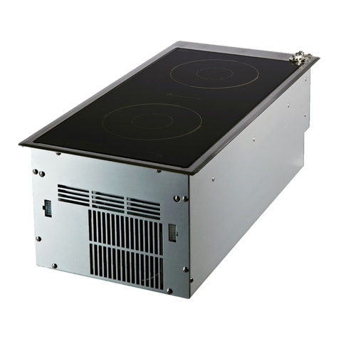
ARI Enductıon Hob
ARI BUILT IN INDUCTION HOB
SERVICE MANUAL
Servıce Manual

TR | 2
INDEX
1.BOOK COVER..………………………………………………………………………………...1
2.INDEX………..………………………..…………………………………………………………2
3. SERVICE WARNINGS........................................................................................................ 5
3.1. Symbols and Explanations ......................................................................................... 5
4. TECHNICAL SPECIFATIONS ............................................................................................... 6
5. PRODUCT ASSEMBLY / ASSEMBLY RULES / SETTINGS.......................................................... 8
5.1. Before Installation .................................................................................................... 8
5.2Installation ................................................................................................................ 8
5.3. Electric Connection................................................................................................... 9
5.4 Connection of the Electric Cable ................................................................................. 9
5.5. Mounting the Product to Place .................................................................................11
6.1. Last Check ..............................................................................................................13
6.2. Tips About Glass Ceramic Hobs .................................................................................13
6.3. Saucepan Selection..................................................................................................14
6.4. Safe Use .................................................................................................................14
6.5. Control Panel ..........................................................................................................14
6.5.1. Specifications....................................................................................................15
6.5.2. Turning on the hob............................................................................................15
6.5.3. Turning off the hob ...........................................................................................15
6.5.4. Residual heat indicator ......................................................................................15
6.5.5. Turning on the cooking zones .............................................................................16
6.5.6.Setting the temperature level..............................................................................16
6.5.7.Turning off the cooking zones:.............................................................................16
6.5.8. High Power (Booster).........................................................................................16
6.5.9. Turning off High Power (Booster) : ......................................................................17
6.5.10. Keylock ..........................................................................................................17
6.5.11. Deactivating the keylock ..................................................................................18
6.5.12. Childlock ........................................................................................................18
6.5.13. Activating the childlock ....................................................................................18
6.5.14. Deactivating the childlock.................................................................................18
6.5.15. Timer function ................................................................................................18
6.5.16. Activating the timer.........................................................................................19
6.5.16. Deactivating the timer .....................................................................................19
6.5.17. Turning off the timers earlier ............................................................................19
6.5.18.Operation time constraints................................................................................20
6.5.19. Overheating protection....................................................................................21
6.5.20. Overflow safety system....................................................................................21

TR | 3
6.5.21. Precise power setting.......................................................................................21
6.5.23. Operating noise...............................................................................................21
7. PRODUCT ACCESSORIES .................................................................................................22
7.1. Saucepan Recognition System..................................................................................22
8. INDUCTION WORKING PRINCIBLE....................................................................................23
8.1 INDUCTION CONTROL SYSTEM:..................................................................................23
8.2 How to use the hob ..................................................................................................25
8.3 Graphics of induction hob. ........................................................................................25
9. COMPONENT LIST..........................................................................................................30
9.1 Main board (Induction Generator) .............................................................................31
Function of main board...............................................................................................31
Specifications ............................................................................................................31
9.2 Filter Board:.............................................................................................................32
Function of filter board...............................................................................................32
Specifications ............................................................................................................32
9.3 Touch Control board.................................................................................................33
Function of touch control board ..................................................................................33
Specifications ............................................................................................................33
9.4 Cooling fan ..............................................................................................................33
Function of cooling fan ...............................................................................................33
Specifications ............................................................................................................33
9.5 Induction coil...........................................................................................................33
Function of induction coil ...............................................................................................34
Specifications ............................................................................................................34
10. SERVİCE FUNCTİON TEST ..............................................................................................35
10.1 Electronic control board instructions ........................................................................35
10.2 Entry Service Mode:................................................................................................37
10.3 Service Mode Control Stages ...................................................................................38
11. CONTROL PANEL.........................................................................................................42
11.1 PROPERTIES...........................................................................................................42
11.2 Cooking Zone Display..............................................................................................42
11.3 Switching on the hob ..............................................................................................42
11.4 Turning Off The Hob ...............................................................................................43
11.5 Operating cooking zones of the hob .........................................................................43
11.6 Child safety lock .....................................................................................................44
11.7 The keypad lock .....................................................................................................45
11.8 Timer function .......................................................................................................45
12. Probable failures and remedies .....................................................................................48

TR | 4
13. PROGRAM WORKFLOW................................................................................................49
14.ASSEMBLING-DISASSEMBLING EQUIPMENT / APPARATUS LIST..........................................50
15. COMPONENT ASSEMBLY / DISASSEMBLY........................................................................51
15.1 Vitroceramic plate replacement ...............................................................................51
15.2. Changing Touch Electronic Board ............................................................................52
15.3. Heater plates/ changing coils ..................................................................................55
15.4. Changing Mainboard..............................................................................................57
15.5. Changing cooling fan..............................................................................................60
15.6. Changing Filter Board.............................................................................................60
15.7. Changing plastic housing ........................................................................................61
15.8. Changing Plastic Housing Top Springs.......................................................................62
15.9. Changing mains cable.............................................................................................62
17. EXPLODED VIEW ..........................................................................................................63
18. SERVICE PART LIST .......................................................................................................63

TR | 5
3. SERVICE WARNINGS
3.1. Symbols and Explanations
Important information’s or useful hints about usage
Warning against a dangerous condition in terms of lives and
property
Warning against electric shock
Warning against fire
Warning against hot surface
Electric connection should be interrupted during the installation, maintenance, cleaning and
repair process.

TR | 6
4. TECHNICAL SPECIFATIONS
Voltage/frequency
220-240 V~/380-415 V 2N ~ 50 Hz
Total electric consumption
max. 7200 W
Fuse
min. 16 A x 2 / 32 A
Cable type/intersection
H05RR-F5 x 1,5 mm2/ 3 x 2,5 mm2
Cable length
max. 2 m
External
dimensions(height/width/depth)
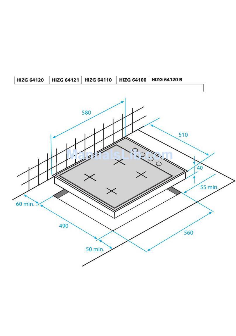
55mm/580 mm/510 mm
Mounting dimensions(height/depth)
560 mm / 490 mm
zones of hub
4 zone hob
(a)version
4 zone hob
(b)version (60
cm/70 cm)
3 zone hob
(a)version
3 zone hob
(a)version (60
cm/70 cm)
Back left
Induction hob
zone
Induction
hob zone
Back left
Induction hob
zone
Induction hob
zone
Dimension
180 mm
145 mm
Dimension
145 mm
210 mm
Power
2000 /
2300 W
1600 W
Power
1600 W
2000 / 2300 W
Front left
Induction hob
zone
Induction
hob zone
Front left
Induction hob
zone
Induction hob
zone
Dimension
180 mm
180 mm
Dimension
180 mm
145mm
Power
2000 /
2300 W
2000 W
Power
2000W
1600 / 1800 W
Front right
Induction hob
zone
Induction
hob zone
Middle
right
Induction hob
zone
Induction hob
zone
Dimension
145mm
145mm
Power
1600 /
1800 W
1600 W
Front left
Induction hob
zone
Induction
hob zone
Dimension
210 mm
180 mm
Dimension
240mm
280duo
Power
2000 / 2300
W
2000 W
Power
2000W/2300W
(Booster).
2300W/3600W
(Booster)
You can find product technical speciation’s on manusoft system.

TR | 7
declared values on the product labels or other printed documents are obtained
under laboratory conditions according to relevant standards. This values can change
according to products operational and environmental conditions.

TR | 8
5. PRODUCT ASSEMBLY / ASSEMBLY RULES / SETTINGS
5.1. Before Installation
While installing the product, obey the local electric standards
The Product is designed according to commercially available kitchen counters. There should
be a safe distance between kitchen walls and furniture. Look at the picture for appropriate
space (values in mm).
• Product is suitable for use without any support, without any cabinet, with the wall on each
side. 750 mm distance should be left on the built in hob.
• If you put a hood above the device, you should obey the advice of hoods and hood
producer.(Min 65cm)
• Remove the packing materials and shipping locks.
• Surfaces, synthetic laminates and adhesives must be resistant to heat.(minimum 100°C)
• The bench should be flat and must be fixed.
• The space on the bench which the built in hob placed on it should be cut according to
dimension of the installation guide of the hob.
5.2Installation

TR | 9
The installer should obey the local electricty standarts.
5.3. Electric Connection
Connect the product to the mains supply protected by a fuse, in accordance with the
‘’Technical Features’’ table.
• Electric cable damage can cause electric shock, short circuit or fire hazard.
• Electric cable should not be crushed, compressed or contact hot parts.
• If the electricity cable is damaged, it should be changed by an qualified electrician.
• Connection must be compatible with national procedures.
Network supply data should be the same with the type of product label.
Product type label is behind the product.
• Product’s connection cable should be appropriate with the ‘’Technical Features’’ table.
Electric shock hazard. Please disconnect the appliance from mains before installing.
5.4 Connection of the Electric Cable
1. If separating all mains supply poles is not possible, a separation unit (fuse, line safety
switch, contactor) with 3 mm contact distance should be connected with accordance to IEEE
guidelines.
Additional protection should be provided through residual current circuit breaker.
If a cable given is with the product;
2. Connect the cables for the single-phase:

TR | 10
• Brown cable=L(phase)
• Blue cable=N(neutral)
• Green/Yellow cable=E(ground)
3. Connect the cables for the two phase:
• Brown cable=L1(Phase1)
• Black cable=L2(phase2)
• Blue cable=N(neutral)
• Green/Yellow cable=(E)

TR | 11
5.5. Mounting the Product to Place
If the product is mounted on the top of a drawer, bottom side must be protected by furniture as
seen below.
1
min. 25 mm
While mounting the built in hob above a cabinet, please refer to the picture below..
If the built in hob bottom;
*
min.
At least 180 cm2 air gap is required at the back of the furniture.
*
min.
During the installation of an induction built in hob, place the product in parallel to the
mounting surface. A seal should be applied between built in hob and bench to prevent any
liquid pass.

TR | 12
1. Prepare the surface of the bench as shown in the figure.
2. The sealing gasket is given with the product, paste it between built in hob and bench as
shown in the figure.
3. Center the product in the bench.
4. While fixing the built in hob, connect the bottom of the plate mounting holes in the
housing.
5. Center the product in the bench.
6. While fixing the built in hob, connect the bottom of the plate mounting holes in the
housing.
1. Built in hob
2. Mounting clamp
3. Bench
» Back wiev (connection holes)

TR | 13
Connection of the different holes can damage gas and electric system so it is
undesirable in terms of security.
6.1. Last Check
1. Apply power to the appliance.
2. Control the functions.
6.2. Tips About Glass Ceramic Hobs
Glass ceramic surface is heatproof and is not affected by big temperature differences.
• Do not use the glass ceramic surface as a place of storage or as a cutting board.
• Use only the saucepans and pans with machined bottoms. Sharp edges create scratches on
the surface.
• Do not use aluminum vessels and saucepans. Aluminum damages the glass ceramic
surface.
Spills may damage the glass ceramic surface and cause fire
Do not use vessels with concave or convex bottoms.
Use only the saucepans and pans with flat bottoms. They ensure
easier heat transfer.
If the diameter of the saucepan is too small, energy will be wasted.

TR | 14
6.3. Saucepan Selection
For induction hobs, use only vessels suitable for induction cooking.
Saucepan test
Use following methods to test whether your saucepan is compatible with the induction hob
or not.
1. Your saucepan is compatible if its bottom holds magnet.
2. Your saucepan is compatible if "u" does not flash when you place your saucepan on
cooking zone and start the hob.
6.4. Safe Use
Do not select high heating levels when you use a non-sticking (teflon) saucepan with
no oil or with very little oil.
Do not put metal items such as forks, knives or saucepan covers onto your hob since
they can get heated.
Never use aluminum foil for cooking. Never place food items wrapped with
aluminium foil onto the cooking zone.
When the hob is running, keep items with magnetic properties such as credit cards or
cassettes away from the hob.
6.5. Control Panel

TR | 15
6.5.1. Specifications
This product is controlled with a touch control panel. Each operation done on the
touch control panel will be confirmed by an audible signal.
Always keep the control panel clean and dry. Having damp and soiled surface may
cause problems in the functions.
6.5.2. Turning on the hob
1. If Touch the "" key on the control panel."0" icon appears on all cooking zone displays.
If no operation is performed within 10 seconds, the hob will automatically return to Standby
mode.
6.5.3. Turning off the hob
1. Touch the "" key on the control panel.The hob will turn off and return to Standby mode.
"H" or "h" symbol that appears on the cooking zone display indicates that the cooking zone
is still hot. Do not touch cooking zones.
6.5.4. Residual heat indicator

TR | 16
"H" symbol that appears on the cooking zone display indicates that the hob is still hot and
may be used to keep a small amount of food warm. This symbol will soon turn to "h" which
means ‘still hot’..
When power is cut off, residual heat indicator will not light up and does not warn the user
against hot cooking zones.
6.5.5. Turning on the cooking zones
1. Touch "" key to turn on the hob.
2.Touch the selection key of the cooking zone you want to turn on.
"0" symbol appears on the cooking zone display and the related display illuminates more
brightly.
If no operation is performed within 20 seconds, the hob will automatically return to Standby
mode.
6.5.6.Setting the temperature level
Touch "" or "" keys to set the temperature level between "1" and "9" or "9" and "1".
6.5.7.Turning off the cooking zones:
A cooking zone can be turned off in 3 different ways:
1.By dropping the temperature level to "0"
You can turn the cooking zone off by dropping the temperature adjustment to "0" level.
2.By touching the relevant cooking zone symbol "" for a certain time
Turn on the cooking zone by pressing relevant symbol "" for a certain time to drop
temperature value to "0".
3.By using the turn-off on the timer option for the desired cooking zone
When the time is over, the timer will turn off the cooking zone assigned to it. "0" or "00" will
appear on related display.
When the time is over, an audible alarm will sound. Touch any key on the control panel to
silence the audible alarm.
6.5.8. High Power (Booster)

TR | 17
For rapid heating, you can use booster function “P”. However, this function is not
recommended for cooking a long time. Booster function may not be available in all cooking
zones.
Turning on High Power (Booster) :
1. Touch "" key to turn on the hob.
2. Select the desired cooking zone by touching the cooking zone selection keys.
3. Touch "" or "" key firstly to reach the level "9".
4. When the cooking zone is at level "9", touch "" key once to set cooking zone temperature
to "P".
6.5.9. Turning off High Power (Booster) :
• To disable the Booster function, touch "" and set the temperature to level "9".
Cooking zone goes out of booster and continues to operate at level "9".
• You can decrease the temperature level by touching "" or you can switch off the cooking
zone completely by decreasing the temperature level to "0".
6.5.10. Keylock
You can activate the keylock to avoid changing the functions by mistake when the hob is
operating.
Activating the keylock
1. Touch "" key to turn on the hob.
2. Touch "" and "" keys simultaneously to activate the keylock

TR | 18
Keylock will be activated and the dot on the symbol "" will light up. If you turn the hob off
when the keys are locked, the keylock will be activated next time you turn the hob on again.
Key lock must be deactivated in order to be able to operate the hob.
6.5.11. Deactivating the keylock
1. When the keylock is active, touch "" and "" keys simultaneously.
Keylock will be de activated and the dot on the symbol "" will disappear.
6.5.12. Childlock
You can protect the hob against being operated unintentionally in order to prevent children
from turning on the cooking zone. Child Lock can only be activated and deactivated in
Standby mode.
6.5.13. Activating the childlock
1. Touch "" key to turn on the hob.
2. Touch "" and "" keys simultaneously After “beep” signal touch "" to activate the childlock.
Childlock will be activated and "L" symbol appears on all cooking zone display.
6.5.14. Deactivating the childlock
1. When the keylock is active, touch "" key to turn on the hob.
2. Touch "" and "" keys simultaneously After “beep” signal touch "" to deactivate the
childlock.
Childlock will be deactivated and "L" symbol disappears on all cooking zone display.
6.5.15. Timer function
This function facilitates cooking for you. It will not be necessary to attend the oven for the
whole cooking period. Cooking zone will be turned off automatically at the end of the time
you have selected.

TR | 19
6.5.16. Activating the timer
1. Touch "" key to turn on the hob.
2. Select the desired cooking zone by touching the cooking zone selection keys.
3. Touch "" or "" keys to set the desired temperature level.
4. Touch "" key to turn the timer on.
"00" symbol will appear on timer display and decimal point will appear on the selected
cooking zone display.
Right rear and left rear cooking zone displays serve as timer display when the timer is active.
5. Touch "" or "" keys to set the desired time
The timer can only be set for the cooking zones already in use.
Repeat the above procedures for the other cooking zones for which you wish to set the
timer.
Timer cannot be adjusted unless the cooking zone and the temperature value for the
cooking zone are selected.
When the cooking zone for which a timer was set is selected, you can see the remaining time
by touching the "" key again.
6.5.16. Deactivating the timer
Once the set time is over, the hob will automatically turn off and give an audible warning.
Press any key to silence the audio warning.
6.5.17. Turning off the timers earlier

TR | 20
If you turn off the timer earlier, the hob will carry on operating at the set temperature until
it is turned off.
1. Select the cooking zone you want to turn off.
2. Touch "" key to turn the timer on.
3. Until "00" appears on the timer screen, touch "" to set the value to "00".
Dot shaped light on the relevant cooking zone display itself turns off completely after having
flashed for a certain period of time and the timer is cancelled.
Using induction cooking zones safely and efficiently
Operating principles: Induction hob heats directly the cooking vessel as a feature of its
operating principles. Therefore, it has various advantages when compared to other hob
types. It operates more efficiently and the hob surface does not heat up.
Induction hob is equipped with superior safety systems that will provide you maximum
usage safety.
Your hob can be equipped with induction cooking zones with a diameter of 145, 180, 210
mm depending on the model. With induction feature, each cooking zone detects each vessel
placed on them. Energy builds up only where the vessel contacts with the cooking zone and
thus, minimum energy consumption is achieved,
6.5.18.Operation time constraints
The hob control is equipped with an operation time limit. When one or more cooking zones
are left on, the cooking zone will automatically be deactivated after a certain period of time
(see Table-1). If there is a timer assigned to the cooking zone, the timer display will also turn
off later.
Operation time limit depends on the selected temperature level. Maximum operation time is
applied at this temperature level.
The cooking zone may be restarted by the user after it is turned off automatically as
described above.
Table-1: Operation time limits Temperature level
Temperature
level
Operation time
limit - hour
0
0
1
6
2
6
3
5
4
5
5
4
Table of contents
Other Beko Hob manuals

Beko
Beko HIC 64102 User manual

Beko
Beko HIMW 95225 SXE User manual

Beko
Beko OSE 24130 B User manual

Beko
Beko HIMW 64225 S User manual

Beko
Beko HISG 64120 User manual

Beko
Beko HII 63500 T User manual

Beko
Beko HII 64300 T User manual

Beko
Beko HIZG 64125 SR User manual

Beko
Beko HIC 63401 T User manual

Beko
Beko HII 64400 ATX User manual

Beko
Beko HIC 64101 User manual

Beko
Beko HII 64400 AT User manual

Beko
Beko HIC 64102 User manual

Beko
Beko HII64401SMTX User manual

Beko
Beko Hll74700UF User manual

Beko
Beko HIC 64102 User manual

Beko
Beko BE61HL P User manual

Beko
Beko HIC64100 User manual

Beko
Beko HIC 64403 TX User manual

Beko
Beko HII 64500 FT User manual